
Numerical tool with mean stress correction demonstrated for fatigue life estimation of thermoplastic composites
To aid design of fatigue-resistant structures, Econ Engineering has developed an algorithm to evaluate ply-based cyclic stiffness degradation combined with an FE failure check, validated for a CF/PAEK pressure vessel.


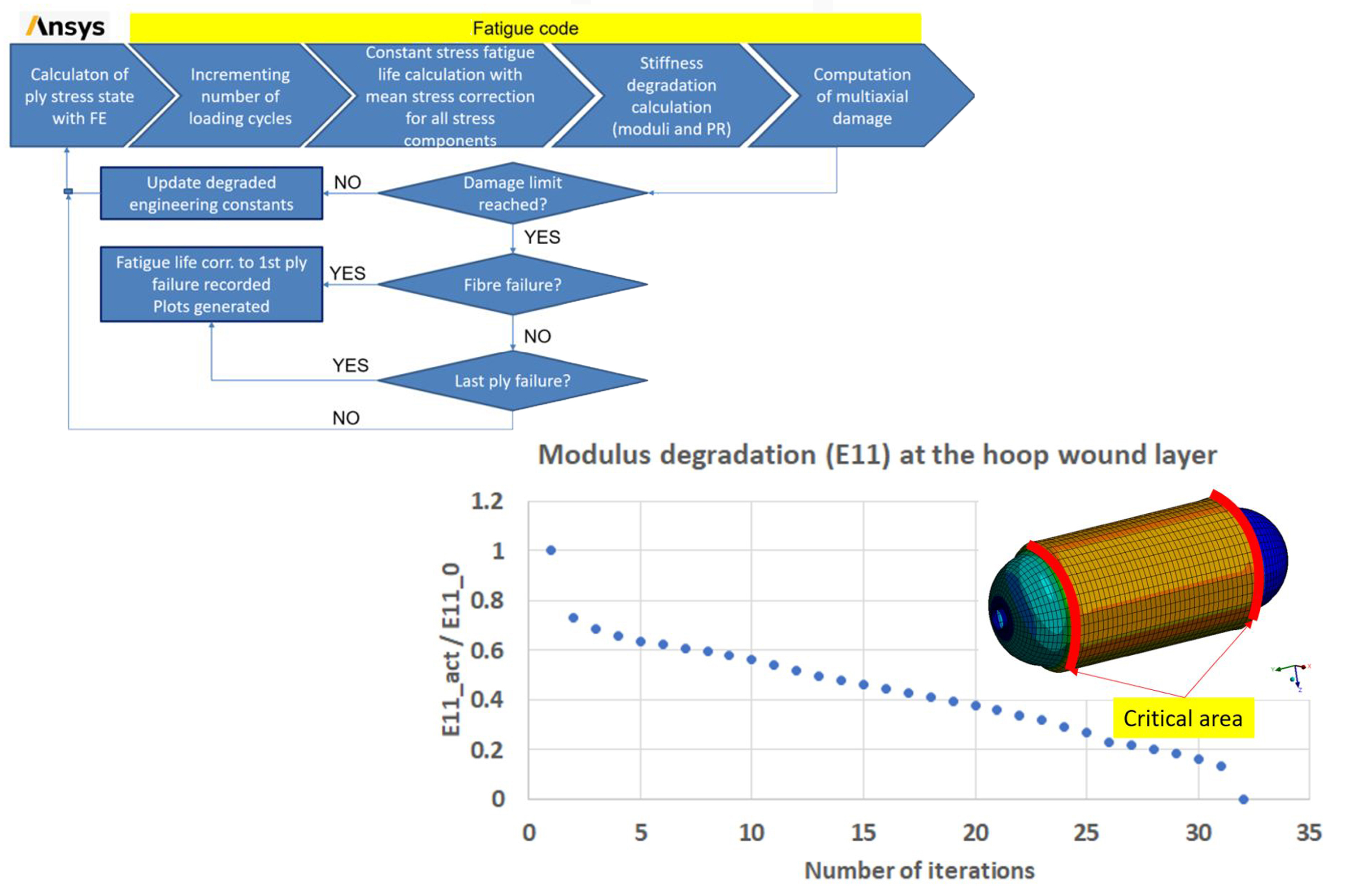
Econ Engineering has demonstrated an automated simulation workflow (top) to predict the fatigue life of thermoplastic composite structures such as a pressure vessel (bottom). Photo Credit: Econ Engineering
The replacement of well-characterized thermoset matrix composites with thermoplastic composites is being driven by the increasing need for recyclability, as well as the potential for much faster cycle times and fastener-less assemblies via welding. Although there are indeed companies producing thermoplastic composite structures that have demonstrated years of successful use, these designs have been developed using internal methods and design rules. Currently, there are no standard methodologies or commercial calculation tools to design such materials to avoid fatigue failure.
In general, thermoplastic matrix materials exhibit more susceptibility to cyclic loading failure, manifested by phenomena including steeper SN curves (plots of cycles (N) vs. stress (S) to failure), time-dependent deformation and failure behavior due to viscoelastic mechanisms (creep and/or relaxation)), as well as lower endurance limits and higher levels of ductility in matrix behavior that can lead to plasticity-driven failure modes.


Thus, the need for high-fidelity methods of predicting fatigue life for these materials is increasingly important as they are adopted for applications such as large aerospace and automotive structures and pressure vessels storing fuels such as hydrogen — structures that operate for long periods of time and require durability under cyclic loads. As a result, there is strong interest in a technique and an associated automated simulation tool to support designing fatigue-tolerant thermoplastic composite structures.
Fatigue failure example, models using progressive damage and generic approach
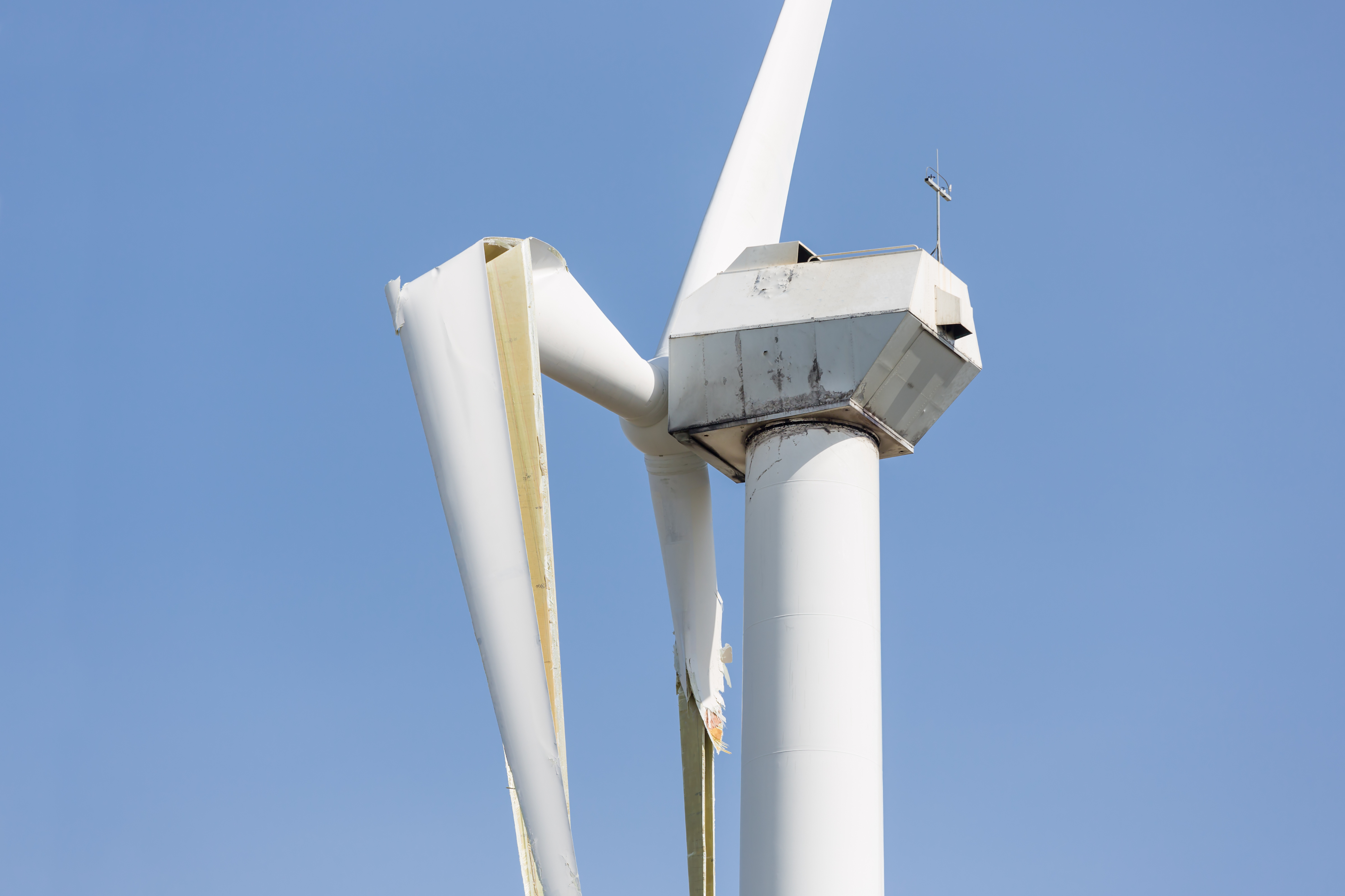
Figure 1. Premature wind turbine blade failure after a storm. Photo Credit: Econ Engineering
The importance of fatigue analysis can be seen in fiber-reinforced epoxy wind turbine blades, where it is needed to address fluctuating and randomly varying wind loads that can cause premature failure.
There are examples of fatigue life prediction for such composites using progressive damage modeling1, as well as examples within commercial analysis software such as Ansys (Canonsburg, Pa., U.S.) that have exploited automation and scripting facilities for geometry preparation, preprocessing, structural analysis, result evaluation and post-analysis fatigue assessment in one generic workflow2. However, these have not yet been extended to thermoplastic composites.
The method discussed here is actually generic in application, demonstrated with good results for both thermoset and thermoplastic composite structures. It is also specifically based on modeling of real physical phenomena, namely the cyclic degradation of stiffness and the state of damage in composite laminates made with continuous or short fiber (compared to methods developed mainly for short fiber thermoplastic composites). At the same time, it uses commercial Ansys finite element (FE) tools to get actual working stresses in the plies.
New algorithm to predict the cyclic response of fiber-reinforced composites
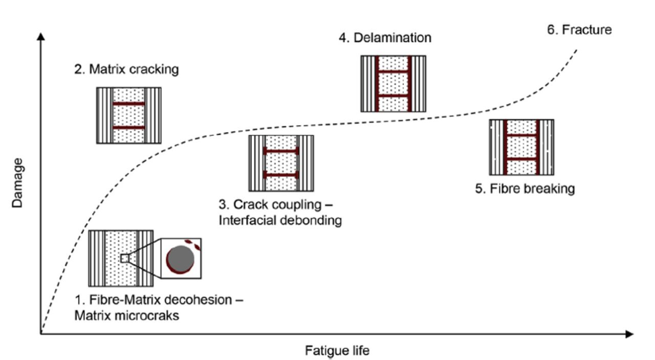
Figure 2. Degradation process of a composite ply during cyclic loading. Photo Credit: Reference 3, Caous, et al., Composites Part B Engineering
As a result of previous R&D activities, Econ Engineering (Budapest, Hungary) has developed an algorithm to predict the cyclic response of continuous fiber-reinforced polymer composites by integrating FE assessment into a stiffness degradation and cyclic failure assessment algorithm based on theories taken from literature. According to the underlying theory as described by Caous3 et al., under cyclically varying loading conditions the composite ply undergoes a sequential damage evolution process (Fig. 2).
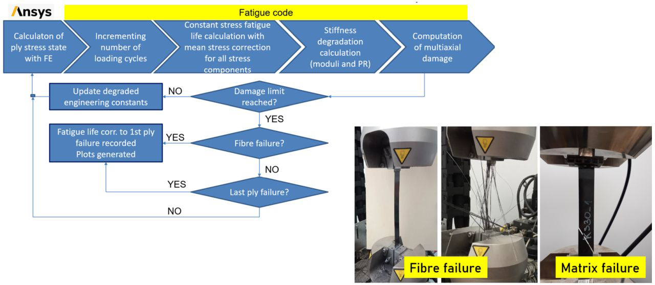
Figure 3. The automated composite fatigue assessment workflow. Photo Credit: Econ Engineering
The process corresponding to matrix microcracking and the crack density saturation up to the failure of the weakest layer is a stable and gradual process that can be well characterized by empirical laws. These microstructural changes are manifested in the global reduction of ply stiffness which can be modeled in FE assessment by changing the corresponding properties following the selected degradation rule. Previous R&D work performed by Econ Engineering has resulted in an automated system for the cyclic lifespan prediction of any composite laminate. The algorithm is detailed in Fig. 3.
Strengths and features of proposed methodology
One value-adding feature of this methodology is the simultaneous monitoring of mean stress-dependent stiffness degradation over successive cycles using empirical interaction degradation rules and orientation-dependent Haigh-diagram. The method also includes the effect of complex in-plane stress states of a ply by considering all three in-plane load directions (normal, transverse and shear) in the fatigue damage calculation. In addition, it includes a static progressive damage assessment method as per Puck4 to provide a more realistic fatigue life prediction for initially overloaded laminates. The procedure has also been coded in the form of a complex automated workflow, where the actual stress state for each ply is evaluated by appropriate FE assessment and ply-based residual stiffness analysis combined with a failure check executed in an external routine.
Econ Engineering’s numerical tool can provide reliable cyclic life prediction for any ply stacking sequences and loading conditions, combined with complex geometries, due to the fact that the failure check is based on FE analysis. The internal failure mode check can also determine if an expected ply breakage leads to catastrophic failure or if the surrounding layers can take over the load. This is to avoid calculated fatigue lives that are unrealistically short. Thus, the developed tool offers a convenient and reliable means for generating safe designs that must exhibit high cyclic strength. This tool is planned to be migrated into the Ansys Workbench environment in the form of a user-defined plug-in that may be attached to any composite component structural assessments done with layered shell elements.
Initial validation in laminates
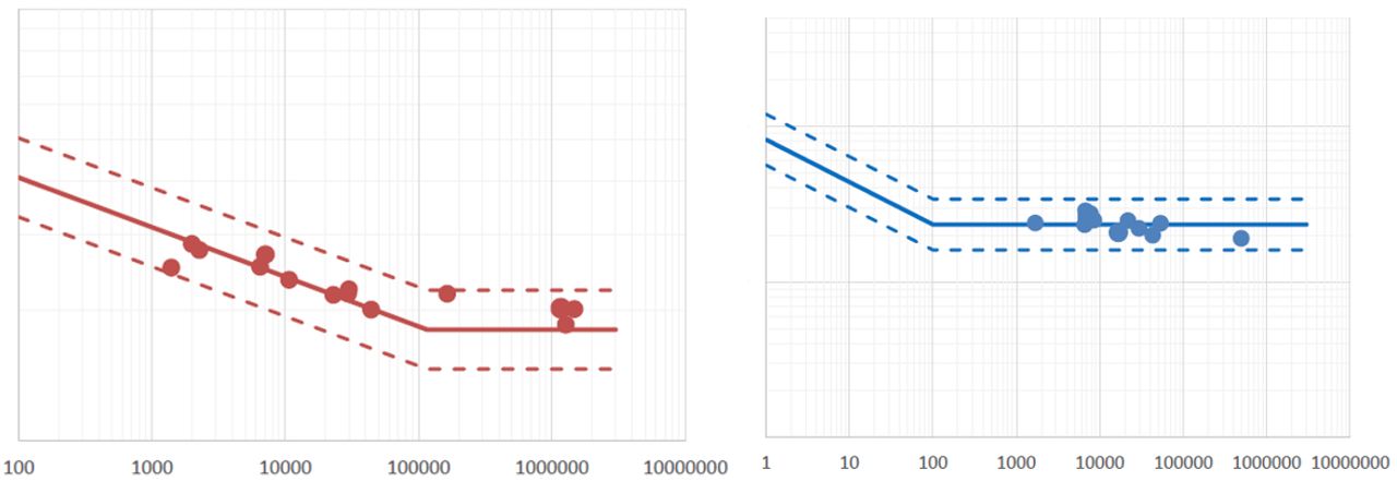
Figure 4. Statistically fitted SN curves in fiber direction (left) and transverse direction (right) based on load-controlled constant amplitude fatigue experiments completed on UD CF/PAEK specimens. Photo Credit: Econ Engineering
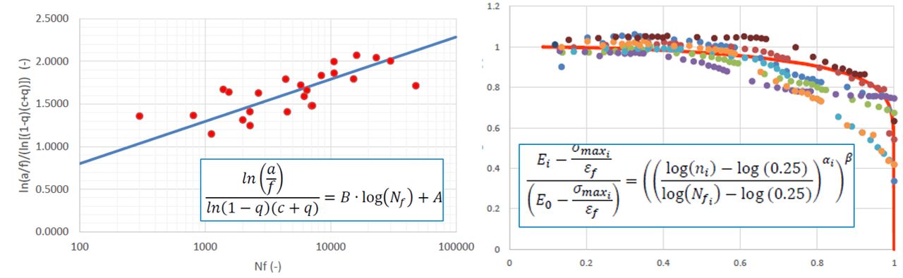
Figure 5. Haigh-diagram parameter fitting (left) and degradation law parameter fitting (right) based on load-controlled constant amplitude fatigue experiments on UD CF/PAEK specimens. Photo Credit: Econ Engineering
The FE-based methodology for cyclic strength assessment developed by Econ Engineering has been validated by physical testing on continuous carbon fiber-reinforced (CF) thermoset (epoxy) and thermoplastic (PAEK) composite laminates under loading in fiber and transverse directions at different R-ratios with good results. As a complementary feature, parameter fitting methods have also been elaborated to find the constants of the fatigue model based on load-controlled constant amplitude fatigue experiments done on unidirectional (UD) standard plate samples. The fitting process includes maximum likelihood method-based SN curve fitting for life distribution prediction (Fig. 4) as well as the evaluation of the Haigh-diagram and strength degradation model constants in different loading conditions (Fig. 5).
Application example
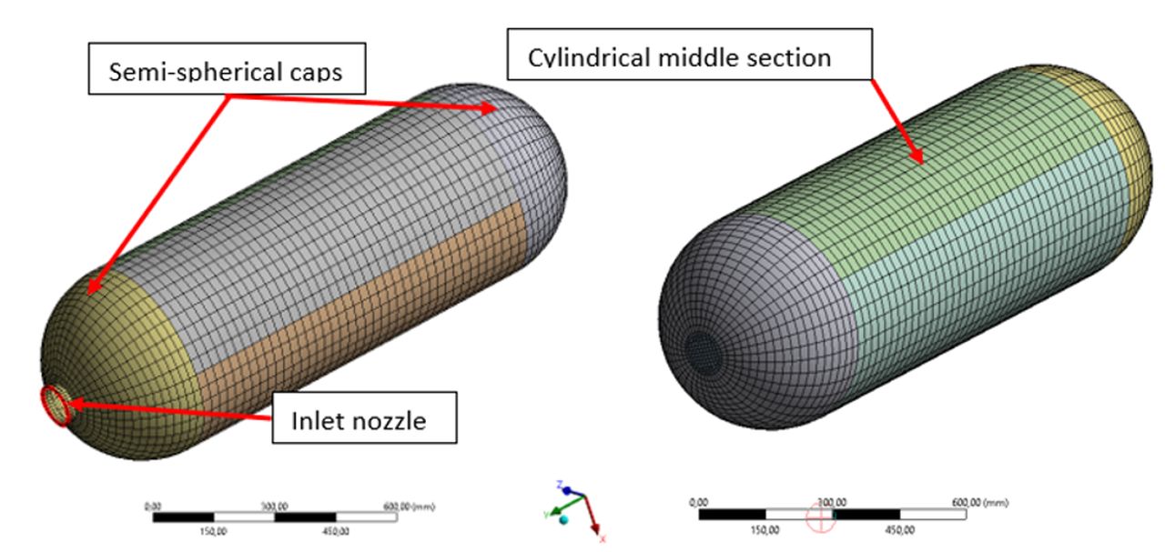
Figure 6. FE model mesh for a CF/PAEK composite pressure vessel application, used as an example. Photo Credit: Econ Engineering
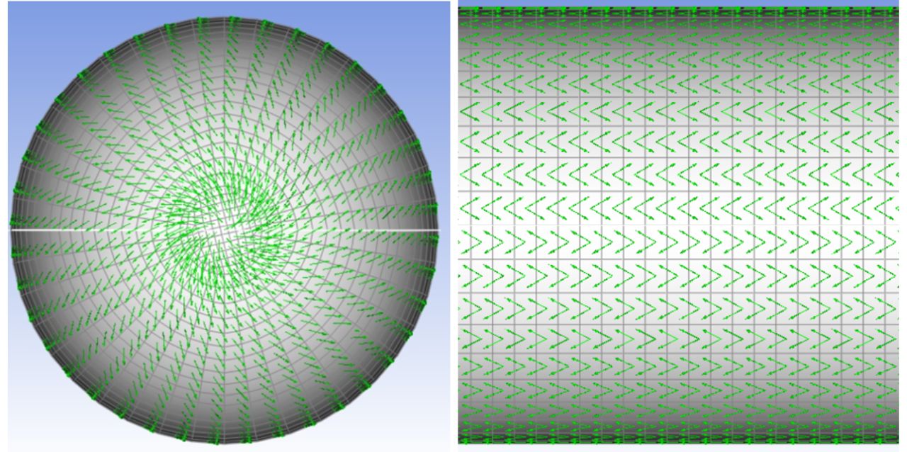
Figure 7. Local fiber orientations of the +/-30° composite plies in the CF/PAEK pressure vessel body. Photo Credit: Econ Engineering
An FE simulation of a UD CF/PAEK pressure vessel — e.g., for storing compressed hydrogen gas — was performed with subsequent fatigue analysis. The simulation model was constructed in the Ansys Workbench environment using layered shell elements. The Ansys Composite PrePost tool was used to automatically define the draped layer orientations based on the ply layup sequence specified for the dry reinforcement. The meshed model and the fiber orientations are shown in Fig. 6 and Fig. 7. A standard layup of [+/-30°] was used along the entire model which is typical for such filament-wound structures. It was extended with an additional hoop (90°) reinforcement layer in the cylindrical middle section. A linear orthotropic material model was assumed with the standard moduli of the CF/PAEK composite material that was subjected to previous static and fatigue mechanical testing.
The fitted fatigue model constants were implemented in the subsequent fatigue assessment. The tank was loaded by a constant overpressure from inside while it was constrained at its boss (inlet nozzle). The pressure loading was assumed to fluctuate between zero and a maximum pressure of 20 bar, representing a filling-operation-depletion lifecycle. Note, this was only an example to show how to use the methodology, not an actual validation, which would require much higher pressure (e.g., 700 bar).
In the initial static assessment in the cylindrical section, a roughly 20% stress utilization was calculated, which increased up to 70% over the fatigue assessment. At this high level of utilization, the fatigue assessment predicted accelerated damage increase, thus the onset of cracking was anticipated, and the fatigue analysis was stopped. The cause of the failure was cracking in the fiber direction which is a showstopper since that would lead to a catastrophic burst of the tank. The adaptive cycle incrementation required 32 iterations comprising 3,540 real cycles, which is the declared fatigue life of the composite gas tank.
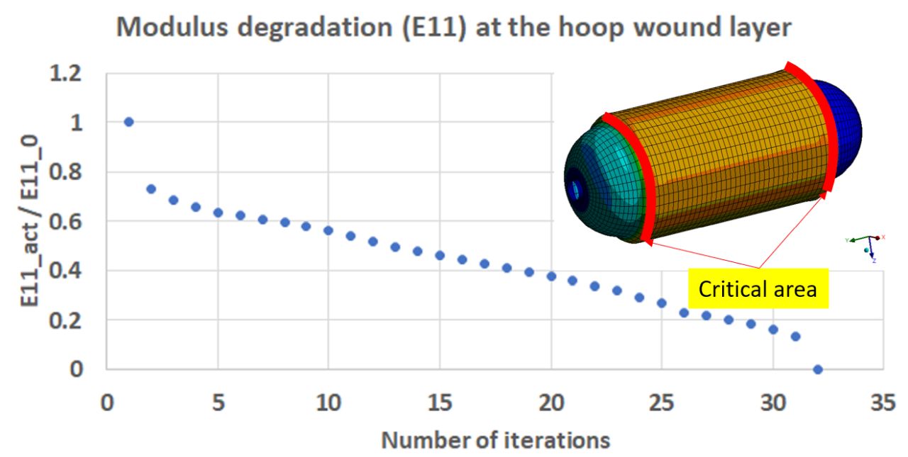
Figure 8. Predicted modulus degradation process of the critical area over successive fatigue iterations (at the hoop layer). Photo Credit: Econ Engineering
Fig. 8 shows the degradation process of the E11 modulus over successive cycles along with the deformed shape of the tank under maximum internal pressure. The critical area of the tank was the transition zone between the end cap and cylindrical middle section due to extensive bending caused by the internal load. The ply experiencing the highest load turned out to be the 90° (hoop) layer because that is the layer that resisted the high membrane hoop stress caused by the internal pressure in the tank.
The methodology presented here was published in the April 2020 issue of Engineering Failure Analysis (IF=4.0) . Econ Engineering continues to develop this method and is performing fatigue testing of thermoplastic composite materials for suppliers as well as related design engineering for a variety of applications and customers.
References
1V.A. Passipoularidis, T.P. Philippidis, P. Brondsted: “Fatigue life prediction in composites using progressive damage modelling under block and spectrum loading.” International Journal of Fatigue, Vol. 33 (2011), pp. 132-144, https://doi.org/10.1016/j.compositesb.2017.06.021
2Daniel Kowollik, Fabio Pavia: “Blade Fatigue Assessment at Bewind Is a Breeze.” Ansys Advantage, Vol. 16 (2022), ansys.com/advantage-magazine/volume-xvi-issue-1-2022/blade-fatigue-assessment-at-bewind-is-a-breeze
3Caous D., Bois C., Wahl J-C., Palin-Luc T., Valette J.: “A method to determine composite material residual strength in the fiber direction as a function of the matrix damage state after fatigue loading.” Composites Part B: Engineering (2017), 127, pp. 15-25 https://doi.org/10.1016/j.compositesb.2017.06.021
4A. Puck, H. Schürmann: “Failure analysis of FRP laminates by means of physically based phenomenological models.” The World-Wide Failure Exercise (2004).
About the Author

László Kovács
László Kovács is a senior simulation engineer and R&D coordinator at the Hungarian company Econ Engineering. Before joining Econ in 2017, he worked in the turbomachinery industry, mainly focusing on lifespan assessments and method development for critical structural parts of steam turbines and aerospace jet engine rotating components. He has more than 15 years of experience in strength assessment techniques supported by FE modeling. After graduation, Kovács spent 5 years at Siemens Energy as an advanced structural analyst and 5 more years at Rolls-Royce Plc, Civil Large Engines Sector, Rotatives SCU as principal lifing technologist. He has developed special knowledge in mechanical testing, nonlinear material modeling (metals, polymers, polymeric composites) and damage modeling (especially fatigue approaches), and is completing his Ph.D. at Budapest Technical University on the topic of numerical material model characterization of continuous fiber-reinforced plastics.


Related Content

Manufacturing the MFFD thermoplastic composite fuselage
Demonstrator’s upper, lower shells and assembly prove materials and new processes for lighter, cheaper and more sustainable high-rate future aircraft.
Read More
PEEK vs. PEKK vs. PAEK and continuous compression molding
Suppliers of thermoplastics and carbon fiber chime in regarding PEEK vs. PEKK, and now PAEK, as well as in-situ consolidation — the supply chain for thermoplastic tape composites continues to evolve.
Read More
One-piece, one-shot, 17-meter wing spar for high-rate aircraft manufacture
GKN Aerospace has spent the last five years developing materials strategies and resin transfer molding (RTM) for an aircraft trailing edge wing spar for the Airbus Wing of Tomorrow program.
Read More
The state of recycled carbon fiber
As the need for carbon fiber rises, can recycling fill the gap?
Read MoreRead Next

FASTIGUE: Empowering digital twins of large-scale composite structures
A 3D finite element technique to resolve the fidelity-versus-speed dilemma of performing fatigue analysis for large composite structures.
Read More
Fatigue testing of composites
Fatigue testing may be performed at multiple points during the design of a composite structure. A focus on small-specimen level fatigue test methods, however, suggests a need for more testing method standardization.
Read More
On the radar: Cryogenic testing of composites for future hydrogen storage
Netherlands, U.K., France, Germany and the U.S. build up test capability, look at thermoset and thermoplastic composite materials.
Read More