
FASTIGUE: Empowering digital twins of large-scale composite structures
A 3D finite element technique to resolve the fidelity-versus-speed dilemma of performing fatigue analysis for large composite structures.
Share
Read Next


As offshore wind farms evolve into systems with soaring complexity, digital twins of the individual composite rotor blades will revolutionize the industry by providing real-time performance predictions coupled to a structural health monitoring feedback loop. This is especially important for high-growth offshore wind turbines, where maintenance is challenging and expensive.
Fatigue prediction makes digital twins computationally demanding
A prominent challenge for such digital twins, and their ability to improve the operation of large-scale composite structures, is the prediction of fatigue failure. Typically, this failure is due to progressive material degradation induced by the millions of recurring mechanical and thermal load cycles a composite blade experiences during its 20- to 25-year life. The integration of such fatigue prediction capabilities into digital twins increases the computational load and, thus, the need for computational speed — preferably without compromising accuracy. However, the nemeses of real-time fatigue-life prediction methods for large structures are numerous, including highly dynamic (quasi-stochastic) loading conditions, intricate component geometries, anisotropic material behavior and structural nonlinearities. All of these increase complexity and decrease computational speed.


Appropriate consideration of these important effects and their interplay, then, compels the use of full-scale, 3D finite element models. The next hurdle is to bridge several orders of magnitude between characteristic length scales. At the macroscopic level, for such analysis to be efficient, it must discretize (break up into smaller elements) blades with a characteristic length of 100 (1×10²) meters. And yet, the physical damage process must be resolved on a microscopic level with a characteristic length of <1×10⁻⁵ meters. Continuum damage-based fatigue models do bridge this gap by smearing over these scales using phenomenological considerations — in other words, where responses are prescribed by force and deformation relationships and related to geometry. In contrast, fracture-based fatigue models are renowned for providing both more information (e.g., discrete cracks comply better with damage inspection) and a higher degree of accuracy. Thus, they are often the preferred choice.
However, these fracture-based models require discrete crack modeling approaches, which necessitate high mesh discretization levels at the crack tip, resulting in models with high computational demand. Even sub-modeling (breaking up large structures into simultaneous modeling of substructures) hardly manages to tip the balance. Such highly discretized models are manageable for monotonic loading, where the load is applied in one direction and increased to determine yield and failure such as in tension and compression testing. But this falls short for analysis of high-cycle fatigue loading, where classic “update-and-rerun” approaches require that the crack tip be consecutively updated (e.g., adaptive re-meshing), followed by re-run of the 3D model for a considerable number of load cycles, N. With N approaching several million, computation times become impractical. Thus, despite the availability of advanced discrete fatigue simulation models, their application to large composite structures is largely unfeasible.
FASTIGUE resolves heavy computational demands
This, then, is the problem: fatigue analysis of large structures presents a fidelity-versus-speed dilemma. In pursuit of a solution, Dr. Martin Eder and Dr. Xiao Chen, researchers at Technical University of Denmark (DTU, Risø Campus), have recently developed a super-efficient discrete fatigue crack growth simulation approach, coined FASTIGUE, for large-scale structures such as composite wind turbine blades. FASTIGUE is based within the classic realm of fracture-based fatigue analysis but trades some general applicability for a significant gain in computational speed. The specialized approach puts forth a set of empirically-corroborated assumptions that facilitate the decoupling of the finite element analysis from the crack-growth analysis procedure. In other words, the computationally demanding fracture analysis is outsourced into a pre-processing module while the crack-growth simulation is conducted subsequently and independently in a separate fatigue analysis module (Fig. 1).
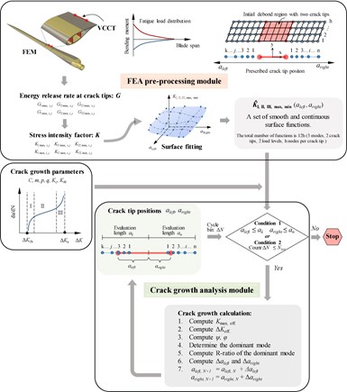
Fig. 1. Flow chart of the proposed FASTIGUE approach comprising an FEA pre-processing module (top) and a crack growth analysis module (bottom). Gray arrows indicate the computational flow, showing that feedback between the FEA pre-processing module and the crack growth analysis module is avoided, resolving heavy computational demands of fatigue crack simulation for large structures such as composite wind turbine blades. Source | Martin Eder, Xiao Chen, DTU Risø
This approach pertains to specific situations in which (1) the crack propagation path is predefined and (2) the variation of the fracture parameters is quasi-uniform along the crack front. Cracks in the adhesive bondline along the trailing edge of composite wind blades provide a good example — indeed, they propagate along the bondline in a fairly uniform manner. This has been empirically corroborated by small-scale fracture tests as well as large-scale blade tests and is explained by the large bondline width-to-length aspect ratio of ≈1:500 (or larger).
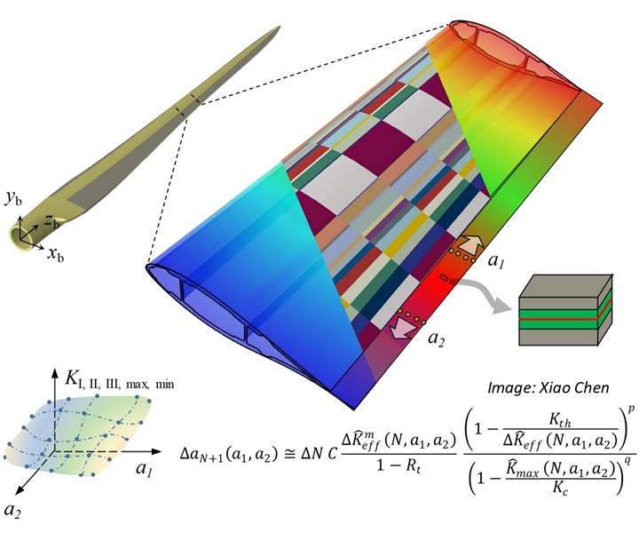
Upon introducing an initial through-crack into an arbitrary location along the bondline of the structure, the fracture parameters (e.g., the stress intensity factor, K) can be computed in both crack tips for a number of user-defined crack lengths on both sides denoted as a1 and a2 (Fig. 2), allowing an entire possible solution domain to be constructed by surface fitting in a pre-processing step (Fig. 1).

Fig. 2. In FASTIGUE, an initial through-crack is introduced at an arbitrary location along the bondline of a 3D finite element wind blade model. The crack proceeds away from this point in both directions along the bondline at the blade’s trailing edge. The fracture parameters (e.g., the stress intensity factor, K) can be computed in both crack tips for a number of user-defined crack lengths on both sides denoted as a1 and a2. Source | Martin Eder, Xiao Chen, DTU Risø
Since the fracture parameters between the two crack tips influence each other, the fracture analysis in this pre-processing step ought to be conducted for all linear combinations of the number of auxiliary crack tip positions chosen. Still, the number of runs in this step is significantly smaller than the number of runs involved in the classic fatigue analysis scheme. Thus, this approach requires significantly less computation time. Also, it is straightforward to fit a smooth 3D interpolation surface through these auxiliary points, providing the fracture parameter as a continuous function of the crack tip positions denoted as Ka1,a2. It needs to be emphasized that the spacing between these auxiliary crack tip positions is independent of the fatigue growth analysis. Any desired discrete crack growth within the possible solution domain defined by the fitted surface can be analyzed.
Once the surface fitting functions of Ka1,a2 are established, the actual crack growth analysis is performed independently by adopting any suitable discrete crack growth law defining the crack growth speed as a function of the prevailing fracture parameter state in both crack tips. In essence, under the proviso of the assumptions posited, a per-se demanding 3D fracture problem is reduced into a pseudo 1D problem described by a set of two coupled first-order ordinary differential equations (ODEs) of the generic form da1,2/dN=CK(a1,a2)m where C
Since the function Ka1,a2 is already established for the entire growth domain, the fatigue growth analysis no longer involves finite element analysis and the computational effort boils down to solving a coupled initial value problem for an arbitrary initial crack length configuration. Owing to the computational efficiency of the adopted explicit time integration schemes, crack growth analyses can be conducted in a fraction of the computation time required for classic “update-and-re-run” schemes.
Flexibility and validation of FASTIGUE approach
FASTIGUE was validated against a crack-in-a-rod analytical solution with good agreement between its predictions compared to those obtained from a high-fidelity finite element analysis. It was demonstrated that FASTIGUE offers a robust and efficient tool for predicting the fatigue crack propagation in the trailing edge adhesive joint of a full 3D finite element wind turbine blade model.
FASTIGUE can be run in two different modes: it provides the crack extension of the crack tips for a given cycle number and, conversely, provides the cycle number for a given crack extension. It is noteworthy to mention that FASTIGUE can be endowed with any desired discrete crack growth law. Moreover, the growth of multiple cracks present in the structure can be considered.
This tool was specifically developed for its integration into digital twin systems and particularly lends itself for use in reliability-based inspection planning schemes and Monte Carlo simulations, which can be conducted for a large variation of growth parameters and initial flaw sizes. This shows just the beginning of its potential for application in large-scale structures such as composite wind turbine blades and beyond.
This research is published in the Digital Twin Special Issue of Engineering Fracture Mechanics, vol. 233, June 2020. It is supported by DARWIN: Drone Application for pioneering Reporting in Wind turbine blade Inspections, Innovation Fund Denmark (6151-00020B), and RELIABLADE: Improving Blade Reliability through Application of Digital Twins over Entire Life Cycle, EUDP (64018-0068).
About the Author

Dr. Martin Alexander Eder
Senior research scientist at Technical University Denmark, Eder earned his doctoral degree, after several years in international industy, in 2011 in earthquake engineering at Imperial College (London, U.K.). He continued there as a postdoctoral researcher before joining DTU Wind Energy in 2012. In 2018, he obtained another MSc degree in materials and manufacturing engineering at DTU.
Eder’s research spans experimental and theoretical topics in computational non-linear fracture mechanics of composite materials, discrete and continuum damage-based fatigue prediction methods, nonlinear stability analysis of structures and novel approaches for component scale and full-scale testing methods. Eder has been project- and work-package leader of industrial research projects (EUDP) such as IMPACT and WindWeld, supervisor for industrial Ph.D. students (Innovation Fund Denmark) and a postdoc, and has authored and co-authored more than 20 publications in a range of applications.

Dr. Xiao Chen
Associate professor at Technical University of Denmark, Chen received his doctoral degree in structural engineering in 2011 from Nagoya University in Japan and worked as a postdoctoral research fellow in the National Wind Energy Center at the University of Houston, Texas, U.S. From 2013, he served as assistant professor and then associate professor at Chinese Academy of Sciences in Beijing before he joined DTU in 2017.
Chen is work package leader in the DARWIN project funded by the Innovation Fond of Denmark, and also for the RELIABLADE and RELIFE projects, both supported by the Danish Energy Agency through the Energy Technology Development and Demonstration Program (EUDP). He has authored more than 20 journal articles and supervises Ph.D. students and research in advanced testing and high-performance modeling of large composite structures focusing on structural integrity and digitalization.


Related Content

Trends fueling the composites recycling movement
Various recycling methods are being considered for composites, from novel dismantling and processing, to building capacity and demonstrating secondary use applications.
Read More
SRI develops scalable, infiltration-free ceramic matrix composites
Work in two DOE projects is demonstrating C/C-SiC produced in 3-5 days with <5% shrinkage, <10% porosity and 50% the cost of conventional C/C and C/C-SiC.
Read More
Plant tour: Hexagon Purus, Kassel, Germany
Fully automated, Industry 4.0 line for hydrogen pressure vessels advances efficiency and versatility in small footprint for next-gen, sustainable composites production.
Read More
Honda begins production of 2025 CR-V e:FCEV with Type 4 hydrogen tanks in U.S.
Model includes new technologies produced at Performance Manufacturing Center (PMC) in Marysville, Ohio, which is part of Honda hydrogen business strategy that includes Class 8 trucks.
Read MoreRead Next

Sentherm conductive polymers match aluminum thermal performance, cut weight
Tailored filler networks, anisotropic material design and manufacturing process control achieve hybrid polymers for EVs, batteries and other automotive-related electronics with 95% of aluminum’s thermal performance and 25-45% reduced component weight.
Read More
Kaneka BMI material attains >25% lead time, >20% tool cost reductions in Janicki evaluations
Process evaluations find that novel BMI polymer chemistry addresses longstanding manufacturing challenges of BMI tooling prepregs while maintaining high temperature performance and durability.
Read More
Polestar 5 takes aesthetics and circularity approach to biocomposite seatback design
The 2026 Polestar 5 expands the company’s use of sustainable materials design in the interior, including flax fiber/thermoplastic seatbacks that save 7 kilograms of weight and reduce overall plastics use.
Read More