
High-speed press cure for high-speed racers
Trapped tooling and compression molding bring cocuring efficiencies to previously autoclave-cured, aerodynamic fins and planes.


Swift Engineering Inc. (San Clemente, Calif.), the exclusive chassis supplier for the Formula Nippon (Japan) race series, manufactures parts for 16 cars on the circuit, including replacement aerodynamic fins and wings molded from carbon fiber composites. Source: Swift Engineering
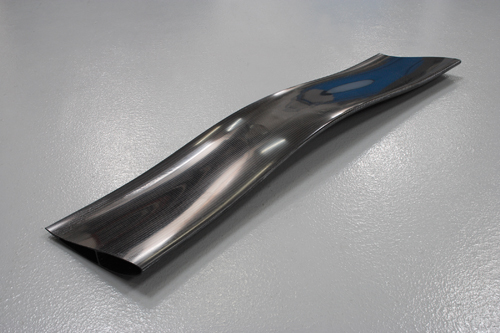
A completed fin shows its Class A surface. Source: Swift Engineering
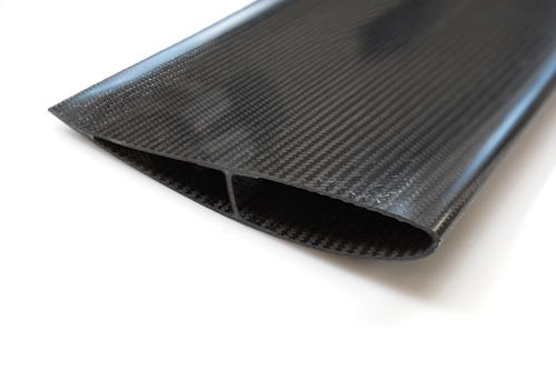
The open end of the fin, which is eventually capped, reveals the unitized spar. Source: Swift Engineering
Step 1: Two plies of ACG VTM 260 series carbon fiber prepreg are placed in the aluminum tool and debulked. Source: Swift Engineering
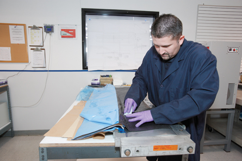
Step 2: Using a cardboard template, the first center spar is cut and placed in the middle of the tool. Source: Swift Engineering
Step 3: The first center spar, in place. Source: Swift Engineering
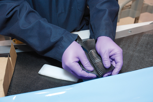
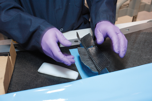
Step 4: Silicone intensifiers, wrapped with blue release film, are prepared for placement in the tool. A ply of prepreg is placed around its thickest edge. Source: Swift Engineering
Step 5: The prepreg wrapped around each edge of the intensifiers will become the lengthwise spar in the fin structure. Source: Swift Engineering
Step 6: Silicone intensifiers are abutted to create the I-shaped spar and then nested in the tool. The intensifiers provide support for the spar prepregs during press-cure. Source: Swift Engineering
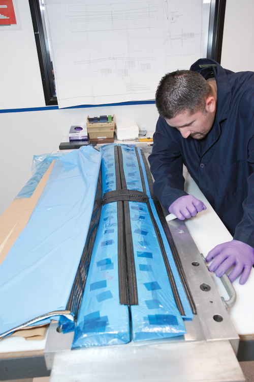
Step 7: Prepreg for the leading edge is placed between the larger silicone intensifier and the outer mold edge. Source: Swift Engineering
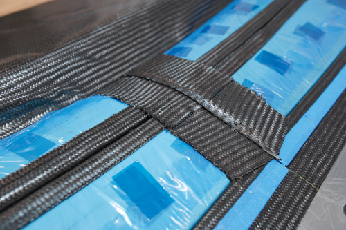
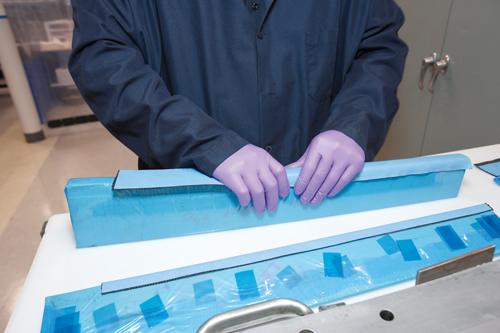
Step 8: Once all silicone intensifiers and prepreg are in place, the center spar flaps are folded flat. All of the spars and skins will be unitized during cocure in the press. Source: Swift Engineering
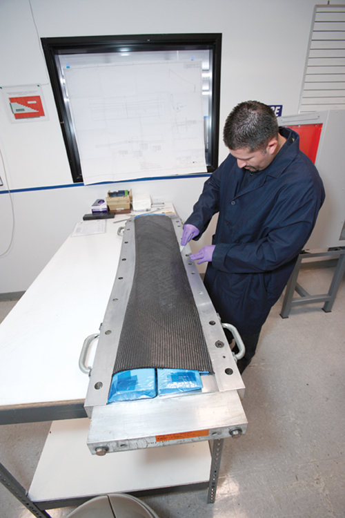
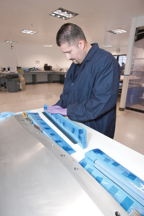
Step 9: The prepreg plies are folded over the entire spar/silicone structure to form the top skin of the fin. Source: Swift Engineering
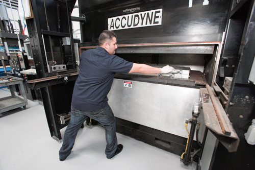
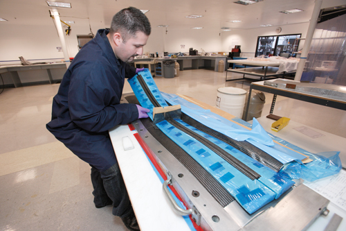
Step 10: The closed tool is placed in a heated-platen press. It ramps up to 300°F/149°C and down to take-out temperature in about 60 minutes. Source: Swift Engineering
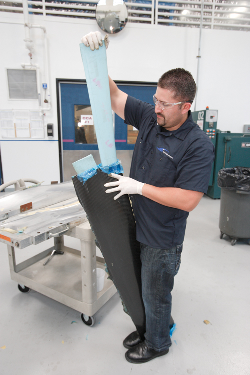
Step 11: After press-cure, the fin is removed from the mold and silicone intensifiers are pulled out of the part. Source: Swift Engineering
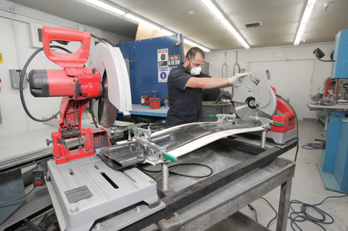
Step 12: The finished fin is placed in a holding fixture and the ends are sawed off to cut the fin to specified length. Source: Swift Engineering


Although they are highly engineered and ultra-aerodynamic, composite structures for Formula race cars aren’t designed for lengthy product life cycles. They’re built under the assumption that they will, at some point in the near future, be damaged or destroyed. This design and application paradigm is unique in the composites manufacturing industry. Short product life and equally short development cycles encourage experimentation that is not possible elsewhere in the composites community.
This fertile, aggressive development environment is part of the status quo at Swift Engineering Inc. (San Clemente, Calif.), the exclusive chassis supplier for the Formula Nippon (Japan) race series. Each race season, Swift supplies the structural components for all 16 cars on the circuit. Each driver uses the same chassis for two seasons, but other components suffer damage during incidental collisions that occur during races. This is especially true of the carbon fiber composite fins, planes and flaps that govern the car’s aerodynamic performance. Swift provides replacements for these components throughout the season, averaging several shipsets per month.


This short-run, fast-turnaround environment led to the development of a rare manufacturing method that Swift hopes has applications beyond Formula racing.
“Motorsports is a great vehicle for exploration,” says Stuart Marshall, senior manufacturing engineer and plant manager at Swift. Rick Heise, programs director at the company, says, “Necessity has created what’s required to innovate and try new technology.”
Necessity and her son, invention
The fins and planes — in essence, small wings — provide lift or downforce on the vehicle, depending on the part’s location on the car. Like a wing, each fin and plane has a spar structure sandwiched between two aerodynamically designed carbon fiber skins. Previously, these bagged and autoclave-cured structures were manufactured in three parts — upper and lower skins and the spar. The skins were bonded to the spar post-autoclave. “The problem with this design,” says Marshall, “is that all the loads were on the paste adhesive.” Most failure modes of planes and fins, therefore, began at bondlines. The obvious solution? Cocure the skins and spar in a single mold and mold cycle.
As Swift assessed the cocure concept and the process that would be required to accomplish it, designers identified several opportunities for part improvement. The result was a complex set of goals: Cocure the components, reduce cycle time, eliminate the production bottleneck as components wait to be autoclaved, reduce touch time and improve part quality consistency.
Getting out of the autoclave, says Marshall, proved to be the easiest goal to reach. Swift’s established relationship with Advanced Composites Group Inc. (ACG, Tulsa, Okla.) provided early access to that firm’s out-of-autoclave prepreg series, including VTM 260, VTM 240 and MTM 49.
The bigger challenges were how to mold the fins and planes in one piece and how to generate the in-mold pressure required to properly consolidate the plies in a press-forming process. The solution to both problems was provided by a single device. Marshall recalled a tried-and-true but low-tech technique, the use of silicone tooling inserts, and wondered if they could do more than merely provide structural support for carbon fiber prepreg inside the tool. “Silicone foam, under high heat, expands,” Marshall explains. “The revolutionary thing we did was to use that expansion to provide pressure inside the mold to consolidate the laminates.” Notably, the silicone expansion concept worked so well that the tonnage of the compression press wasn’t necessary to ensure the success of the process. “We decided to use the press to simply close the tool, but not to provide part pressure,” he notes.
Powerful blue silicone
Today, fabrication of a fin or plane at Swift starts with the lower half of a two-part aluminum mold, made in-house. Large components, such as the 6.5-ft/2m rear fin, are produced in one tool. Smaller parts can be ganged and number as many as 30 in a tool. The assembly illustrated here (and in the step photos at right) is a fin about 4 ft/1.2m long, which consists of a top and bottom skin with two perpendicular spars. One spar travels the length of the fin along its center, and the other runs along the width of the fin, also at its center. Its interior, therefore, consists of four quadrants, each separated by a structural spar.
The trick is to assemble all of the prepreg for this structure in a way that maintains proper positioning of the skin and spars, allows for cocure of all prepreg and produces a completely unitized structure. “These parts are designed to provide specific aerodynamic functions on a car,” says Marshall. “The consistency of their quality and strength is vitally important.”
To begin, the tool is lined with two plies of ACG’s VTM 260 series out-of-autoclave carbon fiber prepreg for the bottom skin. These plies are twice the width of the fin; excess material flows past the mold edge and will, eventually, be folded over to form the fin’s top skin. On top of the bottom skin, depending on the part, Swift may strategically place ROHACELL foam core provided by Evonik Foams Inc. (Magnolia, Ark.). The cores, says Marshall, aren’t needed in service — the fin achieves the required stiffness without them — but they provide support during molding for the spar sections in fully enclosed cells within the fin or plane.
Placed next is the I-shaped centerline spar. This prepreg structure, positioned perpendicular to the bottom skin, traverses the skin across its width. Then, the silicone intensifiers are prepared for placement. This low-density foam, provided by Silpak Inc. (Pomona, Calif.), is cast by Swift in molds that the company either builds with a 3-D printer or shapes from tooling board. The intensifiers are designed to assume the shape of the noncomposite space within the fin/plane, thus occupying the gaps between the just-placed spar and the skins. The intensifier’s size depends on the shape and size of the part and the amount of pressure intensification required for the application. Larger silicone pieces experience greater expansion and, as a result, apply greater pressure. Each intensifier is wrapped with a blue release film to prevent foam/prepreg adhesion.
The fin shown in the step photos uses four relatively large intensifiers, each of which measures about 18 inches/455 mm long and 1 inch/25 mm wide at its base, with the other edge tapered to about 0.25 inch/6.5 mm. A strip of prepreg as long as the intensifier but about 2 inches/50 mm wider is wrapped around the wider edge of each intensifier. Two such intensifiers are then mated by abutting the wide ends together; the adjoining prepregs of each intensifier will form the I-shaped spar that runs the length of the fin.
Like a puzzle, one mated pair of intensifiers is nested on one side of the already-placed centerline spar, and the other pair is placed on the other side. The narrower edge of each intensifier faces the outer mold edge and provides the fin’s contoured shape. Another prepreg-wrapped strip of silicone is placed along this edge, to form the leading edge.
When the intensifiers are in place, the width-wise spar flaps are folded down to complete the spar’s I-shape. Then, the two skin plies are folded over the entire assembly and debulked to form the top skin prior to mold closure and cure.
Marshall notes that one of the benefits of this tooling system is how well its components work together. Caul plates along the tool’s edge provide the rigidity required at that location to maintain prepreg positioning. Inside the tool, the intensifiers nest easily into place and ensure the structural integrity for the spars.
He also reports that data from extensive trial-and-error work with the silicone has provided the company with significant knowledge about intensifier expansion during molding. Marshall says it is thus necessary to “calculate an offset gap between intensifiers based on the known growth of silicone.” Early tests, he said, revealed expansion rates of about 0.020 inch/0.5 mm. However, as Swift experimented with more shapes and sizes of silicone, expansion rates were fine-tuned and more precisely determined, allowing for better control of pressure regimes.
Short-cycle press cure
When the structure is ready for compression and cure, the top mold half is attached to the bottom, and the assembly is placed in a heated-platen compression press provided by Accudyne Engineering & Equipment Co. (Bell Gardens, Calif.). Because consolidation pressure is provided by the intensifiers, the primary job of the press is to keep the mold closed, pull a vacuum and provide cure heating. Swift saw the latter function as another opportunity to speed the cycle time and developed a heated-platen system that takes the entire mold up to 300°F/149°C and back down to take-out temperature (about 160°F/71°C) in just 60 minutes.
Marshall says the steep temperature profile could stress the fin’s carbon fiber and, thus, compromise part integrity, particularly if cooling is too rapid. By pulling the tool from the press at a relatively high temperature, the cooling cycle of the fin is slowed and molded-in stress is avoided.
After the tool is pulled, the remaining steps are simple: The intensifiers, are manually pulled from each end of the fin. After the fin’s ends are cut to final dimension with a circular saw and capped, the fin is ready for shipment.
Marshall reports that the fins and planes coming out of this compression process feature a Class A surface and are ready for immediate installation on a race car. “These wings and fins take more downforce than the autoclave version,” Marshall adds. “They are less likely to fail in other than a crash situation, and this leads to less use of spares.”
This manufacturing technology continues to evolve, says Marshall. Swift is evaluating its use for bigger, more sophisticated parts. The company also is experimenting with more use of ROHACELL core. The challenge is that its pressure profile is different than that of the silicone, thus the core must be oversized when it is used in the press-cure process. The company also has begun to mold-in fastener holes to eliminate the risk of damage during drilling.
Pressure optimization, other markets
This new application of old technology has helped Swift meet all of its Formula Nippon fin and plane production goals. Further, it involves minimal use of consumables (blue release film is the only waste product) and avoids some of the challenges of bagging for the autoclave process. Accordingly, the company now is thinking seriously about how silicone-trapped tooling and compression molding might be applied elsewhere, with an eye on aerospace applications. Swift developed the Killer Bee unmanned aerial vehicle (UAV). Although it was sold to Northrop Grumman in 2009 and renamed the Bat, Swift retained manufacturing and produc-development responsibility for the military contractor.
“The question,” says Marshall, “is how do you validate this pressure process to make sure it’s going to give you the pressure you expect?” Working this process into aerospace applications will require robust validation and a level of pressure control not demanded by motor sports applications. “We know the structures we currently make meet the requirements of the load, so that’s validating,” says Marshall. “But we are not at a point where we can say definitively that a silicone intensifier of a certain thickness will generate a certain pressure at a certain temperature.”
To that end, Swift is experimenting with the use of mandrels around which a fixed thickness of silicone intensifier is wrapped. The assumption is that a consistent layer of foam will generate consistent pressure when it is elevated to a certain temperature. “In aerospace, control of the IML [inside mold line] and OML [outside mold line] is critical to creating a predictable part thickness,” notes Marshall. “We’re looking to meet ASTM and Nadcap standards.”
Marshall says Swift has, so far, successfully used the press-cure process to mold a UAV winglet and a UAV propeller that features ROHACELL foam core molded into each blade. Other applications are in development.


Related Content

Active core molding: A new way to make composite parts
Koridion expandable material is combined with induction-heated molds to make high-quality, complex-shaped parts in minutes with 40% less material and 90% less energy, unlocking new possibilities in design and production.
Read More
Troubleshooting thermoplastic composite stamp forming
Understand the basic science of TPC stamp forming, a manufacturing process steadily gaining momentum in aerospace and mobility applications thanks to its rapid forming, short cycle times and automated methods.
Read More
Advancing mold release technology for aerospace composites manufacturing
Chem-Trend’s water-based, silicone-free mold release agent eliminates release curing time and provides easy tool cleanup.
Read More
KAI demonstrates thermoplastic and infused structures for future airframes
Korea Aerospace Industries advances its expertise through a welded TPC fuselage section and resin-infused wing skin module and torsion box demonstrators.
Read MoreRead Next

Dialing in composites performance via dynamic digital twins
Sport Dynamics Lab uses Flexdynamics testing, digital models and AI tools to compare designs, materials and systems, enabling optimization with potential for propellers, drones and vibrational structures.
Read More
Report: Composites and Carbon Fiber Use in Hydrogen Storage
A first-of-its-kind technical report that assesses the materials, manufacturing processes, market and energy trends driving use of carbon fiber composites in global hydrogen (H₂) storage applications for fuel cell-powered trucks, buses, trains and passenger vehicles.
Read More
Industrial ultrasonic NDT adaptation permits accessible composite bicycle inspection
Cycle Inspect's ASNT-aligned certification program employs affordable twin-crystal ultrasonic testing equipment and standardized inspection methods to detect damage in composite bicycle components.
Read More