
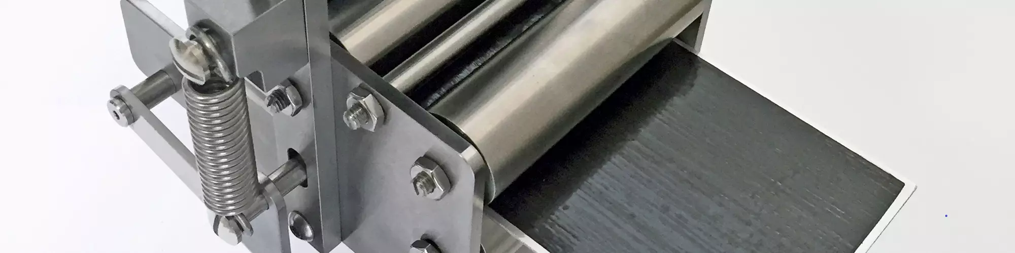


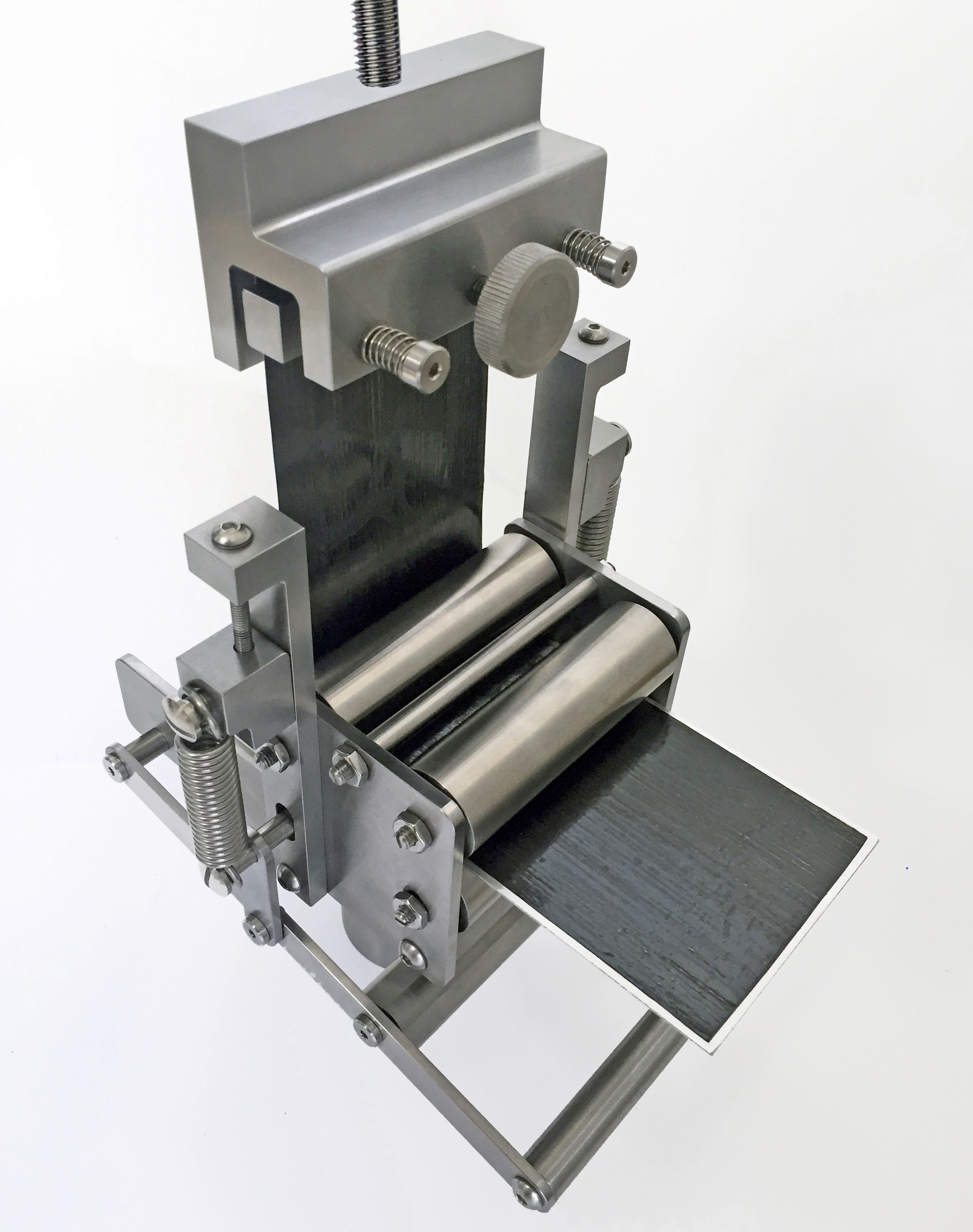
Fig. 1. Prepreg tack test fixture with specimen installed. Photo Credit: Wyoming Test Fixtures
Prepreg tack testing refers to measuring the “stickiness” of thermoset composite prepreg materials used to fabricate composite structures. These prepregs consist of a thin layer of fiber reinforcement pre-impregnated (prepregged) with a polymer resin, such as epoxy. The prepreg is partially cured so that the resin is a tacky solid at room temperature, a state referred to as B-staged. Typically, such prepregs are covered with a protective film and stored in rolls in freezers to significantly slow further curing of the resin. As the prepreg continues to cure, its surface tack continues to decrease. Therefore, even when kept frozen, composite prepregs typically have a limited shelf life. The level of tack is important when fabricating composite structures, particularly when using automated prepreg layup processes such as automated fiber placement (AFP) and automated tape laying (ATL).
Test results from this prepreg tack test may be used for several purposes. For starters, the measured tack may be used for quantitative comparisons of candidate prepreg materials during the material selection process, particularly for use in automated prepreg layup operations. Tack testing may also be used as a prepreg material acceptance test and for quality control during production. Additionally, prepreg tack tends to decrease over time but increases with both higher temperatures and higher humidity levels. Therefore, test results may be used to adjust cure process parameters due to four important factors affecting lamination: pressure, temperature, humidity and time out of the freezer.


Until recently, no standardized test methods have existed for measuring prepreg surface tack. As a result, several test methods originally developed to assess the tack of pressure-sensitive adhesives have been used1. One method, known as the rolling-ball tack test, involves releasing a steel ball at the top of a ramp on which a prepreg layer has been placed. The distance that the ball travels before stopping is used as a comparative measure of prepreg tack. Additionally, fixed-diameter mandrel tests have also been used, in which a prepreg sample is wrapped around metal cylinders of specified diameters and monitored to determine whether the prepreg remains attached or pulls off the cylindrical surface. Probe-based tack tests use a tensile test machine to measure the force required to separate a prepreg layer from flat-faced, cylindrical probe surfaces after being pressed together. Finally, T-peel tests have been used, in which a two-layer prepreg specimen is peeled apart by placing the free end of the two prepreg layers into the grips of a tensile testing machine and measuring the required tensile force to peel the layers apart.
In 2021, ASTM International (Conshohocken, Pa., U.S.) standardized a new prepreg tack test, ASTM D83362 (Fig. 1), based on a modified floating roller peel test methodology developed by Crosby et al. at the University of Nottingham3. This test method is designed to represent automated composite prepreg layup processes currently used in the composites industry4. As shown in Fig. 2, tests may be performed to measure the tack between a flexible prepreg layer and either a second prepreg layer (Method I) or a rigid metal substrate (Method II). In both methods, the prepreg strip is 75 millimeters wide and at least 215 millimeters long. The rigid substrate, typically a stainless-steel plate, is 80 millimeters wide and at least 140 millimeters long. Note that in both methods, a portion of the flexible prepreg layer remains covered by the protective film, producing two different regions of the specimen for testing.
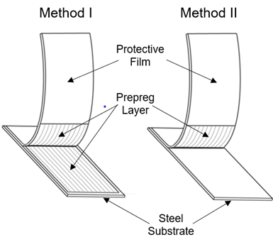
Fig. 2. Prepreg tack test specimen configurations, ASTM D8336-21. Photo Credit: Dan Adams
The prepreg tack test fixture in Fig. 1 includes two pairs of opposing 25-millimeter-diameter rollers attached to the fixture body with low-friction bearings. The front pair of rollers aligns and supports the prepreg specimen. The rear pair of rollers provides compaction to the prepreg specimen, simulating the layup process. The compaction force is applied by two springs mounted to the ends of the lower rear compaction roller. The magnitude of the compaction force may be adjusted by rotating the two jacking screws that connect the tops of the compaction springs to the fixture body. The test fixture is attached to the base of a universal testing machine and a mechanical vise grip is attached to the load cell above the fixture.
Prior to testing, a calibration procedure is required to relate the number of revolutions of the jacking screws to the applied compaction force. The calibration is performed by mounting an L-shaped steel bracket into the upper grip and positioning the short flange of the bracket directly underneath the compaction roller (Fig. 3). The two jacking screws are tightened incrementally by the same number of revolutions and the resulting force is measured by the load cell up to at least 100 newtons. A calibration curve is developed, relating the number of revolutions of the jacking screws to the resulting compaction force.
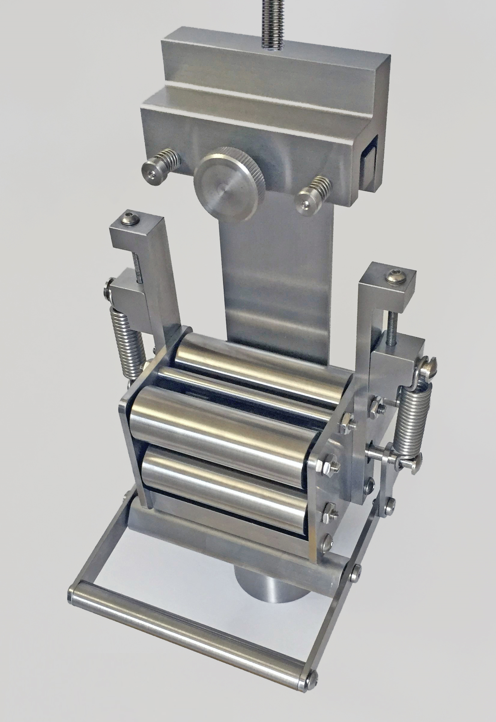
Fig 3. Test fixture calibration procedure using L-shaped steel bracket. Photo Credit: Wyoming Test Fixtures
To perform the test, the assembled prepreg specimen is inserted into the test fixture between the two sets of opposing rollers with the extended-length prepreg layer on top. This prepreg layer is deformed upward around the spring-loaded compaction roller and inserted into the upper grip. As the upper crosshead of the test machine is raised, a continuous compaction-and-peel process occurs, as the prepreg is pressed against the substrate by the compaction roller and subsequently peeled away as the specimen substrate translates horizontally through the test fixture.
The resulting force and crosshead displacement are recorded over two regions of the test specimen. In the first region, the prepreg is covered by the protective film (Fig. 1), producing a reduced force that’s due only to friction and the bending stiffness of the prepreg layer. In the second region of the specimen without the protective film, the measured force also includes the peel resistance between the prepreg layer and either a second prepreg layer or the metal substrate, depending on the specimen type. The peel force is obtained by subtracting the average force obtained from the first region from the average force obtained from the second region. This peel force is used as a measure of tack between the two prepreg layers (Method I) or between a prepreg layer and the substrate (Method II). Testing may also be performed within an environmental chamber to determine the effects of temperature and humidity on prepreg tack.
References
1Budelmann, D., Schmidt, C., and Meiners, D., “Prepreg Tack: A Review of Mechanisms, Measurement, and Manufacturing Implication,” Polymer Composites, Vol 41, 2020, pp. 3440–3458.
2ASTM Standard D8336−21, “Standard Test Method for Characterizing Tack of Prepregs Using a Continuous Application-and-Peel Procedure,” ASTM International, West Conshohocken, Pennsylvania (first published in 2021).
3Crossley, R. J., Schubel, P. J., and Warrior, N. A., “The Experimental Determination of Prepreg Tack and Dynamic Stiffness,” Composites Part A, Vol 43, 2012, pp. 423-434.
4Endruweit, A., Choong G. Y. H., Ghose, S., Johnson, B. A., Younkin, D. R., Warrior, N. A., and De Focatiis, D. S. A., “Characterisation of Tack for Unidirectional Prepreg Tape Employing a Continuous Application-and-peel Test Method,” Composites Part A, Vol 114, 2018, pp. 295-306.


Related Content

Aerospace prepregs with braided reinforcement demonstrate improved production rates, cost
A recent time study compares the layup of a wing spar using prepreg with A&P’s TX-45 continuous braided reinforcement versus traditional twill woven prepreg.
Read More
Expanding high-temperature composites in India and the U.S.
Azista USA offers polymers and processes for carbon/carbon and other CMC, including novel hot-melt phenolic and phthalonitrile prepregs for faster cycle times, alternative solutions.
Read More
A different Ox-Ox prepreg for faster, more affordable CMC options
Isovolta has developed silica fiber/alumina CERAPREG to enable ceramic matrix composite parts with long-duration service at 900°C and handling similar to epoxy prepreg, dielectric performance similar to quartz.
Read More
Hexcel, Specialty Materials launch boron fiber-infused high modulus carbon fiber
High-compression, hybridized unidirectional prepreg targets advanced commercial and military application opportunities.
Read MoreRead Next

Next-gen fan blades: Hybrid twin RTM, printed sensors, laser shock disassembly
MORPHO project demonstrates blade with 20% faster RTM cure cycle, uses AI-based monitoring for improved maintenance/life cycle management and proves laser shock disassembly for recycling.
Read More
Ultrasonic welding for in-space manufacturing of CFRTP
Agile Ultrasonics and NASA trial robotic-compatible carbon fiber-reinforced thermoplastic ultrasonic welding technology for space structures.
Read More
Scaling up, optimizing the flax fiber composite camper
Greenlander’s Sherpa RV cab, which is largely constructed from flax fiber/bio-epoxy sandwich panels, nears commercial production readiness and next-generation scale-up.
Read More