


Automation of composites manufacturing processes in commercial aerospace has focused primarily on the use of automated fiber placement (AFP) and automated tape laying (ATL) of large structures — such as fuselage and wing skins, stringers, frames, spars and wing boxes — that consume quantities of material sufficient to justify the cost of the automation itself.
However, automation is more difficult to justify for discrete parts and structures that often are fabricated using hand layup or other manual processes. For some of these smaller applications, new tools and equipment are being developed that bring automation to a large segment of the aerocomposites manufacturing process, yielding a return on investment (ROI) that justifies the capital investment.


Accudyne Systems Inc. (Newark, Del., U.S.), for example, has developed a type of equipment it calls Automation-Assisted Work Cells. It consists of five automation equipment “elements” that work in concert: tool positioning, laser projection ply templating, ply backing accountability, work order and recipe management, and integration with manufacturing information systems (MIS). Accudyne has partnered with Aligned Vision (Chelmsford, Mass. U.S.), which manufactures laser projection equipment, to build and integrate Automation-Assisted Work Cells in commercial production for clients in the aerospace industry.
Stephan Zweidler, executive director at Accudyne, says Automation-Assisted Work Cells have helped several composite part manufacturers realize the benefits of automation technologies with budget-friendly solutions that improve process controls and part quality. “The Automation-Assisted Work Cells are cost-effective equipment solutions that sensibly integrate automation technologies and are aimed at parts and/or processes that do not lend themselves to a lights-out solution.”
Within a manufacturing process, Zweidler notes, there might be one specific facet of the materials, process or part geometry that is a hurdle to full automation; Accudyne’s Automation-Assisted Work Cells , therefore, are designed to complement and enable more efficient manual operations.
Accudyne Systems has built Automation-Assisted Work Cells for multiple manufacturing processes, but three equipment categories stand out in the composite manufacturing arena: pick/place/form/compact work cells, stringer former and trim cells and multi-axis layup work cells. Between these three equipment examples, the manufacture of just about any size or shape of composite part can be accommodated, from revolute or prismatic parts that fit within a 4 by 4 by 4-foot work envelope to 4–65-foot-long “stick” shapes.
“The equipment designs are tailored to a component family but are otherwise agnostic to minor geometry differences within that family. For example, the stringer former and trim cell was developed for a long slender part with a specific cross section that just happened to be a stringer. If there was another part (perhaps not even a stringer) that fit within the work envelope, the machine can be programmed to manufacture it,” says Zweidler.
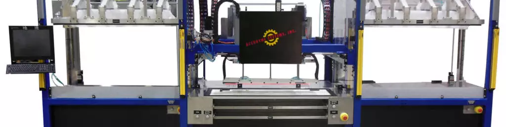
The pick/place/form/compact work cell is designed for the layup of a variety of stick-shaped constant cross-section parts (C, T, Z, L, etc.). The system also can be adapted to accommodate longer or larger components if required. The machine incorporates a pick-and-place head, twin forming heads, two debulk stations, and a two-position tool shuttle that facilitates the layup of two parts simultaneously. The work cell is equipped with tool positioning, work order and recipe management and MIS integration, but instead of laser projection to position the plies, the equipment has reference edges that form an X,Y datum for manually aligning the plies for the pick and place function. Ply backing accountability can be integrated into the cell if desired.
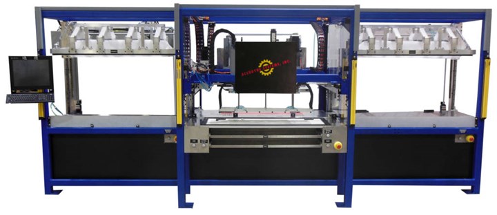
The pick/place/form/compact work cell incorporates a pick and place head, twin forming heads, two debulk stations, and a two-position tool shuttle facilitating the layup of two parts simultaneously. The work cell is equipped with tool positioning, work order and recipe management and MIS integration, but instead of laser projection to position the plies, the equipment has reference edges that form an X,Y datum for manually aligning the plies for the pick and place function. Source | Accudyne
The multi-axis work cell provides the highest level of automation, with complete integration of all five key Automation-Assisted Work Cell elements within a space-efficient footprint. The cell features ergonomics-enhancing, three-axis tool positioning (a linear vertical axis and two rotary axes) that can be adjusted for each operator.
Stringer former and trim cell
Accudyne Systems designed and built a stringer former and trim cell currently used to manufacture omega-shaped stringers for a customer in the aerospace industry. The cell can accommodate parts up to 20 feet long as well as a variety of similar shapes with laminate thickness up to 0.25 inch. The process to make the parts illustrates the functions of the work cell features, as well as how a customer can customize the equipment to meet production and price point requirements.
Similar to other work cells that Accudyne has built, the stringer former and trim cell accommodates two tools to facilitate the manufacture of two composite parts simultaneously. Prior to production, the equipment’s two laser projectors are calibrated to both of the servomotor-driven platen positions. During this procedure, the LASERGUIDE projectors (from Aligned Vision) identify and locate multiple targets on the tool platen. These points are used to establish the frame of reference between the laser projectors and the tool during production.
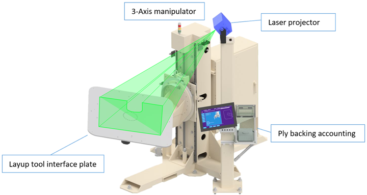
Multi-axis work cell. Source | Accudyne
The operator is supplied a pre-cut ply kit comprising composite prepreg materials at the prep workstation. A control panel prompts the operator — as part of the work order and recipe management tool — to enter the work order number, then proceeds through a number of validation steps, to ensure the work order, recipe and tool are all correctly matched. Once validated, the operator selects the approved recipe and the screen displays instructions for the sequence of operations required to complete the layup of the composite part(s). The recipe and associated data are not stored locally, but on a manufacturing information system (MIS) that ensures data integrity and version control.
Accudyne’s work cells can be supplied with multiple motion axes to facilitate ergonomic tool positioning to reduce operator fatigue. However, the tool positioning in the stringer former and trim cell consists of just one axis per tool platen; for example, lateral motion within the same plane. Once the tool is positioned, the laser projector illuminates the perimeter of the first ply on the tool. The laser projector can also be programmed to display ply number or orientation of the fabric directly onto the tool.
After placing and positioning the ply on the tool, the operator steps out of the prep area, presses the “ready” button and the tool is moved laterally, via servomotor, into the automated forming section of the work cell. The ply is formed over the tool geometry and then the tool is moved back to the prep area for operator inspection. With inspection complete, the operator steps out of the prep area and the tool is moved into an automated compaction section of the work cell, which is equipped with a permanent compaction bladder. The tool is positioned under the bladder and the frame is lowered down to the surface of the tool until a vacuum-tight seal is achieved. A vacuum is drawn under the bladder, providing evacuation of the entire bladder in 10-15 seconds via a vacuum reservoir system attached to the machine frame. The controller monitors the compaction process and can be programmed to provide various compaction cycle parameters depending on component recipe.
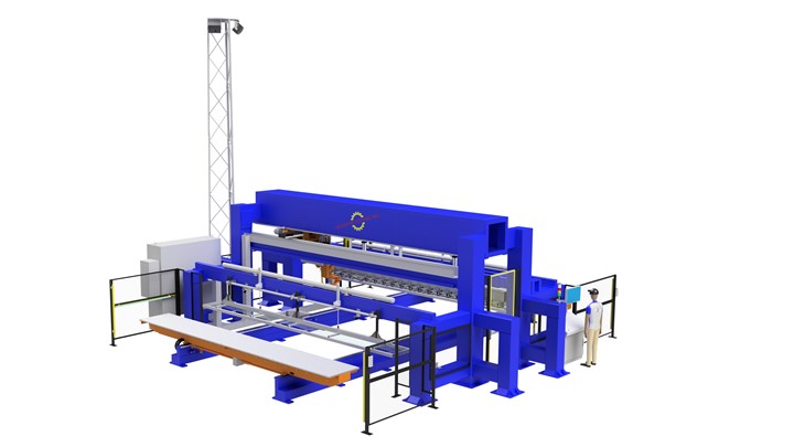
This stringer former and trim cell is currently being used by an aerospace company to manufacture an omega-shaped stringer up to 20 feet long with a laminate thickness up to 0.25 in. Source | Accudyne
While one component is being formed, compacted and/or trimmed, the operator can make progress on a second component. Layup and compaction steps continue until the component recipe has been completed. The operator selects the “Trim Cycle” mode and a bespoke six-axis CNC ultrasonic trim head, supported by an overhead box-frame gantry, trims the perimeter of the part at a rate of about 1 inch per second. The ultrasonic knife edge trims the part to an aerospace-grade tolerance. After the trim cycle is complete, the component is inspected, removed from the forming tool and placed on another tool for subsequent manufacturing operations.
Zweidler says equipment integration with a client’s MIS allows multiple Automation-Assisted Work Cells to draw from the same recipe data stored on a controlled, secure network. This digital architecture provides the ability to protect and control versioning of recipes, software, laser projection geometry, G code, etc., as well as the capability to monitor progress of a component’s build and adjust upstream and downstream activities in real time. MIS integration also can facilitate remote service access for new equipment features or software code changes.
The laser projectors in the automation-assisted work cells are integrated into the process workflow and controls through a software developers kit (SDK) provided by Aligned Vision and integrated into the cell by Accudyne. Zweidler says one of the key benefits of the SDK is that it provides access to advanced laser projection system features such as communicating servo axis positions as a common coordinate system frame of reference. This coordinate system is maintained throughout the part manufacturing process in a way that is transparent to the operator. Whenever the tool is repositioned in 3D space, the controller communicates the new tool position to the laser projector. The laser projector uses matrix geometry transforms to recalculate and correct the projection geometry for the new frame of reference. “The SDK tool is worth its weight in gold to us and the customer in terms of efficiency,” Zweidler says, noting that without it the operator might have to re-calibrate the targets every time the tool is moved, even if slightly.
Aligned Vision has also developed new technologies that, though not yet used in one of Accudyne's work cells, could, according to Zweidler, be readily adopted into a work cell with the current software. The first, LASERVISION, incorporates a camera and laser in one enclosure. The high-resolution camera operates in the same frame of reference as the laser and is used to inspect for ply orientation, ply position, foreign object debris, etc. The second technology, TARGETGUIDE, enables the owners of older equipment, without the integrated coordinate system features described above, to realize auto-target scanning following the repositioning of tooling.


Related Content

MFFD longitudinal seams welded, world's largest CFRTP fuselage successfully completed
Fraunhofer IFAM and partners have completed left and right welds connecting the upper and lower fuselage halves and sent the 8×4-meter full-scale section to ZAL for integration with a cabin crown module and testing.
Read More
Automated robotic NDT enhances capabilities for composites
Kineco Kaman Composites India uses a bespoke Fill Accubot ultrasonic testing system to boost inspection efficiency and productivity.
Read More
Plant tour: Airbus, Illescas, Spain
Airbus’ Illescas facility, featuring highly automated composites processes for the A350 lower wing cover and one-piece Section 19 fuselage barrels, works toward production ramp-ups and next-generation aircraft.
Read More
Otto Aviation launches Phantom 3500 business jet with all-composite airframe from Leonardo
Promising 60% less fuel burn and 90% less emissions using SAF, the super-laminar flow design with windowless fuselage will be built using RTM in Florida facility with certification slated for 2030.
Read MoreRead Next

Composite trends gaining industrial traction for 2026
Startups & Investors topics over the last year show the industry is rapidly gaining maturity while benefiting from macro-trends in circularity, AI and TPC and high-rate manufacturing, all potential gains for investors.
Read More
From PMCs to sandwich composites: Tracing the path of test method standardization
Over the decades, progression of PMC and sandwich composite test method development and standardization has been shaped by the requirements of the composites industry.
Read More
Cutting engine weight via thermoplastic composite guide vanes
Greene Tweed replaces metal stator vanes with its DLF material co-molded with a metal leading edge that meets performance, cost and high-rate production targets while cutting 4 kg per engine.
Read More