
Skeleton design enables more competitive composite autostructures
New approach combines thermoplastic pultrusions with injection overmolding in a two-step, 75-second process.

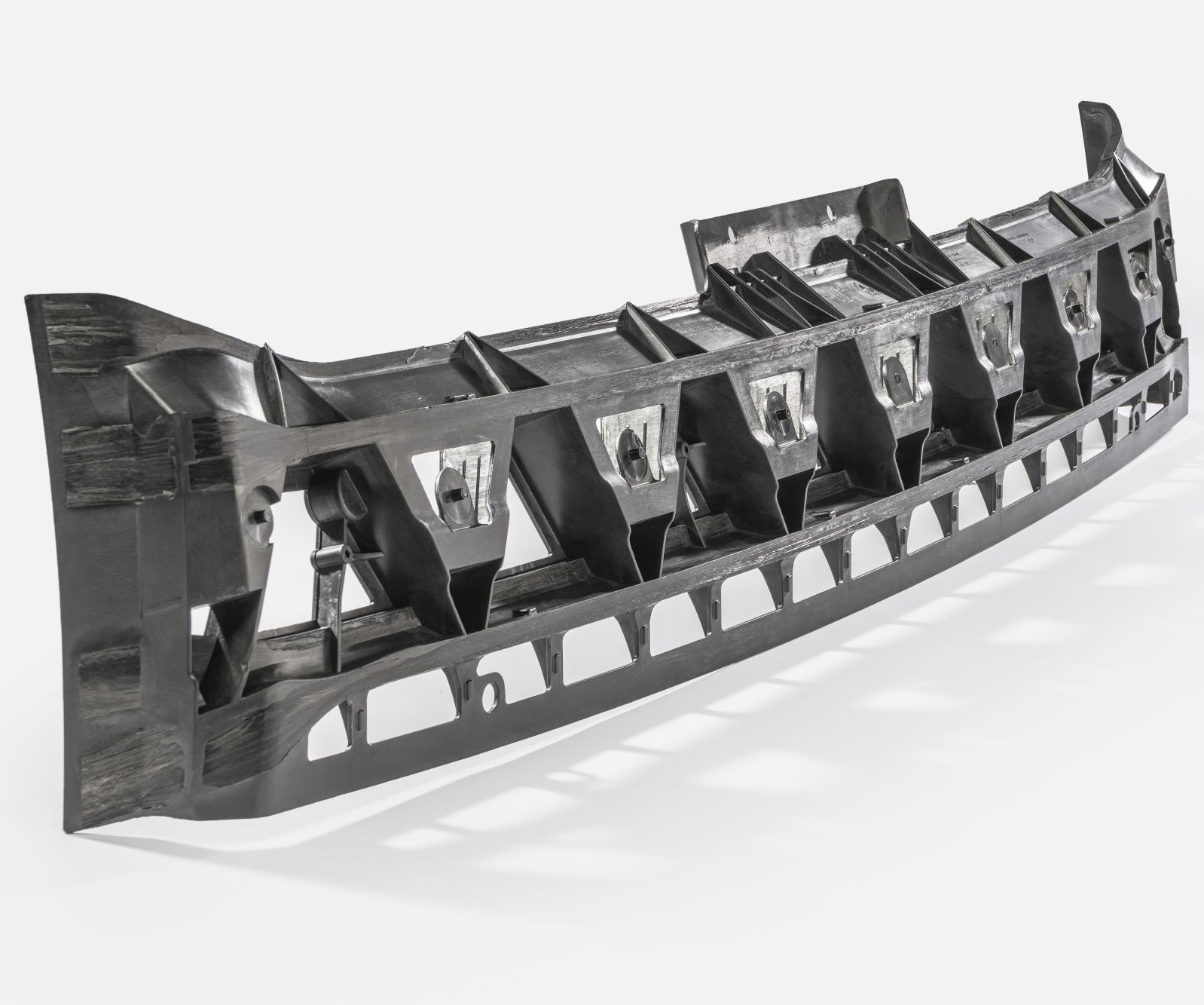
Pultruded skeleton
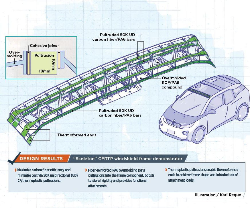
Pultruded profiles serve as the load-carrying skeleton for the overmolded, fiber-reinforced PA6 muscle of this next-generation windshield frame that outperforms the current BMW i3 structure.
Source | SGL Carbon
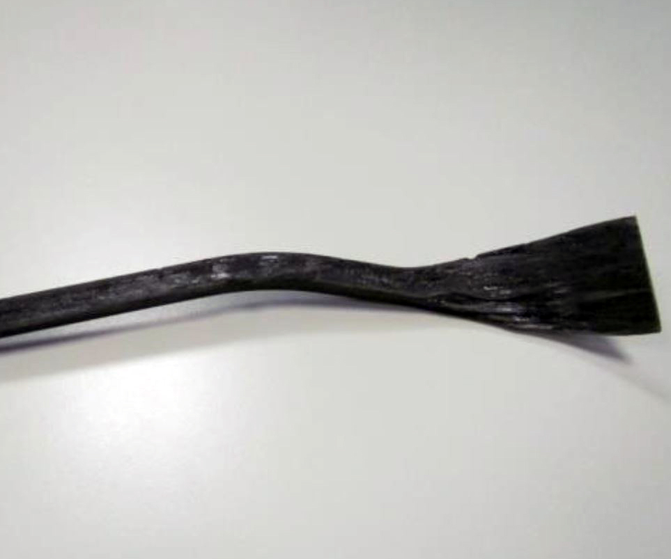
Fig. 1 Thermoformed ends
The ends of the pultruded bars in the MAI Skelett windshield frame were thermoformed to meet component shape and load introduction requirements.
Source | MAI Skelett final report, BMW Group
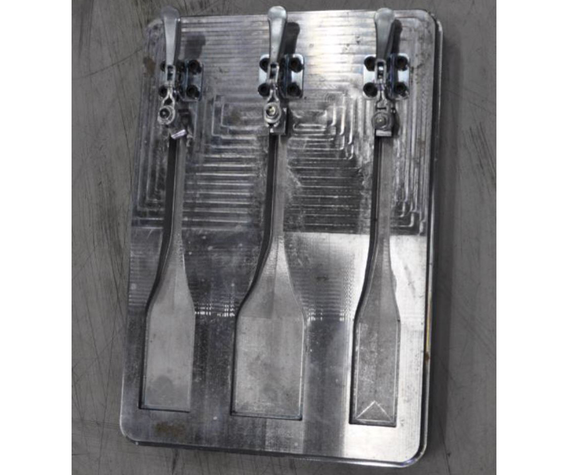
Fig. 1 Thermoformed ends
Three different shapes were trialed for thermoforming the ends of the pultruded bars. Those stretched in the direction of the matrix flow maintained the best fiber alignment to meet load requirements.
Source | MAI Skelett final report, BMW Group
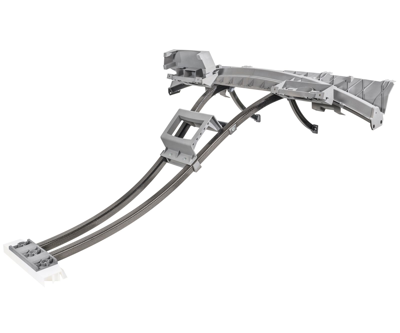
Fig. 2 Carbon carrier
Using the skeleton design approach, this 2017 alternative design for an electric vehicle instrument panel would replace thermoformed organosheet with pultrusions for the main load-carrying members with overmolding to achieve the functional attachments and dashboard design, improving efficiency and cost.
Source | SGL Carbon
Share
Read Next


As manufacturers seek to reduce the cost of composite components, designers strive to use constituent materials as efficiently as possible while enabling automated production and integration of multiple functions. For automotive applications, this challenge is exacerbated by the need for cycle times as short as 1-2 minutes.
Overmolding — injection molding thermoplastic composite features on top of continuous fiber preforms — has been pursued as a possible solution for years. For example, the CAMISMA project demonstrated an overmolded composite seat back in 2014 (see “CAMISMA’s car seat back: Hybrid composite for high volume”). “But this approach has been taken to the next level, now achieving fully automated production of thermoplastic composite BIW [body-in-white] structures,” explains Dr. Christoph Ebel, head of SGL Carbon’s (Wiesbaden, Germany) Lightweight & Application Center (LAC, Meitingen, Germany).


This advancement is thanks to a “skeleton” design approach that has been in development for several years. As first demonstrated in the MAI Skelett project in 2015, the process involves use of unidirectional (UD) carbon fiber thermoplastic pultrusions that are thermoformed and overmolded in a two-step, 75-second process to produce a structural roof member that exceeds all previous version requirements. It also integrates clips for attachments and changes crash behavior from brittle to ductile failure mode for increased BIW residual strength (see “More details on MAI Skelett design process”).
MAI Skelett demonstrator
The 17-month MAI Skelett project was supported by the German Federal Ministry of Education and Research (BMBF) and completed by MAI Carbon, a regional division of the Carbon Composites e.V. (Augsburg) network. Led by BMW (Munich, Germany), the project’s focus was to realize a specific demonstrator: the windshield frame, located between the two A pillars above the glass windscreen. Its design was based on the current BMW i3 structure, including all functional and space requirements. The windshield frame serves not only as a transverse structural member for the roof, but also provides other functions: rigidity, which also reduces noise, vibration and harshness (NVH); strength (roof pressing test) to help meet crash requirements; a fixture for interior components (for example, visor, interior trim, wiring harness for lighting, etc.), as well as support for connections with the windshield, sun roof and exterior roof panel.
The skeleton design windshield frame comprised four UD fiber-reinforced pultruded bars in the corners of the part, encapsulated in an overmolded frame to provide torsional rigidity and complex-shaped functional attachments. The pultruded profiles are not all in one plane, but instead are arranged at different heights: two are near the bottom of the 60-millimeter-tall part, and two are near the top.
Pultrusions as part of TP toolbox
For the MAI Skelett windshield frame, a 10-by-10-millimeter square cross section was finalized for the design. The goal was to use less expensive, heavy-tow carbon fibers. However, the 50K tow fiber chosen has a tight packing of myriad filaments that makes resin impregnation more difficult. “In general, this challenge can be overcome by optimized fiber guidance and spreading to reach optimum impregnation and high fiber volume content around 50 percent by volume,” says SGL product manager for thermoplastics Veronika Bühler. SGL has mastered this technology and now offers pultrusions as part of its thermoplastic toolbox. “We already had a broad knowledge of semi-finished products because of our thermoplastic tapes, which are also pultrusion-based. So we were able to quickly adapt our currently used pultrusion technologies to create our own profiles.” The process includes quality tests for fiber volume, porosity and dimensional accuracy. “The latter is very important due to automation and robot handling,” she continues. “There can be no curvature, for example, due to residual stress in the pultruded profiles.”
Beyond pultrusion reinforcements, thermoplastic resins were also investigated in MAI Skelett. Various types of polyamide 6 (PA6 or nylon 6) were tested to determine the required viscosity and rheology for optimized pultrusion quality and speed. SGL offered a range of materials for the project via its thermoplastic toolbox, which comprises UD tapes, organosheets, chopped fiber for short and long fiber-reinforced compounds, and now UD-reinforced pultrusions, all based on SIGRAFIL 50K carbon fibers with sizing suitable for a matrix of polypropylene (PP) and polyamides, including PA6 or in-situ PA6. “It is essential to harmonize fibers, sizing and matrix in order to achieve optimum performance of composite structures,” says Bühler.
She also explains in-situ PA6: “This is when you react caprolactam monomers, or a single monomer with a catalyst and an activator, which then polymerize [form long polymer chains] during molding of the composite part.” In other words, the caprolactam polymerizes in situ into a polyamide. Bühler notes that polyamides as a polymer group include PA66 and PA12, as well as certain types of PPA as additional matrix choices.
Another important aspect of the windshield frame’s manufacture is the ability of thermoplastic semi-finished products to be thermoformed during and after molding. This enables further functionalization of the shape as well as fusion bonding during overmolding. Both were important factors in the MAI Skelett demonstrator design.
Thermoforming and overmolding
Production of the MAI Skelett windshield frame began with carbon fiber/PA6 pultruded profiles. These then had to be modified to accommodate the shape of the component as well as load introduction at different points. Thermoforming was chosen to do this, with the primary concern that the high strength and stiffness of the carbon fiber could only be realized by keeping it as straight as possible. This was achieved when the pultruded bars were stretched in the direction of matrix flow, and then flattened and bent at the ends of the bars (Fig. 1).
The second step of the process was to place the thermoformed pultruded profiles under an infrared heater to bring them up to temperature in less than 50 seconds, followed by transfer into an injection mold using an automated handling system developed for the purpose. All parts within the project were produced on existing injection molding machines. Fiber-reinforced compound was then overmolded onto and around the profiles. Precision was required in both the mold and the process during overmolding in order to hold the four thermoformed, pultruded bars in position.
The total cycle time for the two-step process (thermoforming and overmolding of premade pultrusions) was roughly 75 seconds. “Because the thermoplastic matrix is remelted prior to overmolding, it allows for forming and bonding the premade and thermoformed bars into the finished part in very short cycle times,” Ebel explains. “Generally, the fusibility of thermoplastics also enables joining with even metallic components,” adds Bühler, noting that thermoplastic thermoforming and injection molding processes offer excellent reproducibility and process control, which are critical factors for high-volume production.
Ductile failure
PPA and PA6 profiles with compatible molding compounds using glass and carbon fiber were evaluated to explore a more ductile failure mode for the component. Although a more ductile failure mode decreased the amount of load the windshield frame could transfer, it improved the structural integrity of the BIW as a whole.
Analysis methods included solid modeling, rebar modeling (geometry modeling where the pultrusions act as rebar reinforcing the overmolding) and modeling using shell elements, as well as various combinations of these. Software included the FE solver ABAQUS (Dassault Systèmes, Paris, France) and Dakota parameter solver developed by Sandia National Laboratories (Albuquerque, N.M., U.S.). OptiStruct (Altair Engineering, Troy, Mich., U.S.) was used for topology optimization.
Although BMW did not specify a preferred material combination in its final project report, it did conclude that final simulation and test results showed that the skeleton components exceeded all requirements for the current carbon fiber-reinforced plastic (CFRP) part except for torsional stiffness, which was determined not to be a key design driver for the windshield frame. The skeleton design exceeded both load level and energy absorption in crash load cases vs. the current CFRP part. It also succeeded in achieving a more ductile failure mode, which further advances not only composite structure crash performance but also the understanding of that crash performance and how it relates to the BIW structure as a whole.
Future skeleton design applications
In the MAI Skelett final report, BMW noted that it had identified six other vehicle components that could benefit from the significant reduction in manufacturing, material and tooling costs provided by using the skeleton design approach. SGL Carbon suggests applications in both automotive and aerospace seat structures, dashboards, robot arms, X-ray benches and more.
However, the skeleton design approach was developed even further, extending to multiaxially stressed components in the follow-on project MAI Multiskelett (which was conducted from September 2015 to June 2017). It looked at areas where bearing components and pultruded profiles intersect, and also at high-load introduction areas, particularly for large structural components where several main load paths cross. As in the previous Skelett project, component designs and cost-efficient serial production lines were investigated.
An example of how skeleton design can further optimize existing composite components is the Carbon Carrier front interior for an electric vehicle (Fig. 2) developed by SGL and automotive technology specialist Bertrandt (Ehningen, Germany) in 2017. Integrating all major function and trim components of a conventional instrument panel, the Carbon Carrier was based on a thermoformed organosheet as the load-bearing “backbone” to add stiffness. “In the future, this part could be replaced by a design with overmolded thermoplastic profiles,” says Ebel. “This would omit cutting, layup and trimming operations for the organosheet. Also, the cross member would be obsolete because we would integrate it as pultruded profiles and overmold them to achieve the dashboard design. This overmolded part would also provide more space and flexibility to accommodate the required attached elements as well as screws and clips for attaching these elements or cables, etc.”
Ebel concedes this would be a huge design change, “but it reduces cost and makes the whole component more efficient.” He points out that it is possible to design a process with almost no waste no waste because profiles are cut exactly to length as needed and no carbon fiber reinforcement is lost in these steps or in the thermoforming prior to overmolding. Bühler points out that seats are also prime candidates for skeleton design. “In composites, they are typically made with fabrics or tapes, and are still sheet-like structures. But we could decrease thickness in the plane area by integrating profiles at the bottom and increasing stiffness.” She notes that pultruded profiles are not the only efficient UD product possible to build around. “It could also be tape, which is easily adapted to the load paths for each part.”
“We are touring a lot of companies at the Lightweight & Application Center,” says Ebel. “The skeleton design as an additional innovative concept has inspired a lot of interest and is seen to be very promising by our visitors.” He explains that the center has built up its design capabilities and can help companies integrate innovative ideas such as the skeleton concept to open up a new design space for future material-efficient components.
“There are a lot of applications where we can use designs similar to the windshield frame,” says Bühler. “It is important for the industry to advance from quasi-isotropic layup, which leaves much of carbon fiber’s strength and stiffness on the table. Instead, we must exploit more efficient material forms, putting each material only where it is needed. This is what the industry needs for the future.”


Related Content

Donghua University demonstrates in situ consolidation of thick low-melt PAEK laminates
SNAPSHOT: Even without using heated tooling, the Center for Civil Aviation Composites achieved thermoplastic composite laminates with <1% voids, near-zero warpage and good consolidation, showing potential for OOA production.
Read More
AM method enables tool-free, energy-efficient thermoset composites production
University researchers highlight how the combination of a thermally curable resin system with photothermal curing eliminates the post-curing steps involved in discontinuous, continuous fiber parts fabrication.
Read More
Clean Aviation's regional aircraft technology testbed #2 demonstrates advances with composites
European project advances OOA outer wing box using resin infusion and thermoplastic composite technologies.
Read More
Induction heating system enables OOA composites processing
JEC World 2025: Roctool focuses attendees’ attention on the light induction tooling (LIT) system targeting efficiency, sustainability and performance.
Read MoreRead Next

Sentherm conductive polymers match aluminum thermal performance, cut weight
Tailored filler networks, anisotropic material design and manufacturing process control achieve hybrid polymers for EVs, batteries and other automotive-related electronics with 95% of aluminum’s thermal performance and 25-45% reduced component weight.
Read More
Kaneka BMI material attains >25% lead time, >20% tool cost reductions in Janicki evaluations
Process evaluations find that novel BMI polymer chemistry addresses longstanding manufacturing challenges of BMI tooling prepregs while maintaining high temperature performance and durability.
Read More
Polestar 5 takes aesthetics and circularity approach to biocomposite seatback design
The 2026 Polestar 5 expands the company’s use of sustainable materials design in the interior, including flax fiber/thermoplastic seatbacks that save 7 kilograms of weight and reduce overall plastics use.
Read More