
Thermoplastic composites: Primary structure?
Yes, advanced forms are in development, but has the technology progressed enough to make the business case?

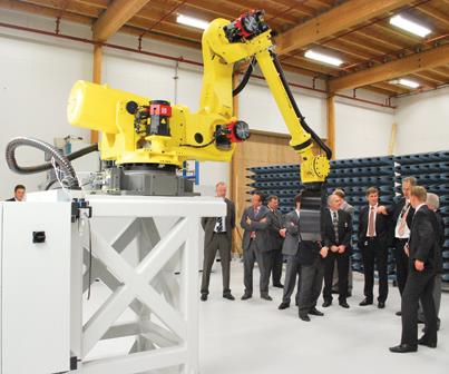
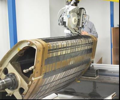
Fokker Aerostructures (Hoogeveen, The Netherlands) executives view the company’s recently developed automated placement system for C-PEKK tapes. Its Fanuc robotic arm is fitted with an ultrasonic welding head. It is a more flexible and less costly solution than gantry-style machines. Source: Fokker Aerostructures
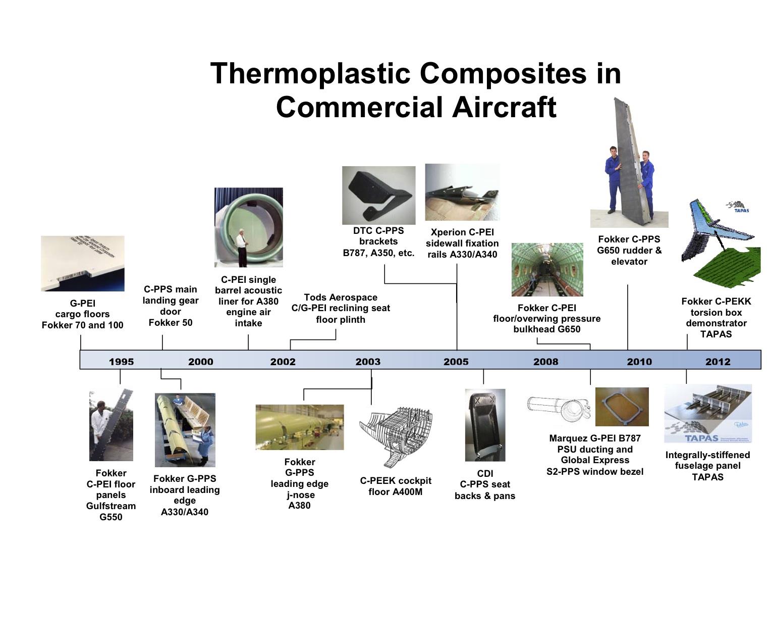
Thermoplastic Composites in Commercial Aircraft: A Timeline
Fokker’s 12m/39-ft span carbon fiber-PEKK torsion box demonstrator for TAPAS features integrated T-stiffeners. The revolutionary butt-joints in the stiffeners show a 10x increase in peel strength and a 2.5x higher joint failure threshold. Source: Fokker Aerostructures
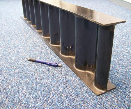
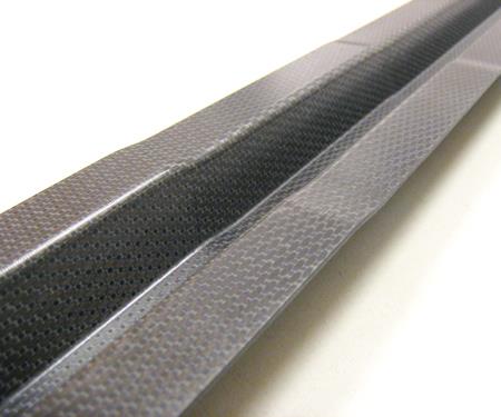
Fokker’s development of its butt-joint system has enabled new designs not easily formed in thermoset composites, such as the sine-wave beam pictured here. Source: Fokker Aerostructures
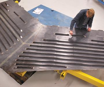
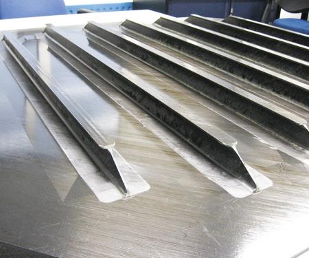
TPC ribs from flat plate stock and radius inserts for Fokker’s COALESCE leading edge are placed into cavities on this tool. A robotic arm then places TPC tape on top, forming two leading edges to be coconsolidated in a short autoclave cycle. Source: Fokker Aerostructures
Fokker’s butt-jointed T-stiffeners enable TPC primary structures that cost 15 to 30 percent less than carbon fiber/epoxy. Source: Fokker Aerostructures
Dutch Thermoplastic Composites (Almere, The Netherlands) has developed press-formed TPC stringers with variable thickness and complex geometry for the TAPAS fuselage demonstrator, with a total cycle time of 15 minutes, starting from CNC materials cutting. Source: Dutch Thermoplastic Composites
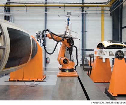
A Flash TP automated placement machine from Coriolus Composites (Quéven, France) forms a carbon/TPC Airbus A30X lower fuselage skin demonstrator. Source: Airbus; Photographer: S. Bonniol


Over the past 25 years, thermoplastic composites (TPCs) have increasingly earned their way onto commercial and military aircraft. They’ve done so through the efforts of a few pioneering companies that have developed materials and processes, enabling continuous fiber reinforcement of advanced matrices such as polyphenylene sulfide (PPS), polyetherimide (PEI), polyetheretherketone (PEEK) and polyetherketoneketone (PEKK).
Given the excellent fire, smoke and toxicity (FST) performance and cycle times of minutes vs. hours for thermosets, the influx of TPCs into aircraft interiors was no surprise. Ten Cate Advanced Composites (Nijverdal, The Netherlands), for example, claimed in 2006 as many as 1,500 separate part numbers on Airbus aircraft, made from its Cetex PEI and PPS sheet products. But TPCs didn’t stall there. Adoptions have progressed with each new aircraft (see the “Thermoplastic composites in commercial aircraft” timeline at right). Leading TPC manufacturers confirm that they are working on developments for both The Boeing Co.’s (Seattle, Wash.) 787 and the A350 XWB from Airbus (Toulouse, France). Although few details are available for TPC production on these aircraft (see “TPCs on B787 and A350,” under "Editor's Picks," at right), Airbus and others have made no secret of the fact that they have set their sights very high. Airbus, through the Thermoplastic Affordable Primary Aircraft Structure (TAPAS) consortium, intends to demonstrate a TPC torsion box, such as that used in horizontal tails, featuring induction welded butt-joint stiffening ribs. Also in process is a TPC fuselage panel with integrated stiffeners. Meanwhile, the Consortium for Research and Innovation in Aerospace in Québec (CRIAQ, Montréal, Canada) continues its development of a thin-walled, tapered-cylinder TPC helicopter tail boom with welded internal stiffeners.


Fokker leads TAPAS torsion box
TAPAS includes Airbus and eight thermoplastic composites specialists based in The Netherlands — Fokker Aerostructures (Hoogeveen), Ten Cate, Airborne Composites (The Hague), KVE Composites Group (The Hague), Dutch Thermoplastic Composites (Almere), Technobis Fibre Technologies (Uitgeest), Technical University Delft, University of Twente, and the Dutch National Aerospace Laboratory (Amsterdam). The collaborators intend to develop the technology necessary to produce large thermoplastic composite primary aircraft structures. The goal of this four-year program, started in 2009, is to expedite a technology readiness (TRL) level of 6, culminating with two large-scale demonstrator components. (TRL 6 stands for Technology Demonstration on a scale from TRL 1 – Basic Technology Research to TRL 9 – Systems Test, Launch & Operations.) One will be a 12m/39-ft span torsion box and the other, a 4m/13-ft long, double-curvature fuselage panel. The program is intended to position participating partners for new programs like the A30X (next-generation A320).
The TAPAS torsion box demonstrator is basically a redesign of Gulfstream Aerospace Corp.’s (Savannah, Ga.) Gulfstream G650 horizontal stabilizer, previously a carbon fiber/epoxy hat-stiffened skin construction. The torsion box is the fixed structure of the tail, and it is more heavily loaded than the movable rudder and elevators, which Fokker now produces in carbon/PPS, achieving a 10 percent weight reduction and a 20 percent cost savings vs. previous carbon/epoxy. In fact, Fokker along with Gulfstream, KVE, TenCate Advanced Composites and Ticona (Amesbury, Mass.) won the 2010 JEC innovation award in Aeronautics for developing these first TPC primary structures and the first industrialized induction welding method (contributed by KVE). “We wanted to look at a torsion box, as a basis for control surfaces, wings and complete tails to be made from thermoplastic composites in the future,” says Arnt Offringa, R&D director for Fokker Aerostructures. “With the G650 products, we already had the tooling, test rigs and material data required.” The selected 12m span represents a horizontal flap for an airliner or half the span of a business jet horizontal tail. Only the 6m/20-ft middle section of the demonstrator is thermoplastic (Fokker uses already built thermoset left and right tips) but is more complex than the G650 components, and an important step forward. In fact, Fokker already has developed a TRL 4 (Technology Development level) subcomponent TPC demonstrator that measures 0.5m by 1m (1.6 ft by 3.3 ft), with three integrated stiffeners. The part has undergone static and fatigue testing in all conditions. Production and testing of the larger demonstrator will be completed by the end of 2011.
The torsion box features tailored skins with varying thickness, from 2 mm/0.08 inch at its thinnest to 8 mm/0.4 inch at the root, and will be made from unidirectional carbon fiber/PEKK. The integrated, butt-jointed T-stiffeners are revolutionary in terms of manufacturing process, cost and weight. “We were looking for a low-cost way of adding vertical stiffeners to I-shaped floor beams a few years ago,” Offringa recalls. “Instead of using laminates with flanges, we tried a simple flat plate, butt jointed to the I-beam during consolidation.” (See “Reinforced thermoplastics in aircraft primary structure," under "Editor's Picks," at top right). The butt joint was an order of magnitude stronger than previous welded joints, which Fokker had developed for A340 and A380 J-nose leading edge structures. “The peel strength of a welded joint is roughly 10 N/mm (57 lb/inch) independent of thickness, while the butt-jointed stringer is ten times stronger,” Offringa maintains, emphasizing that at failure, “the plies of the underlying skin pull apart vs. a bond rupture.” Fokker then enhanced bond strength with a pair of injection molded radius inserts that help transition load from the perpendicular stiffener to the skin. The short carbon fiber-reinforced PEKK inserts widen the joint area to three times the stringer thickness. They exhibit strength only one-third less than that of the composite laminate, “We tried continuous unidirectional fibers,” Offringa notes, “but the short fiber/PEKK combination worked best to reduce stress in the joints.”
Simple flat preforms are made using automated tape placement (ATP) and then waterjet cut to supply the two pieces for each T-stiffener. Stiffener components and radius inserts are placed into tool cavities designed to receive them. Tooling blocks are positioned, which locate the components precisely and, during molding, apply pressure. The thermoplastic composite skin is then tape layed on top using an off-the-shelf robotic arm made by Fanuc (Oshino-mura, Japan), and specified and programmed by Boikon (Leek, The Netherlands), instead of a gantry type ATL/AFP machine. After caul plates and a vacuum bag are applied, the assembly is consolidated during a three-hour autoclave cycle. The goal is to transition, eventually, to using only vacuum and a heated tool.
The decision to use a robotic arm was based on cost: roughly $100,000 for industrial robots vs. $1 million for large ATL/AFP machines. Offringa notes that Coriolis Composites SAS (Quéven, France), Accudyne Systems Inc. (Newark, Del.) and Automated Dynamics (Schenectady, N.Y.) have all looked into using robots instead of gantry-style equipment. “For thermoplastic composites, you do not need large forces to tack the material together, Offringa contends. “Heat is enough.”
Although the large ATL/AFP machines typically use gas or laser heating systems, Fokker chose low-cost ultrasonic welding, a process with which it has many years of experience on the J-nose leading edges. Fokker uses Vericut software by CGTech (Irvine, Calif.) to translate CATIA (Dassault Systèmes, Paris, France) CAD data into something the robot can build. This system is expected to enable affordable growth. “For small volumes of limited-size products — for example, an 80-cm by 300-cm (32-inch by 118-inch) business-jet flap — a single robotic cell will work, and increased volumes can be accommodated by adding robots,” Offringa explains. “Larger structures, like aircraft tails or fuselage panels, can be achieved with multiple synchronized robots, each capable of several material widths.”
Using automated layup drove the choice of PEKK as a matrix. In automated layup, unidirectional tapes are easier to use than fabrics. Moreover, carbon/PEKK tapes are readily available from Cytec Engineered Materials (Tempe, Ariz.). Ten Cate is working on a new product as well.
Sine-wave beams and A30X leading edges
Fokker’s butt-joint system has enabled a faster, more cost-effective way of producing sine-wave beams, which are not easily formed in thermoset composites. Fokker began with the beam’s web, a carbon/PEKK flat plate, press-formed in the shape of a sine wave. To expedite R&D, two sine wave-shaped radius inserts were roughed out by making a tool with a sine wave groove and then press forming heated chopped carbon/PEKK material pellets into it. Nevertheless, the rough part showed no voids, indicating that injection molding could be used without trouble for insert production. The beam’s flanges were cut from preformed carbon/PEKK flat laminate. Then the web, inserts and flanges were placed in a tool, bagged and coconsolidated, producing a structure with a much higher stiffness and buckling-resistance than a simple I-beam.
The butt-joint method also enabled production of a skin/stringer design that features multiple flat ribs, now employed in the 3.5-year, $6 million Level 1 COALESCE (Cost Efficient Advanced Leading Edge Structure) project within the European Union 7th Framework program. By mandate, the Airbus A30X must cost less per kilogram than the latest wide-body platforms. Accordingly, says Offringa, its leading edge must cost less than Fokker’s welded-rib leading edge on the A380 (see “Thermoplastic composites gain leading edge on the A380,” inder "Editor's Picks"). Offringa recounts the design’s origins: “We asked ‘How can we get rid of welding? Maybe if we make the ribs very small and fuse them to the skin all in one shot?’” The ribs are waterjet cut from large preformed flat plate stock into tailored shapes to minimize material. Radius inserts are injection molded and the skin is robotically fiber placed. Then, the assembly is coconsolidated to produce a structure that costs 30 percent less than the A380 leading edge, based on cross-section analysis (i.e., regardless of part length).
Developing complex fuselage stringers
Dutch Thermoplastic Composites (DTC) also is pursuing new TPC stringer designs as it explores press-formed structures with variable thickness and complex geometry for the TAPAS fuselage demonstrator. DTC has made lightly loaded, constant-thickness TPC ribs in the past, similar to those in Fokker’s A340 leading edge. But, says DTC’s CEO David Manten, “When you go to more highly loaded structures, like fuselage panels, ribs are often made of aluminum because of the many formed details and thickness variations used to achieve higher strength and stiffness with less material. In thermoset composites, ply build-ups and drop-offs are used to achieve the same result, but thermoplastic composites enable much more complex geometry in a very fast cycle time.”
DTC built a custom press capable of forming 1-ft by 1-ft (0.3m by 0.3m) carbon/PPS or carbon/PEKK profiles up to 3m/10 ft in length. The profiles can be formed within a 5- to 10- minute cycle time, and they are compatible for co-consolidation with the demonstrator fuselage panel skin. Development began with single-ply laminates and now has progressed to a 2-mm/0.080-inch thick quasi-isotropic layup. Manten describes the process: “We build up the plates ourselves and then pre-consolidate them using vacuum to extract air before press forming, routinely achieving porosity levels way below 2 percent.” DTC can press three stringers simultaneously, each up to 8 inches (203 mm) in width, and the press is capable of more than 400˚C/752˚F with automated material transport. The thickness in the stringers varies between 0.125 inch and 0.250 inch (2.48 mm and 5.50 mm). DTC is developing a robotic system to automate flat blank production. Currently, it can lay up a blank in three to four minutes. So the process as a whole moves quickly: CNC cutting of TPC materials, robotic layup, vacuum preconsolidation and automated transfer to forming press, for a total cycle time of 15 minutes. During the next six months, DTC will transition to a commercial-scale machine, capable of 3.5-ft by 1.5-ft (1.1m by 0.5m) blanks up to 3m/10 ft in length.
TPC helicopter tail boom
CRIAQ is a government-funded aerospace consortium of 62 Quebec-based aerospace companies, universities and government organizations, including the major OEMs Bombardier (Montréal), Bell Helicopter (Mirabel) and Pratt & Whitney Canada (Longueuil). Its mission is to develop novel concepts and processes that can be applied to future aerospace products. Among its composites projects are two devoted to TPC structures: (1) develop and validate a composite tube for a light helicopter skid landing gear and (2) demonstrate a thermoplastic tail boom for helicopters. The tail boom is typically a thin-walled, tapered cylinder that connects the cabin to the tail rotor and must endure significant bending moments as well as high-temperature engine exhaust. The CRIAQ tail-boom section is approximately 4 ft/1.2m in length with diameters representative of actual aircraft (diameters vary from 10 inches/0.3m at tail to 27 inches/0.7m at cabin junction). Because rotorcraft structures are confined by low production volumes and complex geometries, no helicopter manufacturer has yet been able to make the business case for using TPCs in production. CRIAQ’s purpose is to look at the processing parameters and latest materials and equipment in an attempt to overcome these issues.
TPC primary structure issues
According to some industry experts, thermoplastic composites still have significant barriers to overcome before they are widely used in complex, contoured primary structures, particularly for aircraft produced in smaller volumes. These include cost, automated processing speed and quality, and lack of developed repair technologies.
Because aerospace-grade thermoplastic prepregs cost more than thermoset prepregs, some observers say TPC parts cannot compete cost-wise simply by using the same automated layup and autoclave consolidation process currently used for thermoset composite primary structures. According to Dr. Ali Yousefpour, composites group leader at the Aerospace Manufacturing Technology Center, Institute for Aerospace Research, National Research Council of Canada (NRC, Montreal, Quebec), “The best approach would be in-situ consolidation, so that when you are done, you have the part with no secondary processing required. But that still needs more work to ensure 100 percent consolidation and sufficient crystallization.” Yousefpour notes that this is the only true out-of-autoclave processing, a benefit often touted for TPCs.
Most high-performance thermoplastics require temperatures between 400˚F and 800˚F (200˚C and 430˚C) to ensure fiber wet out, with a consolidation pressure of up to 200 psi (1,380 kPa) being typical. One manufacturer estimated that the high-temperature, high-pressure autoclaves and presses required for most current TPC post-consolidation cost about twice that used to process thermoset composites and, therefore, the resulting capital burden is difficult to justify for low production volumes.
Fokker’s remarkable success converting floors, post-buckled leading edges, control surfaces and tail components to TPCs has been attributed by one critic to the fact that each instance involved ruled surfaces (2-D) or moderately curved geometry and offered the opportunity to consolidate high part-count assemblies. Replacement of aluminum, therefore, was cost-justified by eliminating the time and expense of mechanical fastening. Thus, assembly has driven the cost regardless of the material, enabling welded TPCs to compete with aluminum and thermosets, where for other primary structure, it may be less attractive.
It is also argued that those who have had success have understood the physical limitations of TPC materials and addressed these constraints in their manufacturing processes. For example, ribs and spars have typically used flanges that are short or have a 2-D radius, so that the complex intersections are preformed and then welded. However, these limitations affect TPCs’ competitiveness in automated processes. “The true in-situ process is rather slow,” Yousefpour reports, noting that thermoset automated placement uses a soft compaction roller, which deforms to go around sharp corners and edges, a factor that increases both precision and speed. “TPC automated placement typically uses a hard compaction roller to sustain the higher temperatures required,” explains Yousefpour. Some companies are exploring modular or flexible compaction rollers, he points out, but slow processing remains a challenge. Traditionally, thermoplastic prepregs also have been stiffer, exacerbating the issues of steering at high speed over complex contours, and they require controlled cooling to manage crystallization of the TPC matrix. Yousefpour adds, “The most forgiving material right now is PEEK, but it is much more expensive. Other high-end thermoplastic polymers do not achieve the required crystallization with AFP, so it still must be heated under pressure.” Reportedly, typical TPC laydown rates are much less than 10 lb/hour. Carbon/epoxy materials for large commercial structures can be applied at 15 to 40 lb/hr. Lay-down rates are usually noted as a function of machine speed in m/sec, but this has limited value in describing the part cost in kg/hr because geometry, steering, in-situ placement, and processing parameters can slow machine speed and interrupt head travel. Accordingly, the overall part cycle time and cost are still an issue. Industry sources suggest that laydown rates need to be three to five times faster for PEEK and 10 to 20 times faster for PEKK to make the business case for use in large primary structures for lower-volume aircraft.
Because thermoplastic prepregs are not tacky, adhesion of the first ply to the tool during automated placement also has been an issue, especially on contoured surfaces. Airbus was awarded a patent on July 13, 2011, which proposes one solution to the problem: applying negative pressure to the layup via a porous mold. Another issue is that TPC materials are difficult to bond with nonthermoplastic materials, such as epoxy. Unitized structure has been built with various welding technologies, but to date, this has been possible only when all the welded parts are TPCs. Lack of repair strategies is also an issue. “There has been little talk about repair of TPC structures,” claims Yousefpour, “Fusion bonding may be used, but needs to be developed.” Questions must be answered: “For example, how will heat and pressure be applied for bonding and how will repairs be inspected for quality?”
Business case debate
Fokker produces aluminum and carbon fiber/epoxy horizontal stabilizers for Dassault and other OEMs, and a variety of flaps for Airbus and Boeing. Therefore, it has production and cost data for comparison with TPC technology. For the Gulfstream G650’s rudder and elevators, the company compared its own hat-stiffened carbon/epoxy construction with new TPC butt-jointed structures, produced using ATP robots and three-hour autoclave co-consolidation cycles (vs. seven to nine hours for cocured epoxies). In this case, the TPC approach reduced overall hours, resulting in a 25 percent cost reduction.
Part of this reduction comes from using less material via the butt-jointed design, an extension of post-buckled skin/stringer design originally developed by composite structures pioneer Dr. John Hart-Smith. Instead of preventing buckling — one of the main failure modes — with a thick skin, Hart-Smith’s design allows local buckling at the highest service loads, but constrains it with bonded stiffeners, reducing overall skin thickness and weight. It also makes every ounce of material work to its fullest. Butt joints take this one step farther by using an optimized welded joint instead of adhesive bonds to extend the failure load by a factor of 2.5. Both TAPAS demonstrators exploit this welded post-buckled skin/stringer design.
Fokker’s Offringa points out that although TAPAS is geared toward commercial airlines, the butt-jointed parts Fokker is developing also are aimed at business jets, which, like rotorcraft, are produced in smaller volumes. For the G650 parts, he adds, a 12m/39 ft long, 3.5m/12-ft-diameter, gas-heated autoclave capable of 400˚C/752˚F is used, which is more than enough for most thermoplastic composite materials. “It cost €2 million [$2.7 million USD], typical for this type of autoclave.” Offringa contends that an autoclave of this size should be sufficient for curing helicopter parts. High-temperature capability does add cost, but not nearly as much as that required for large-diameter parts, such as those used on the 787.
It is interesting to note that Sikorsky Aircraft (Stratford, Conn.) has pursued a large thermoplastic floor assembly for years, first with Automated Dynamics for the UH-60M Black Hawk upgrade and most recently for the CH-53K transport helicopters used by the U.S. Marine Corps, with DRS Technologies (Parsippany, N.J.) and Fiberforge (Glenwood Springs, Colo.). In the March 21 issue of The Aspen Times, Fiberforge chief operating officer David Cramer said that this project is now moving into full-scale production. “It’s the largest heavy-duty helicopter in the fleet,” Cramer said, noting that the TPC floor meets the Marines’ durability needs and cuts weight by 25 percent vs. the previous aluminum design — important to Sikorsky as it looked to reduce weight after redesigning the helicopter’s engine for greater thrust.


Related Content

Low-cost, efficient CFRP anisogrid lattice structures
CIRA uses patented parallel winding, dry fiber, silicone tooling and resin infusion to cut labor for lightweight, heavily loaded space applications.
Read More
The next evolution in AFP
Automated fiber placement develops into more compact, flexible, modular and digitized systems with multi-material and process capabilities.
Read More
Composites end markets: New space (2025)
Composite materials — with their unmatched strength-to-weight ratio, durability in extreme environments and design versatility — are at the heart of innovations in satellites, propulsion systems and lunar exploration vehicles, propelling the space economy toward a $1.8 trillion future.
Read More
Otto Aviation launches Phantom 3500 business jet with all-composite airframe from Leonardo
Promising 60% less fuel burn and 90% less emissions using SAF, the super-laminar flow design with windowless fuselage will be built using RTM in Florida facility with certification slated for 2030.
Read MoreRead Next

Reinforced thermoplastics in aircraft primary structure
Carbon/PEKK floor beams prove production worthiness of lower cost, fast coconsolidation process.
Read More
Marquez innovates aircraft TPCs
Marquez (Montréal, Québec, Canada) supplies TPC ducting for The Boeing Co.’s 787 Personal System Unit (PSU), and the TPC structural window bezel used on all Bombardier (Montréal, Canada) Global Express business aircraft.
Read More
Thermoplastic composites gain leading edge on the A380
Breakthrough manufacturing process produces lightweight, affordable glass-reinforced PPS J-nose on the worlds largest commercial aircraft wing.
Read More