
Sensors for monitoring resin infusion flow front and cure
InFactory Solutions commercializes technology to provide real-time resin impregnation and cure data across composite parts for zero-defect, intelligent process chains.


This is the promised follow-up to my blog on the ZAero project for zero defect manufacturing of aerospace composites. Here, I speak with Franz Engel, managing director for InFactory Solutions, and Christopher Buchmann, the company’s head of material & process engineering. InFactory is a spinoff from Airbus that is commercializing a variety of automated, connected and intelligent systems for composites manufacturing. It also offers data analytics and engineering consulting services. One of its first products, an inline sensor for automated fiber placement (AFP) has already been installed and qualified in an MTorres AFP machine.
Now the company is developing a sensor which can provide data in real time on where the resin flow front is during infusion of carbon fiber reinforced plastic (CFRP) and other composite parts, as well as the level of impregnation and state of cure. InFactory Solutions calls its technology Cure and Flow Front monitoring, or CFF-Monitoring


The idea started during Buchmann’s Ph.D. thesis work at Airbus Innovations (Ottobrunn, Germany). “I was looking at increasing the robustness of CFRP process chains – not technology-specific, but focusing on general approaches — in collaboration with Premium Aerotec,” he explains. This is when Buchmann identified time-domain reflectometry (TDR) as a method to monitor the resin flow front during infusion and use the same sensor to measure the cure of the resin. “We then completed a proof-of-concept study, investigating different possibilities, and were able to prove it is an effective method,” he says. “We saw its importance not only for aerospace composites but also in other industries, such as automotive and wind energy.”
The team filed a patent together with Airbus, including use of this technology to monitor the cure in an adhesive bondline as well as the homogeneity in bondline thickness. InFactory Solutions is now in the process of commercializing a TDR sensor, working with a wide range of customers to determine exactly what they need in terms of sensor format, placement and data analysis, etc.
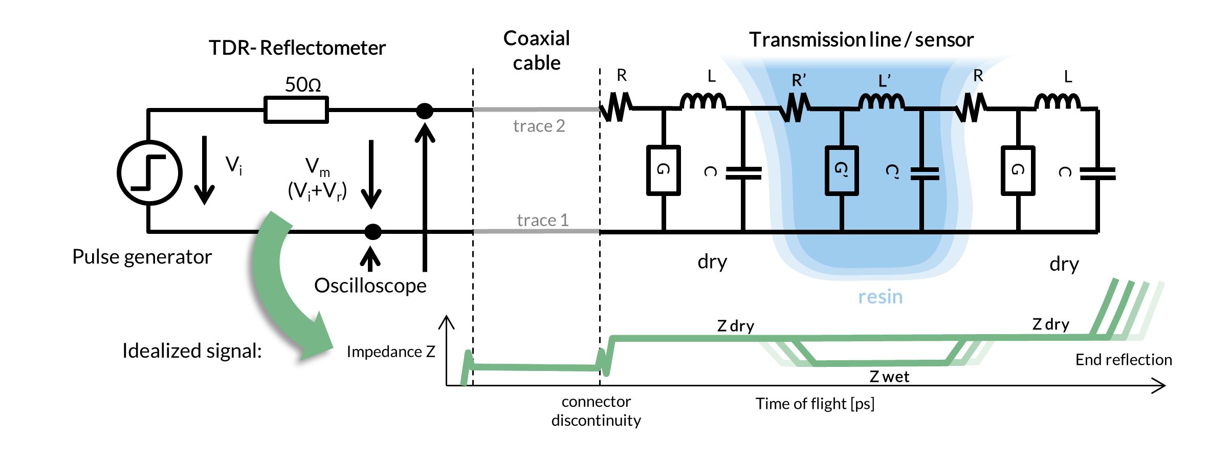
Time-domain reflectrometry (TDR) measures the reflection of voltage pulses along a conductive line sensor to provide a profile of a composite laminate’s dielectric properties, which change from dry preform to fully resin-infused to fully cured.
SOURCE: InFactory Solutions.
Time-domain reflectrometry
How does TDR work? “It is was first developed to detect defects in electrical cables,” Buchmann explains. “You send a voltage pulse into an electrical transmission line and record any reflection over time using a high-bandwidth oscilloscope.” He notes the pulse may take 2000 picoseconds (1 ps = one-trillionth or 10-12 of a second) to travel up to any defects in the cable, and then part of it is reflected. The oscilloscope measures this reflection.

CFF-Monitoring allows the localization of hot spots within the part using a single sensor. The faster cure in such areas can be detected through an earlier increase of the local impedance caused by the cross-linking of the resin. SOURCE: InFactory Solutions
“We would see a change in reflection not only due to defects in the transmission line, but also from any change in impedance (opposition to flow of alternating current, AC) in the line,” says Buchmann. The impedance depends on the geometry of the transmission line and on the dielectric properties of the material the current is flowing through. “Using time-domain reflectometry, we get a profile of a material’s dielectric properties along this transmission line, which is what we use as a sensor. On the oscilloscope, the X-axis is the time to travel along the sensor and the Y-axis is the reflection which correlates to the dielectric properties of the material.”
Using this method, it is possible to develop data across a continuous area all along the sensor line, with a spatial resolution of as low as 1% of the sensor length.
Dielectric properties vs. resin impregnation and cure
Buchmann explains that dielectric properties are different for a dry preform versus one impregnated with resin. They also change with cure of the resin. Why? “Because there is air in a dry preform, and this air is an electrical insulator. When you infuse the preform with resin, you can see the change from air to resin molecules. These resin molecules also orient to the electric field you are applying with the voltage pulse. As the resin crosslinks, the movement of the resin molecules becomes inhibited, which also changes the dielectric properties.”
He points out that dielectric cure monitoring is quite well established in composites. “What sets us apart is that we don’t have just point sensors but instead sense all along the length of our transmission line.” Buchmann also notes a significant body of scientific literature has proven the correlation between difference in dielectric properties and thermoset resin cure.
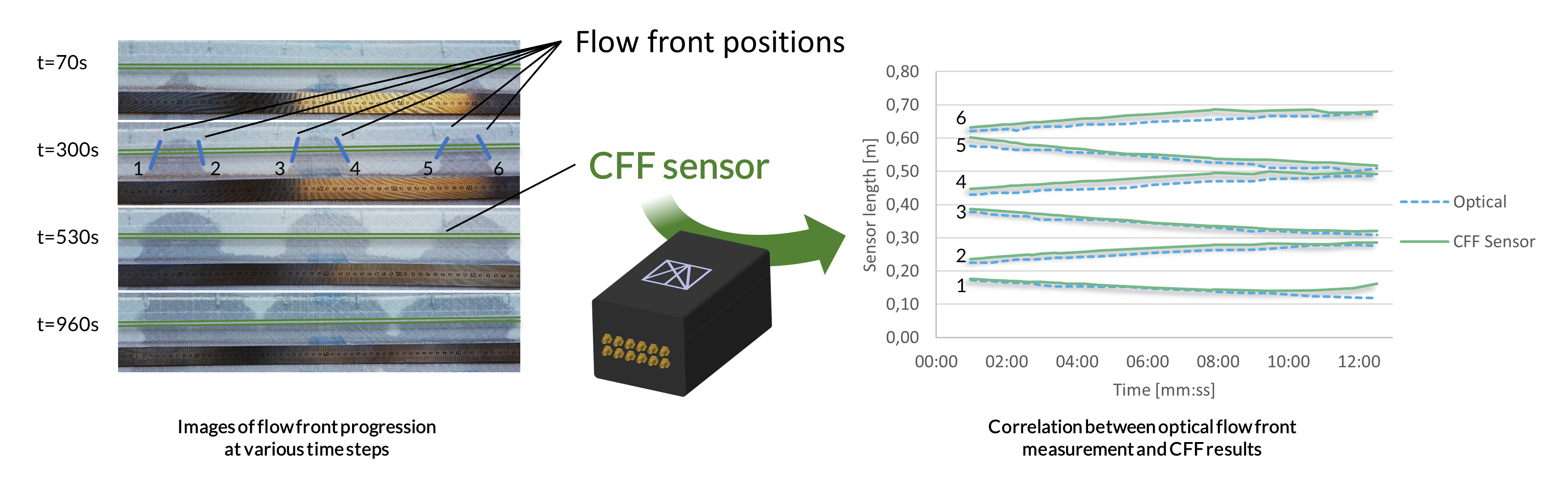
CFF-Monitoring allows the detection of multiple flow fronts within a part using only a single sensor line. SOURCE: InFactory Solutions.
Cure monitoring is possible using a variety of technologies, including fiber optics and fiber bragg grating (FBG) sensors (e.g., used by Luna), electrical resistance sensors (e.g., used by Kistler) and also ultrasonic testing (UT) sensors. So why is this form of TDR the best technology for resin infusion of dry fiber composites? “With Fresnel reflection-based fiber optics, for example, you are limited to monitoring the cure at the end of the fiber,” says Buchmann, “thus, like many other sensors, these provide merely point-wise cure data in the laminate. There is no other technology that I’m aware of that gives a 2D continuous, spatial measurement of cure across the laminate.”
These TDR sensors, then, will be used like the InFactory AFP sensors, to provide data across the whole part? “You can’t cover the whole part in the same way as an AFP sensor,” Buchmann replies. “You would have to focus on certain data that you need. For example, you would have sensors in certain areas like thick laminates where you need to know cure, or in hot spots in the part, etc. We won’t provide a map of an entire wingskin, but only along the sensor lines that we integrate into the wingskin. You could correlate the resulting data with a model that you have or just use these sensors to ensure that you are within the established process limits by comparing the results against a reference measurement.” He notes that you could run a sensor from the forward edge to rear edge of the wingskin and get data along that entire line. “Some analysis is required to establish where to place the sensors and how to arrange them for the data you want to obtain.”

CFF-Monitoring sensors are connected to a monitoring device and computer, the latter enabling analysis and visualization of resin flow front and cure data via InFactory Solutions software. SOURCE: InFactory Solutions.
Sensor connection
The sensor must be connected into a box which has a connection to a computer, which then collects and analyzes the data using our software. “The box also could be plug & play into a PC which has the software installed,” says Buchmann. This physical connection is similar to how thermocouples are used. “But we are looking at ways to make this easier,” he adds, “for example, using one connector for all sensors on a part.”
Are these sensors hard to place? “Not really,” says Buchmann. “We have different ideas about how we could make it even easier, though. Currently, we place them by hand, but we could also have a ‘smart’ auxiliary material so that no placement is needed by the user. The sensor could already be integrated into the flow media, etc. You could also use an AFP-type head or robot end effector to place the sensor wire.”
He adds that in tests with Airbus Helicopters, sensors have been placed in resin transfer molding (RTM) tools using existing channels, “but we could place it on top of the laminate stack, peel ply or flow mesh, as well.” The sensor wire can be only 0.1 mm thick, so even integrating it into the laminate should not be an issue. “We do have some limits on sensor length,” Buchmann concedes, “but arranging sensors to provide monitoring for a wingskin or fuselage panel should not be an issue.”
Monitoring bondline cure and thickness
CFF Monitoring has also been tested in adhesive bondlines. “When you want to monitor cure and thickness in a bondline,” Buchmann explains, “then you can use two sensor strands – one in the stringer and one in the skin, for example. This allows you to obtain data on bondline thickness along the whole sensor strand.” He says the trials InFactory completed show this is a promising technology.
“We also achieved a good resolution, so we can detect small differences in bondline thickness,” notes Buchmann, adding that the sensor line is very small. “We believe we can make them so small that thy don’t affect the bondline and can also be used for structural health monitoring long-term.” Eventually, moisture or cracking in the bondline could be detected.
Timeline for commercialization
“We have proven that this sensor works with different fibers and tooling through tests with Airbus Helicopters and RTM tooling,” says Engel. “The next step is to turn this into a commercial product.” Current development includes improving signal quality by reducing attenuation from conductive fibers and tooling, and exploring how to evaluate the data from the sensors in a way that is meaningful and easy to understand for the process operators. “We can tailor the data provided to needed formats, and different technologies can be used for visualizing the data, including augmented reality, which we have developed for our AFP sensors.”
“So we want feedback from customers in wind and aerospace to see what precisely such a product must look like,” he explains. “For example, how high a resolution is needed and what cost is acceptable, because higher resolution means higher cost. We also want to know which approach is preferred, to integrate the sensors into auxiliary materials or into the laminate? We are getting feedback now from different customers and plan to launch this product within the next 2-3 years.”
Engel notes that InFactory Solutions will sell to companies anywhere in the world, in any industry and also to R&D prototyping projects for use in establishing robotic and digital manufacturing process chains. There could also be applications in composite repair.
“The overall vision of InFactory Solutions is the stepwise digitalization of the complete composite production chain. We started with AFP Monitoring and will implement the Cure-Flow-Front-Monitoring next, both with their own business cases. In a next step, we merge the data from both processes to increase the value of that data. That is what we call step-wise digitalization.” says Engel.


Related Content

Prepreg compression molding supports higher-rate propeller manufacturing
To meet increasing UAV market demands, Mejzlik Propellers has added a higher-rate compression molding line to its custom CFRP propeller capabilities.
Read More
Otto Aviation launches Phantom 3500 business jet with all-composite airframe from Leonardo
Promising 60% less fuel burn and 90% less emissions using SAF, the super-laminar flow design with windowless fuselage will be built using RTM in Florida facility with certification slated for 2030.
Read More
Revisiting the OceanGate Titan disaster
A year has passed since the tragic loss of the Titan submersible that claimed the lives of five people. What lessons have been learned from the disaster?
Read More
Cutting 100 pounds, certification time for the X-59 nose cone
Swift Engineering used HyperX software to remove 100 pounds from 38-foot graphite/epoxy cored nose cone for X-59 supersonic aircraft.
Read MoreRead Next

Dialing in composites performance via dynamic digital twins
Sport Dynamics Lab uses Flexdynamics testing, digital models and AI tools to compare designs, materials and systems, enabling optimization with potential for propellers, drones and vibrational structures.
Read More
Post Cure: 3D printed plastic, composite mouthstick designs assist limited-mobility users
Three M Tool and Machine has used its in-house additive manufacturing capabilities to rethink medical devices like mouthsticks, which must be stiff, lightweight and comfortable enough for everyday use.
Read More
Industrial ultrasonic NDT adaptation permits accessible composite bicycle inspection
Cycle Inspect's ASNT-aligned certification program employs affordable twin-crystal ultrasonic testing equipment and standardized inspection methods to detect damage in composite bicycle components.
Read More