


Breaking rules, not foils
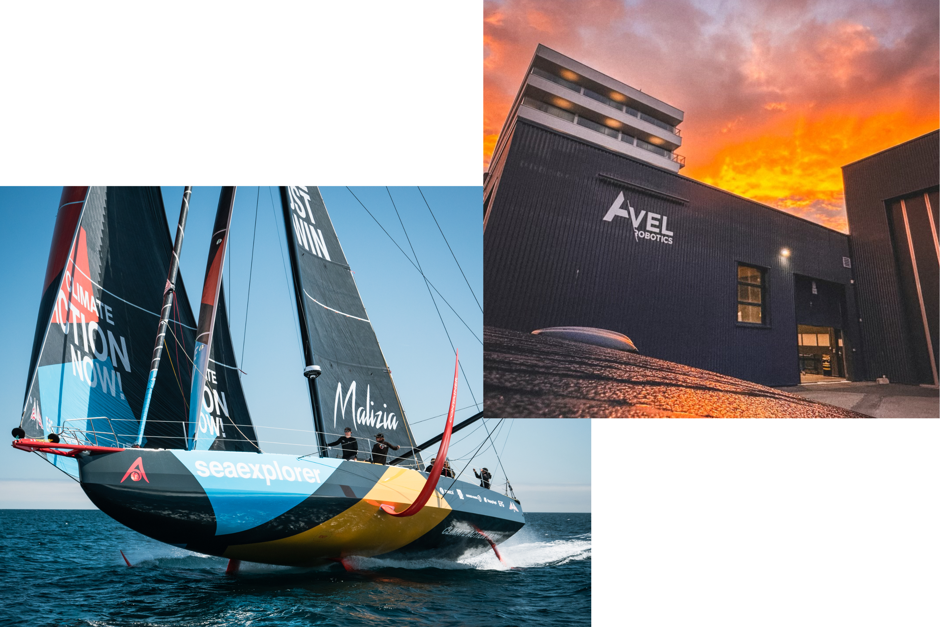
Avel Robotics has pioneered the use of AFP for increased reliability in complex-shaped and -loaded CFRP hydrofoils, used in offshore racing sailboats such as the new IMOCA-class racer for Boris Herrmann and Team Malizia, Seaexplorer, designed for The Ocean Race 2023 and the Vendée Globe 2024. Photo Credit: Avel Robotics © Antoine Louce and © Yann Riou for Team Malizia.
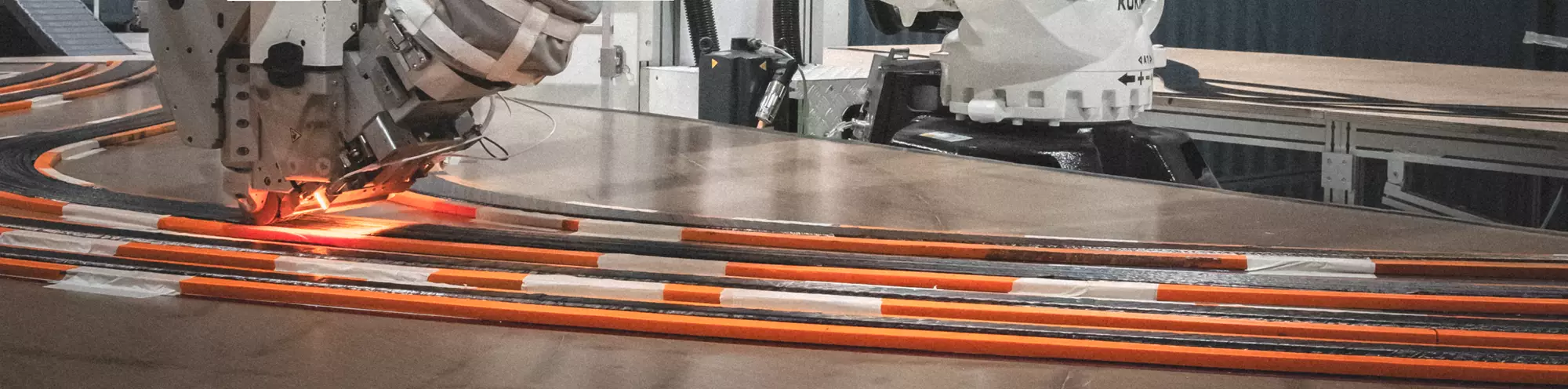
Landscape photo: Avel uses tow steering to “draw” layups for CFRP foil structural components. Photo Credit: Avel Robotics © Antoine Louce
Avel Robotics is located in Lorient, the epicenter of France’s “Bretagne Sailing Valley.” It is home to an ecosystem of at least 50 companies that support the all-composite vessels that compete in offshore racing, including a unique concentration of composites-savvy naval designers and fabricators. Lorient has become “home base” for skippers, teams and their high-performance yachts for competitions such as the Route du Rhum, Transat Jaques Vabre, Americas Cup, Vendée Globe and Jules Verne trophy as well as the myriad races for classes such as Ultim, Figaro, Mini 6.50 and Class40.
Perhaps the most well-known class is IMOCA (International Monohull Open Class Association), comprising 18.28-meter-long monohulls. This class, says vendeeglobe.org, “sees the 60-foot yachts as innovation-oriented laboratories that can help find new solutions for the nautical industry.”


Indeed, this is how Avel was born. Luc Talbourdet, president of Avel Robotics, previously managed an IMOCA team that had decided to invest in carbon fiber-reinforced polymer (CFRP) hydrofoils in 2016. These appendages can lift boats out of the water to “fly” above the surface — that’s 8-10 metric tonnes moving at up to 30 knots/56 kilometers per hour. Daggerboard foils also provide significant sideforce underwater and righting moment to counteract the heeling moment of an IMOCA yacht’s massive sails.
“There was a problem, because some of the hand-layup prepreg foils were breaking,” notes Talbourdet. Issues included variability in quality and delamination. Adrien Marchandise, co-founder and now Avel’s CTO, had been hired by Talbourdet to complete his PhD research on making foils using automated fiber placement (AFP). After significant investigation, the two saw a path for more reliable, high-performance foils and Avel Robotics was formed in 2017.
“We were the first to manufacture nautical foils using AFP,” says Talbourdet. “It is imperative that foils are reliable, and using robot-based AFP brings both quality and repeatability of the layup. It also reduces layup time and dramatically reduces carbon waste.”
Avel Robotics owns two Coriolis Composites (Quéven, France) C1 AFP machines, each applying up to eight tapes with a layup precision of ±0.2 millimeters. The company has progressed from 15-kilogram foils for the first 26-foot catamaran for the Easy To Fly class (ETF26) to its current 300-kilogram foils for top IMOCA skippers such as Boris Herrmann and Samantha Davies. Avel will equip half of the latest generation “foilers” engaged on the next Vendée Globe race — an impressive achievement, the company points out.
Avel has grown to 28 employees and has doubled its turnover to reach €2.7 million in 2022. In five years of production, it has delivered CFRP parts for 57 projects in offshore racing, naval and defense applications, and is now pursuing opportunities in the aircraft industry. ISO 9001 certified since 2018, Avel has completed a test program for one aircraft OEM and is in discussions with a variety of other small to medium aircraft companies. “We already make wings for boats,” says Talbourdet. “We have the AFP capacity to help companies who can’t or don’t want to buy their own machines, but more importantly, we have the digital design and complex composites fabrication expertise to truly add value.”
Complex 3D design
IMOCA boats can have five appendages total — typically twin rudders, twin daggerboards or hydrofoils on the sides and one keel at the hull bottom. Avel has produced rudders, daggerboards and hydrofoils. The latter are typically larger and have more shape. For IMOCA boats, they can be described as C-shaped and, while sailing, can look a bit like upturned whale fins, albeit very long and thin. They actually have a somewhat S-shape, thanks to a “shaft” section that attaches into the hull and allows the foils to be extended and retracted. The 300-kilogram hydrofoil mentioned above measures 6-8 meters long with a 0.5-meter radius in the curved elbow.
“One pair of hydrofoils takes one month for design and five months to produce,” says Marchandise, who leads the tour through an initial layup area as we enter Avel’s main production hall. “We receive a 3D shape from the designer and then create a structural design using 3D Experience (Dassault Systèmes, Vélizy-Villacoublay, France).” This software platform includes Catia and SolidWorks plus other CAD and CAE tools. “Our design includes many different parts that will be assembled.” These include the main load-carrying spine, or stock, foam sections and a trailing edge and leading edge. “We produce all of these different parts using a variety of techniques,” says Marchandise. “We then assemble these 3D puzzle pieces.” The result is a very complex, highly loaded and weight-optimized hydrodynamic structure.
AFP stocks
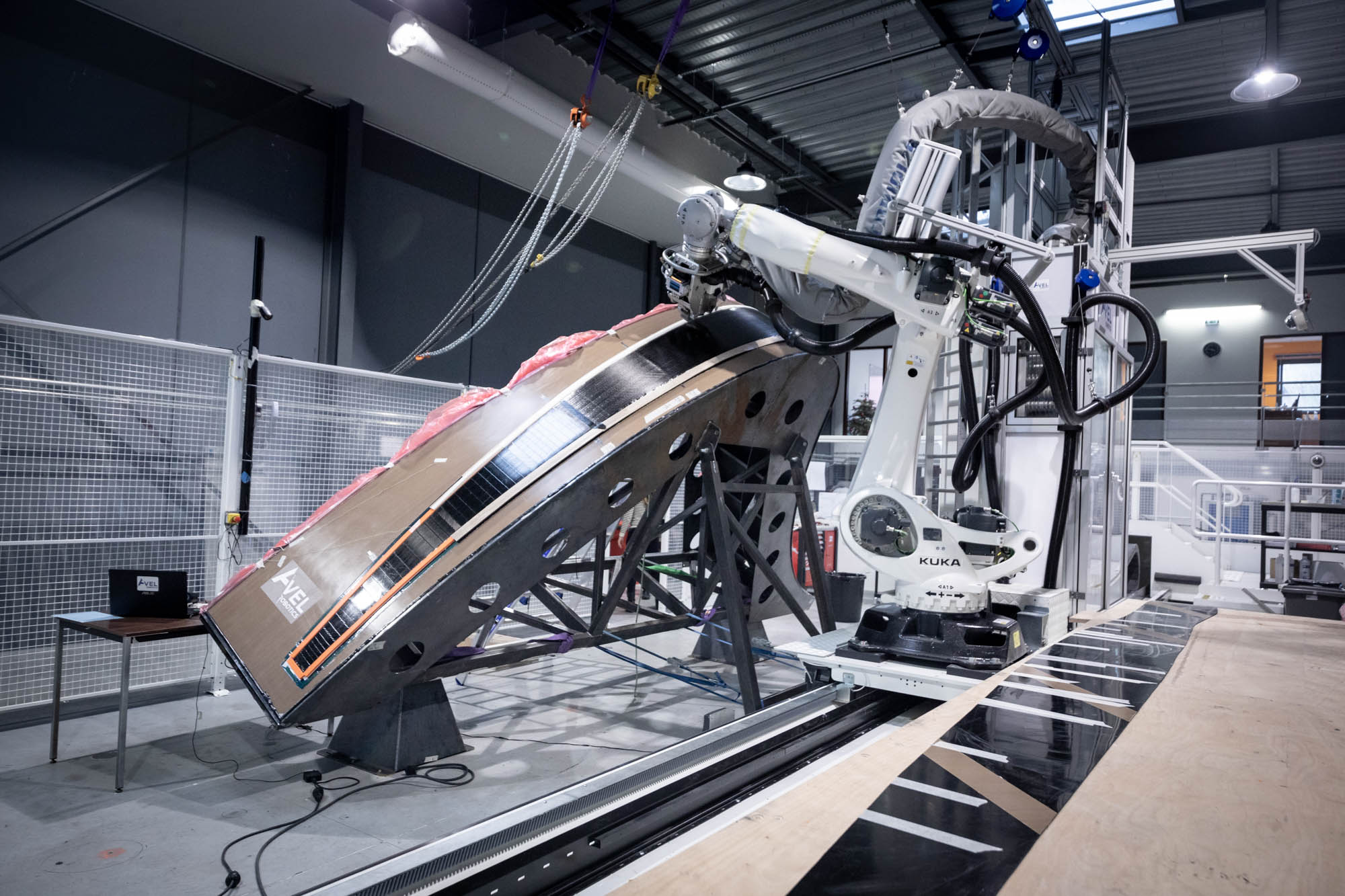
Fig. 1. Foil stock made using AFP
Avel uses AFP to create a foil’s central load-carrying stock. This stock can be made by placing prepreg tape directly onto a shaped tool. An alternate method is shown in Fig. 2. Photo Credit: ©Eloi Stichelbaut for polaRYSE and Team Malizia (top), Avel Robotics © Antoine Louce (bottom).
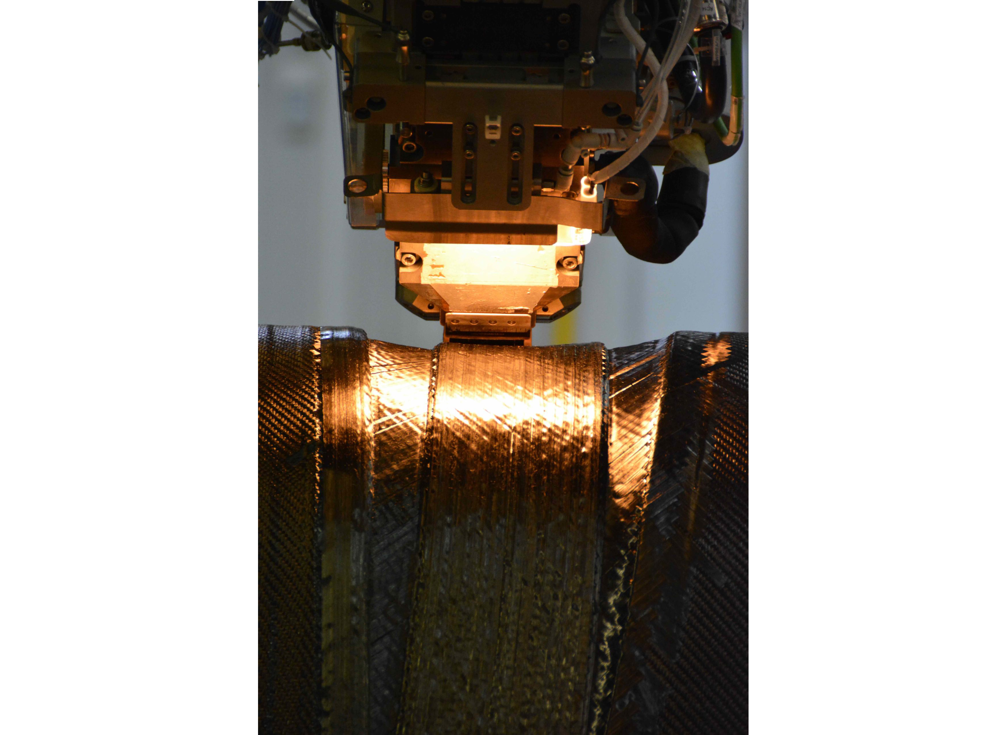
“AFP is used mainly for the stock,” says Marchandise, “which is the primary structure for the foil.” There are two ways these stocks can be made. One is to place the unidirectional (UD) prepreg tapes onto a curved mold (Fig. 1) and then cure them in an autoclave.
Alternatively, the stock can be built as a series of precured curved plates that are then bonded with epoxy adhesive and cured again in Avel’s 2.3- x 5.4-meter Daxen (Malissard, France) autoclave to form a bonded assembly (Fig. 2). One advantage of this method, notes Marchandise, is that the plates are made on a layup table, which avoids the time and cost of building a tool.
As Marchandise explains this second technique, we walk past just such a series of curved, AFP laminates on a table, prepared for autoclave cure with thermocouple cables extending from the layups. “We AFP onto a flat mold table using tow steering to ‘draw’ the curved stock plies. The stock width is also not constant but narrows toward the foil tip. We use a variety of fiber orientations, designed to handle the loads in each region.” These include 0° plies that follow the longitudinal axis of the foils and 90° cross-plies.
“We also use 45° plies in the curve of the foil to increase delamination resistance from shear forces,” says Marchandise. “This is an added value of our design and AFP approach because we have a higher granularity in our ability to tailor the number and orientation of plies at each section. We design each ply, working in cooperation with the naval architect for the foil and the sailing team to achieve the performance desired.”
These flat but sinuous stock layups use toughened epoxy prepreg from Hexcel (Stamford, Conn., U.S.) or Toray (Tokyo, Japan) reinforced with intermediate modulus (IM) or high modulus (HM) carbon fiber. Completed layups receive a metal caul plate and are vacuum bagged, followed by autoclave cure at a pressure of 7 bar for 24-72 hours. Cure temperature ranges from 80-180°C depending on prepreg supplier and type. “Laminate thickness drives cycle time due to exotherm,” notes Marchandise, adding that five such parts are typically cured in the same autoclave cycle.
Battens, foam and resin-infused skins
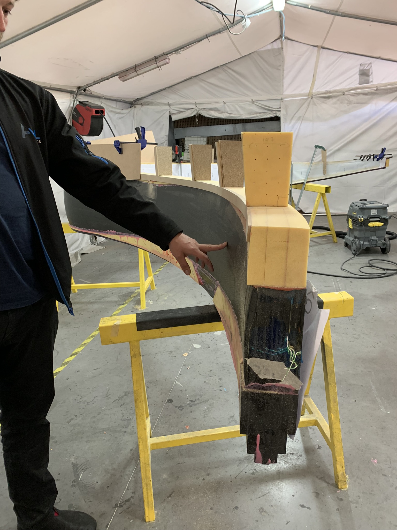
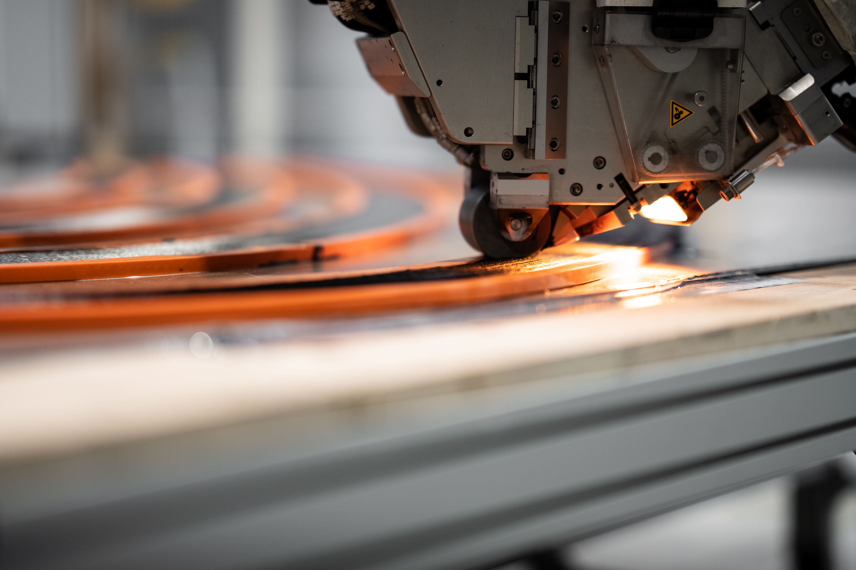
Fig. 2. Stock manufacturing using pre-cured plates
A foil in progress (top) shows a stock with Corecell foam sections being bonded on. Note the foil tip at the right of the photo. This stock is made from curved plates — using AFP layup onto a flat table (bottom) — which are then autoclave cured, sandwiched with epoxy adhesive in between the plates and autoclaved again to form an integrated stock structure. Photo Credit: CW (top), Avel Robotics © Antoine Louce (bottom)
The tour has now moved into a tented enclosure inside an adjoining production hall, where a foil is in the process of being constructed (Fig. 2). A completed multi-plate stock can be seen with foam sections adhesively bonded on top and bottom — the foil is on its side, its leading edge facing the floor.
This stock will form the center of the foil’s architecture, which is comparable to that of a wind turbine blade. Corecell foam core from Gurit (Wattwil, Switzerland) has been bonded on either side of the stock to help withstand impact from unseen floating objects in the water.
Leading edge and trailing edge inserts will be bonded outside of the foil sections to complete the airfoil-shaped chord. These inserts follow the same curve as the foil and narrow at its tip. They are also made from multiple plates called battens, produced via AFP and autoclave cure (Fig. 3).
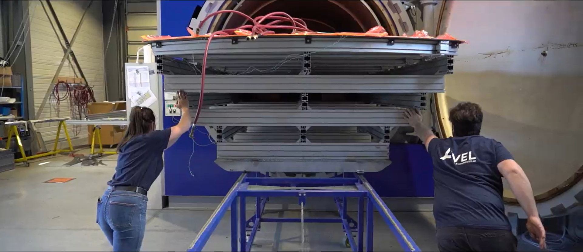
Fig. 3. Autoclaving battens
Spar plates and battens made using AFP on flat tables are shown here being loaded into Avel’s autoclave for cure. Photo Credit: Avel Robotics © Antoine Louce
“We then stack the battens on top of each other and dry fit them to see if the metrology quality is good enough,” says Marchandise. After metrology requirements are met, adhesive is applied to each batten, and the stacks are autoclave cured per the same process as for the multi-plate stock, becoming integrated leading and trailing edge inserts. These triangular prisms taper from the widest battens that mate with the foam sections to the narrowest battens that form the acute outer edges of the leading and trailing edges (Fig. 4). “We then bond these to the foil using epoxy adhesive,” says Marchandise.
Fig. 4. 3D CFRP foil
A foil is being finished, shown from the end that will attach into the sailboat hull. Bonded foam and CFRP batten sections that comprise the foil’s trailing edge can be seen at top. Photo Credit: Avel Robotics © Yann Lhuisset
The result is shown in Fig. 4, the foil on its side and seen from the end that attaches into the hull. A cured batten stack forms the trailing edge insert bonded on top of the light-colored stripe of foam (the foil tip is off to the left, not shown). Beneath the foam is the foil’s stock structure, with the leading edge insert bonded at bottom.
The next step is to apply the skin. “We hand layup dry quasi-isotropic plies around the bonded structure and infuse it with epoxy resin from Sicomin [Châteauneuf les Martigues, France],” continues Marchandise. “We can’t use prepreg because the foil’s chord length will gain two to three millimeters when it cures due to thermal expansion. This dilatation of the composite primary structure, which is positive through the thickness, causes springback issues in the skins [i.e., deviation in the molded shape due to thermal effects]. To avoid this, all skins are made using wet layup or infusion. To use prepreg, we would need one that cured at 40°C.”
Cost vs. performance
This multipiece, multistep foil construction seems incredibly complex. How is it possible to compete with foils made using only hand layup?
“It is a bit more expensive,” says Marchandise, “but we also make much more efficient use of materials. For example, HM carbon fiber is twice the price of IM fiber. We tailor the laminate to use HM fiber only where we need stiffness. This is harder to do in hand layup, where they typically end up with three-fourths of the laminate in HM fiber. Thus, we actually reach the same price with our technology.”
“But,” he points out, “our structure is much better in strength because it is a truly 3D-optimized structure. The fact that we are using both types of fibers in all the directions gives a performance that we wouldn’t be able to achieve using hand layup alone. Our structures are much less susceptible to delamination, so damage tolerance is much higher. And that was the whole goal in the beginning — to have foils that won’t fail. For example, if you hit something very hard in the middle of the tip, in a typical hand layup structure, the result is delamination, and it will then zipper along the foil. In our construction, any break at the impact point is localized. You just unglue the battens, replace the damage at that location and reassemble the edge insert.”
4D composites
Avel Robotics describes the structures it makes as 4D composites. “We must optimize our structures not just for loads in three dimensions, but also over time,” explains Loeva Malacarne, business development manager, who joined Avel Robotics in 2021 after 11 years at Safran. “We analyze the performance of our products closely during design, production and in service so that we can get a better lifetime prediction for the composites, which we use to improve our designs and processes going forward.”
The tour has now moved back through the production hall and up onto a mezzanine at the far end, where dozens of test coupons (Fig. 5) are stored. The 4D process, says Marchandise, starts with design. “We do coupon tests as well as full-part tests with full-scale loads at the University of Southern Brittany, which is local,” he explains. “The coupon tests supply the FEA [finite element analysis] with accurate input data — the goal is to manufacture what you design. For this to be realistic, we manufacture actual subelements and extract coupons from those in order to reflect the manufactured part including AFP, curvature, thermal profiles during cure, etc. This can’t be left to others because it’s our manufacturing process.”
“The second testing approach is to use very large coupons to check that the structure behaves the way we want it to behave,” Marchandise continues. “In certain load cases, we want compressive strength on the inner surface and we want strain before interlaminar delamination. We use larger scale testing with more representative loads to check this and also the damage mechanisms in the material as manufactured. We also extract coupons from the different parts of the subelement and send their test values to the naval architect for integration into the FEA.”
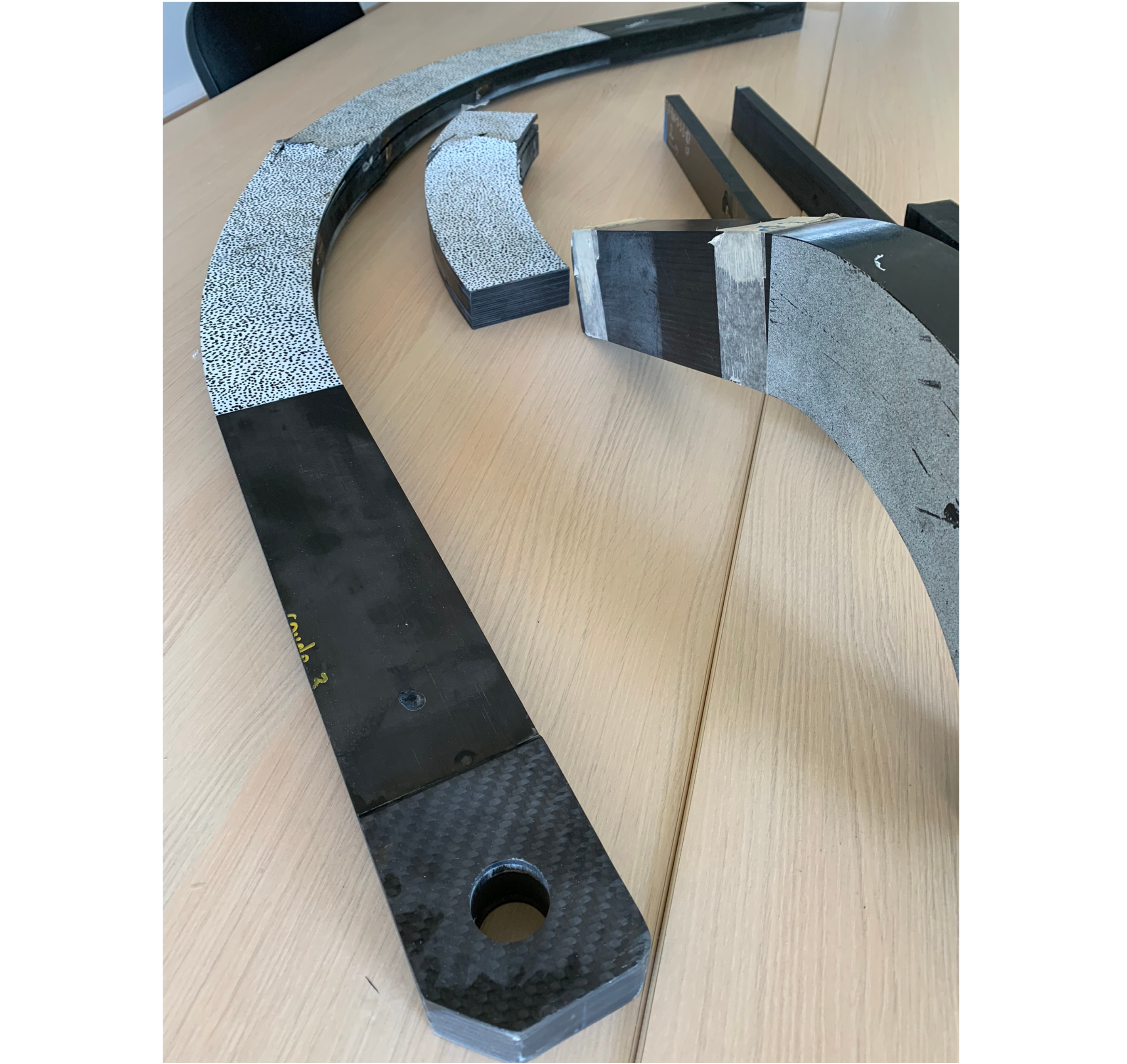
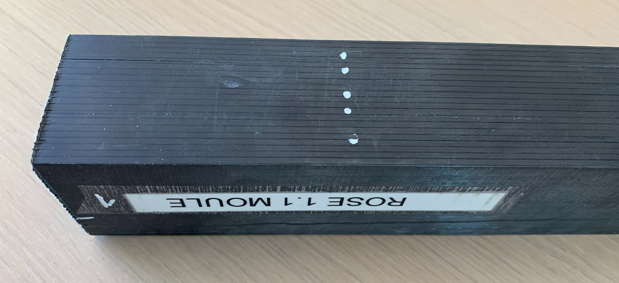
Fig. 5. 4D composites
These subelement test specimens (including DIC samples, top) are used to provide as-manufactured material data, plus structural and failure data used as input and validation for FEA, improving design accuracy and Avel’s ability to predict a part’s performance through its service life. Photo Credit: CW
Some of the test samples on Avel’s mezzanine are broken and covered in a random paint pattern indicative of digital image correlation (DIC), which captures and analyzes images during testing to produce full-field strain distributions.
Marchandise explains that Avel uses DIC “to check that the strain field looks like what we have on the FEA model. It’s more a qualitative check versus quantitative. We use more accurate strain gauge sensors for quantitative results and when we break these subelements, we will have eight acoustic emission sensors to give us a fuller picture of the damage.”
Is this testing completed for every new design? “Yes,” says Marchandise, “but not so much is needed if we’re just scaling in size.”
At this point in the tour, Talbourdet picks up the discussion. “Now we’re implementing static tests of the existing foils to increase our knowledge and get the full loop back into the design and manufacturing process. We have recruited people to do just that through a Bureau Composites department. And this also helps us to stay in partnership with our clients and understand what they will need for the next design.” This new department in Avel will also explore bio-sourced materials for its AFP machines.
Flying, from foils to aircraft
The quality built into Avel’s structures via its 4D approach has brought success. The company has built 19 pairs of foils since 2017 and attracted similarly innovation-focused partners, like the designers MerConcept (Concarneau, France) and the IMOCA teams L’Occitane and Apivia, the latter placing first or second in six major races since 2019. “The MerConcept design company started with us in 2018,” says Talbourdet. “They saw what they could get from the quality of our parts, and now we have built parts for four boats. If we had not delivered value, that business would not have continued.”
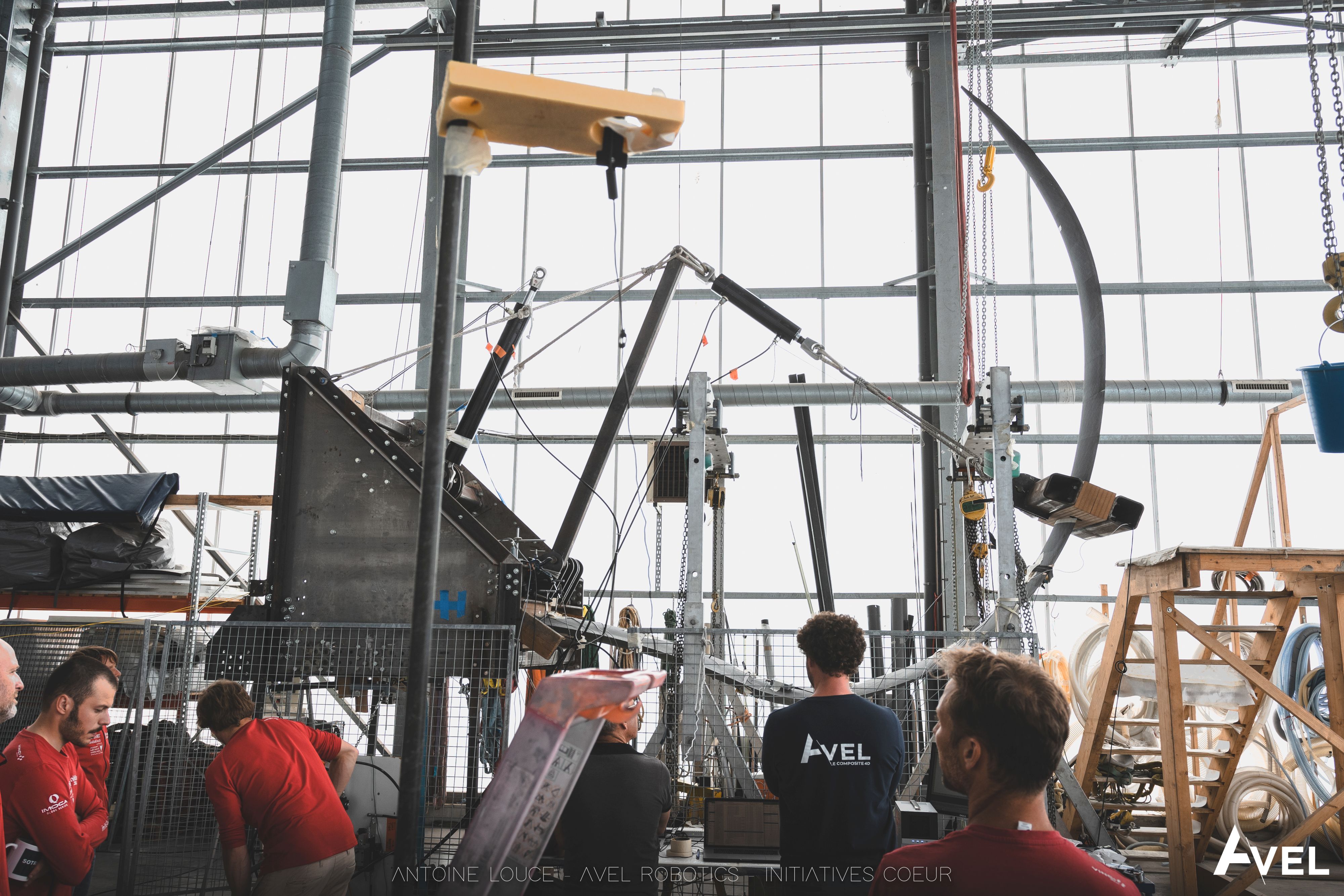
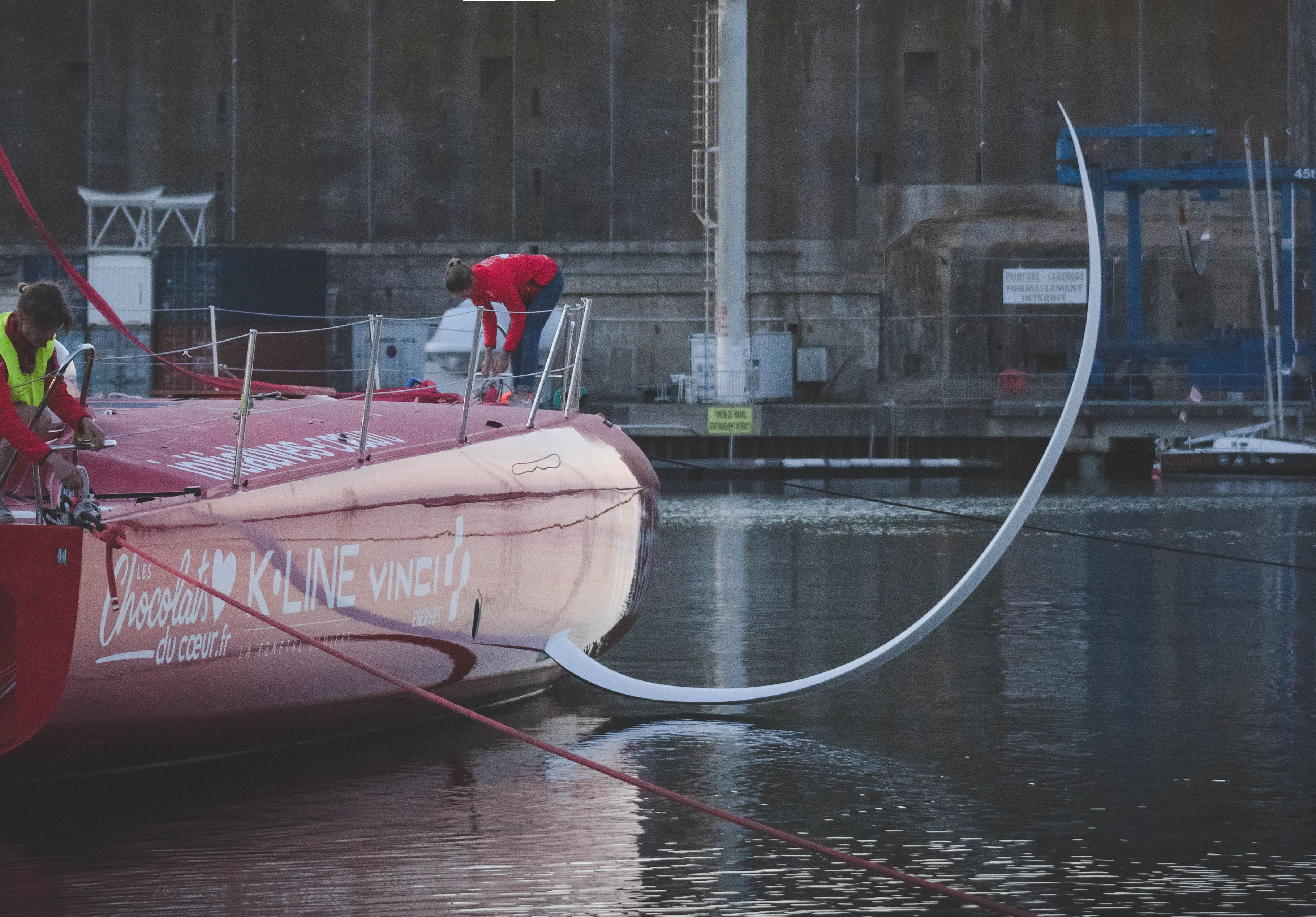
Fig. 6 Static tests, durable foils
Static test of an Avel Robotics CFRP foil and subsequent boat launch with that foil installed. Photo Credit: Avel Robotics © Antoine Louce
The goal now, he says, “is to continue increasing our market share of structural parts for IMOCA, Ultim and other racing boats. We see continued growth in the yachting and naval markets because customers are also looking for a lower CO2 footprint — Avel Robotics delivers at least a 50% reduction in carbon fiber composite waste compared to traditional hand layup.”
Talbourdet acknowledges that Avel must stay in tune with the nautical industry’s innovators and their push forward. “But we are also moving forward,” he says, “and becoming more efficient in our designs and processing.” Indeed, in 2020, the company bought its second AFP machine and reported a significant improvement in layup time. Now Talbourdet believes Avel can offer this quality, reliability and innovation to the aircraft industry.
Why aircraft? “Because we’ve got the skill and tools to make aeronautical parts,” says Talbourdet, “and we also have a unique AFP capacity. And if you look at the market, there are maybe 10 or 15 AFP machines in Europe, but not many companies that will commit to deliver aerospace-quality AFP parts at a fast pace for a set price. There are a lot of Tier 2 suppliers still using manual methods.”
Why is Avel’s AFP capacity unique? “Because we can produce serial parts, for diverse applications,” says Malacarne. “We are not a technical center or a fab lab focused on prototyping. If tomorrow a customer wants 100 identical parts, we’ll deliver.” This capability also includes expertise in structures that are complex and highly loaded, but may also scale up in size (see sidebar “Massive AFP mast for next-gen cruise ship” below)
“We’re targeting small to medium aircraft companies that are moving toward more sustainable aviation and either can’t or don’t want to invest in AFP robots,” he continues. “So, we’re filling a gap, but we’re also changing how value is delivered. We are building a fully digital chain that doesn’t currently exist, even in parts of the aerospace industry.”
Talbourdet explains that it is still common, even among some aero-industry companies, “to get data where you don’t know how it was built — you don’t have one set of files going from the start of the process to the end.”
“We are already designing parts for AFP and producing those parts,” says Talbourdet. “The companies we are meeting with are very surprised at what we know and the parts we’re making and they are very interested.” He adds that Avel is seeking to complete a demonstration project with aircraft manufacturer Dassault Aviation (Paris, France) and is in negotiations with some European OEMs for CS-23 airplanes (an EASA certification for certain types of general aviation and commuter aircraft) and next-gen decarbonized aircraft projects.
If we were normal
In the end, says Talbourdet, this next step forward is the same as what Avel has taken in marine. “When you come with a new solution, people will say it’s not realistic, technically feasible or affordable. But we entered the market and succeeded. And now it is the same in the aeronautical industry. I mean, if we were a normal company, we wouldn’t do this, because it’s more risky than just doing the same thing. But now aviation is asking for innovation and demanding it. To move away from hand layup was a big step and our success was not guaranteed. But we believed in our approach and we are now enabling even further innovation. We understand the process of disruption — you can’t go forward if you’re staying in place.”
Massive AFP mast for next-gen cruise ship
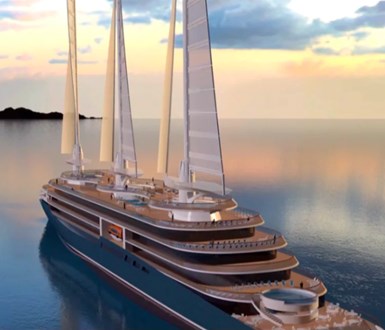
Photo Credit: Chantiers d’lAtlantique
The largest structure Avel Robotics has made was for the SilenSeas sailing cruise ship concept developed by the French shipbuilder Chantiers de l’Atlantique (Saint Nazaire). The 200-meter-long cruise ship will have three 80-meter-high CFRP masts that can be tilted at 70° to pass beneath bridges. Each mast will rotate 360° and be equipped with a CFRP solid sail, made from rigid panels that fold like an accordion when lowered. This system, referred to as Solid Sail/AeolDrive, is designed to reduce fuel consumption by 30% versus a conventional ship.
In 2021, Avel Robotics joined a Lorient-based consortium including composite multihull boatbuilder Multiplast, CFRP mast and spar fabricator Lorima, composite mold builder SMM and Avel’s neighbor CDK Technologies, which specializes in prototyping novel offshore sailing yachts. The companies collaborated to build one section of the 25-meter-high demonstrator mast, representing just the top section of a SilenSeas rig. The demonstrator, equipped with a 550-square-meter CFRP sail, was installed in 2021 and tested in 2022. The next step will be construction of a full-scale mast and sail.
Avel produced the AFP layup for a 10-meter-long mast section half-shell that weighed 1.2 metric tonnes with a 65-millimeter-thick laminate. “That was the first time we built such a big part,” says Talbourdet, “and it was also the biggest part built with a Coriolis C1 machine. We needed some help, actually, because we were beyond the limit of the machine, and we worked with Coriolis to amend the software.”
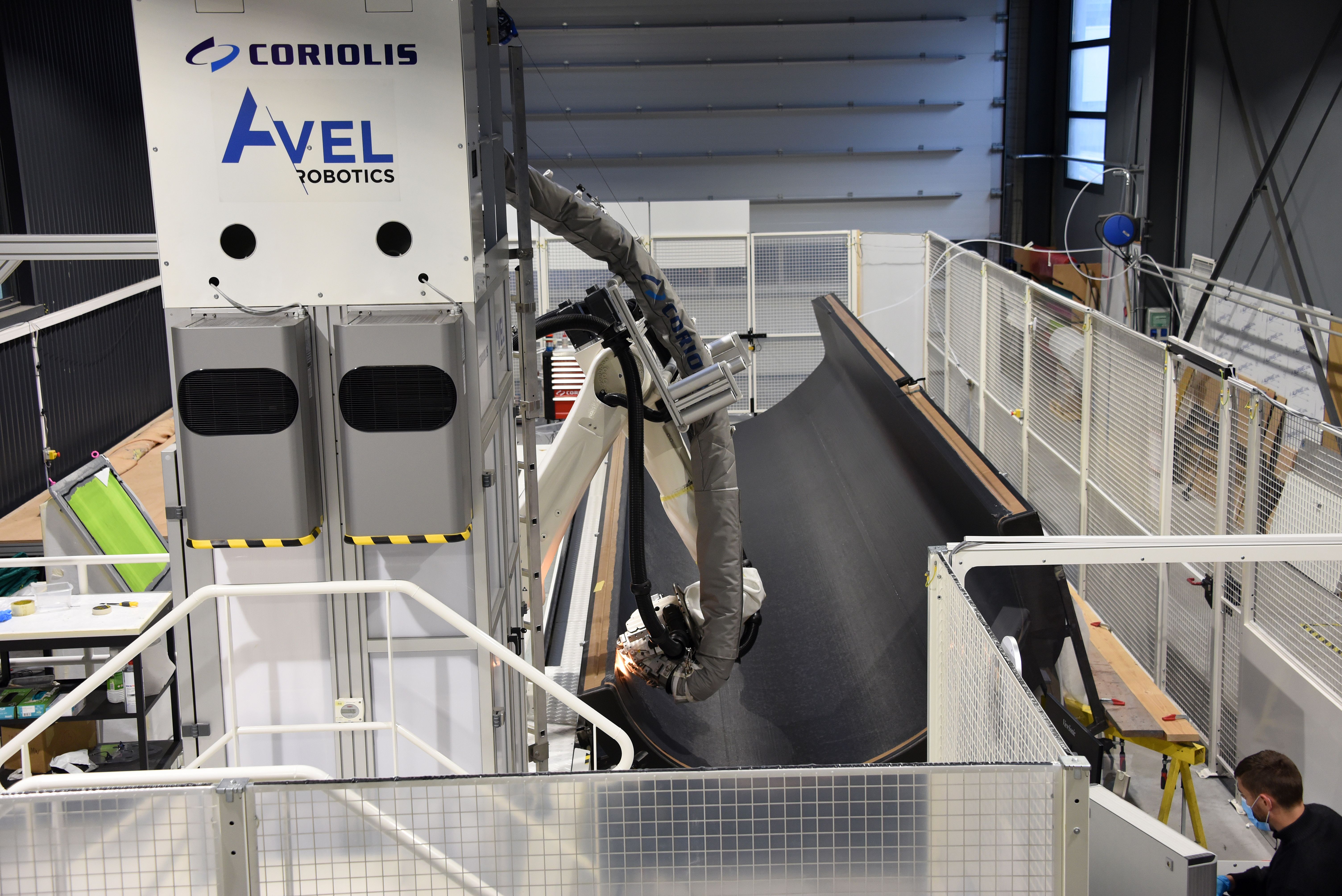
Photo Credit: Avel Robotics © Antoine Louce
Was the large size a challenge? “I don’t think size is ever really a limit,” says Talbourdet. “There's always a way with rails and gantries.” Avel’s C1 machines are based on KUKA (Augsburg, Germany) robots and mounted on rails with a build envelope of 3 x 10 meters. “We have pushed the limits of the C1 machine more in terms of tight radius and complexity of the layup paths,” he adds. “We are always pushing limits, but Coriolis has used our feedback and made the machines better.”
Where will this project lead? “Neoline [Nantes, France] has placed an order and Chantiers de l’Atlantique is talking to other potential customers,” says Talbourdet. “But this project showed that Avel can produce such a large, demanding prototype on time and on budget. So, why wouldn’t we do this now for series production?”


Related Content

ORNL demonstrates lightning strike protection tech for composites
Researchers, led by Vipin Kumar, developed a low-cost, recyclable carbon fiber wind turbine blade tip that showed resilience to high-voltage lightning strikes, with more innovations in store.
Read More
Determining steel/composite failure load of bonded repair assemblies
Bureau Veritas and partners use a novel equivalent interface test specimen and simulation to predict failure load in bonded composite patch repairs to steel structures.
Read More
Schrödinger advances materials informatics for faster development of next-gen composites
Cutting time to market by multiple orders of magnitude, machine learning and physics-based approaches are combined to open new possibilities for innovations in biomaterials, fire-resistant composites, space applications, hydrogen tanks and more.
Read More
Proving thermoplastic composites match carbon fiber/epoxy performance in road bikes
CDCQ, LxSim, Addcomp and Argon 18 collaborate to optimize a carbon fiber/PA6 bike seat post, democratizing AFP and demonstrating materials and process for future designs and production.
Read MoreRead Next

Plant tour: ÉireComposites, Galway, Ireland
An in-house testing business and R&D focus has led to innovative materials use and projects in a range of markets, from civil aerospace to renewable energy to marine.
Read More
Carbon fiber composite hydrofoils to enable “world’s fastest” electric ferry
The Candela P-12 Shuttle, set to launch in Stockholm, Sweden, in 2023, will incorporate lightweight composites and automated manufacturing to combine speed, passenger comfort and energy efficiency.
Read More
Post Cure: CFRP mainframe, modern manufacturing techniques pioneer next-generation rigid airships
Advanced composites enable the revival of rigid airships in LTA Research's 400-foot-long Pathfinder 1.
Read More