


Four-piece preform for resin-infused ring frame
Airbus Helicopters’ redesign of the aluminum H135 ring frame to carbon fiber-reinforced epoxy uses already qualified, bindered dry fabrics, shaped using four preforming tools, into the 1, 2, 3A and 3B preforms shown here, and assembled along with an unreinforced polymer gusset filler (shown as 4) to comprise a single-piece primary structure made using cost-effective resin infusion and oven cure. Photo Credit for all images: Airbus Helicopters
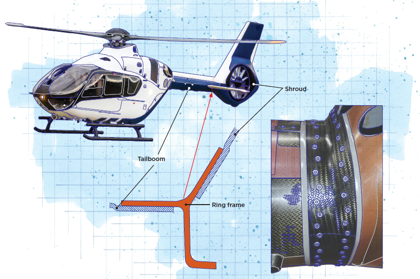
The H135 light twin-engine helicopter is reportedly the number one emergency medical service (EMS)/air ambulance helicopter in Europe, known for its reliability, versatility and cost-competitiveness. Also used for search and rescue, military, police and support flights for wind farms and other offshore facilities, the H135 is manufactured by Airbus Helicopters in Donauwoerth, Germany, and features the company’s signature Fenestron shrouded tail rotor. Touted by Airbus Helicopters as having the lowest operating and maintenance costs in its class, more than 1,350 H135 helicopters are in service in more than 60 countries, and are relied on by more than 300 operators.
Over the years, as the H135 fleet increased in flight hours, routine maintenance at regular intervals revealed that fatigue and corrosion problems could arise on the aluminum ring frame that connects the carbon fiber-reinforced polymer (CFRP) tailboom to the CFRP tail rotor shroud. This required more detailed inspection and increased maintenance costs. To improve inspection and increase the safety standard for the H135, Airbus Helicopters looked for a corrosion- and fatigue-resistant design.
“Our first target was to go to titanium,” recalls Jan-Christoph Arent, senior expert tooling design at Airbus Helicopters Donauwoerth. “But that would have to be machined, which is expensive, and also the raw material is expensive.” The multidisciplinary development team then analyzed composites using prepreg, the Airbus-patented vacuum-assisted infusion process (VAP) and resin transfer molding (RTM). “Compared to aluminum and titanium, a CFRP ring frame provided not only the most robust solution, but also reduced weight,” he explains. “And we developed a design that was less costly than titanium.” This design would be produced using a multi-piece dry preform and VAP.
Illustrated by Susan Kraus.
Meeting design and production requirements
Developing the design for the ring frame presented several issues. The ring frame is a primary structure that connects the tailboom tube with the tailboom shroud. Because the new ring frame replaces an existing part where the surrounding structure could not be changed, design options were limited. “We could not change the tailboom design or the shroud in the interface area,” notes Thomas Kunkel, from the Donauwoerth structures design office. “We had to make a part with the same connecting surfaces and dimensions, but we could change the riveting pattern and the number of rivets.”
After meeting with design, stress and production engineers, the team had enough information to proceed with evaluating RTM, VAP and prepreg. “Our early analysis showed that VAP would be the cheapest way to go,” says Franz Stadler, Donauwoerth innovation department. “So, we then started to develop with the designers a part which we could produce with low recurring costs. We also tried to reduce the tooling costs as much as possible. Therefore, we looked for some standard materials that we already had in production and with which we already had experience.”
The dry carbon fiber fabrics the team chose were already used in other Airbus Helicopter programs. “The strength and sizing models were already well known by our stress department and test laboratory,” says Hans Otto, from Donauwoerth’s industrialization department. The G0986 2x2 twill fabric from Hexcel (Stamford, Conn., U.S.) is stabilized with epoxy binder and is well-suited to preforming for resin infusion. The resin selected for infusion is Hexcel’s one-component RTM6 epoxy that is qualified by Airbus Helicopters for resin infusion and RTM.
However, due to the extreme non-developability of the geometry (a developable surface is one that can be formed readily from a 2D sheet), some cuts and notches had to be designed into the flat preforms to avoid wrinkles as the flat plies were compressed and molded into circumferential layers (see Fig. 1). During preform design, the development and industrialization departments worked closely together to ensure that production was cost effective and in line with the load requirements.
“We saw that we would have to make some cuts in the preforms to prevent wrinkles,” says Antonia Horstmann from Donauwoerth’s stress department. “For certification, we cut several cured ring frames in segments and tested the ring frame sections in compression and in tension. With the compression tests, the crippling strength of the inner flange was tested. Static and dynamic tension tests were performed to test the unfolding capability and the interface between the CFRP annular parts and the unreinforced polymer gusset filler.” These test results showed that the expected loads could be handled safely and the new CFRP ring frame design was robust.
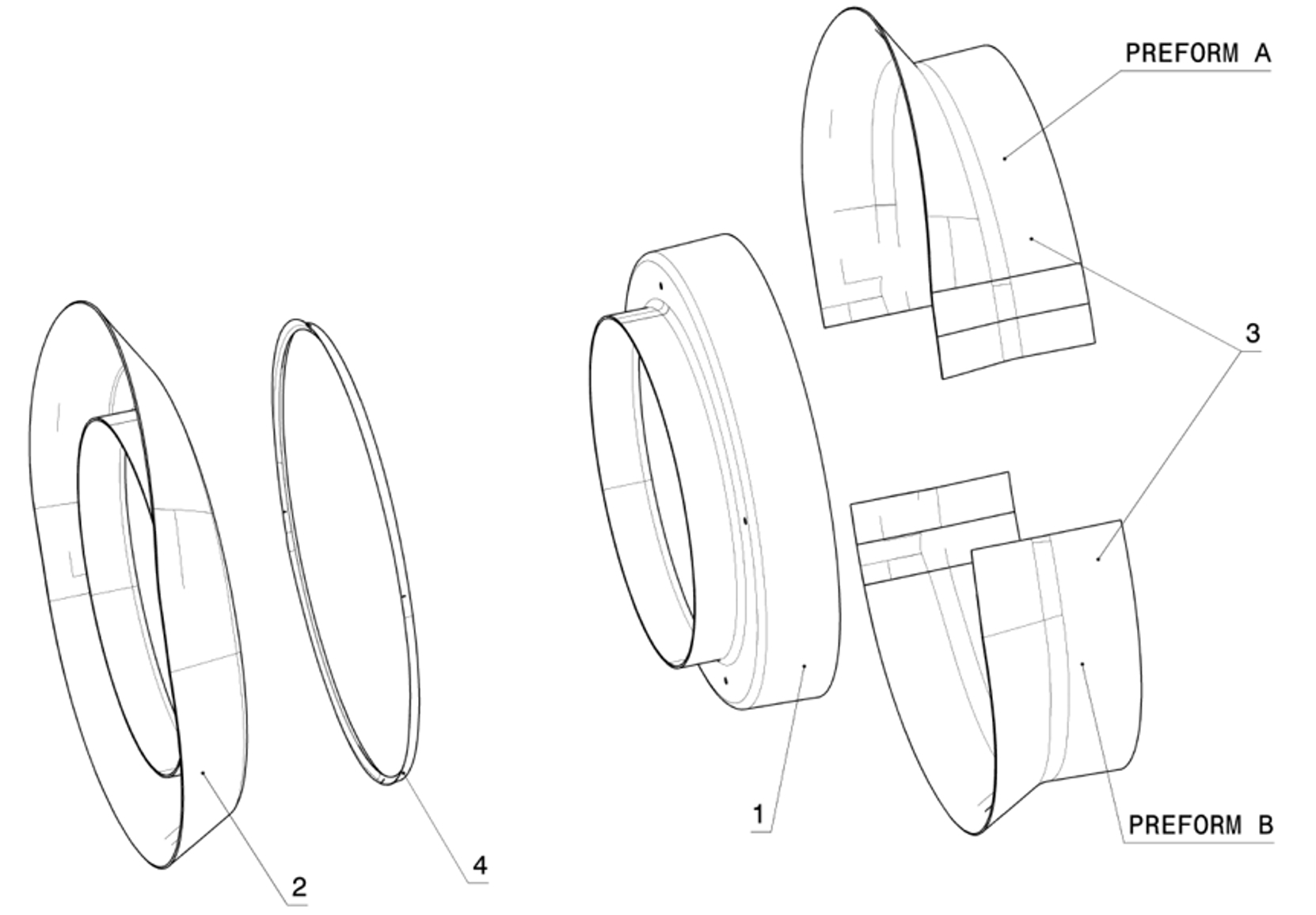
Diagram of the preforms for the H135 CFRP ring frame
Four-piece preform,
single-shot infusion
The idea behind the preform design, says Otto, was to not make too many preform elements, nor too many cuts. “We ended up with four preforms, each a preassembled stack of several layers,” he explains. The image at right shows these four preforms numbered 1 and 2, with 3 including preform A and B. The shape numbered 4 is the unreinforced polymer gusset filler, which ensures a correct layup in the T-connection area. These preforms are manufactured on four special preform tools (Fig. 1) and then assembled into the final configuration along with the ring-shaped gusset filler into the multi-piece curing tool (Fig. 2).
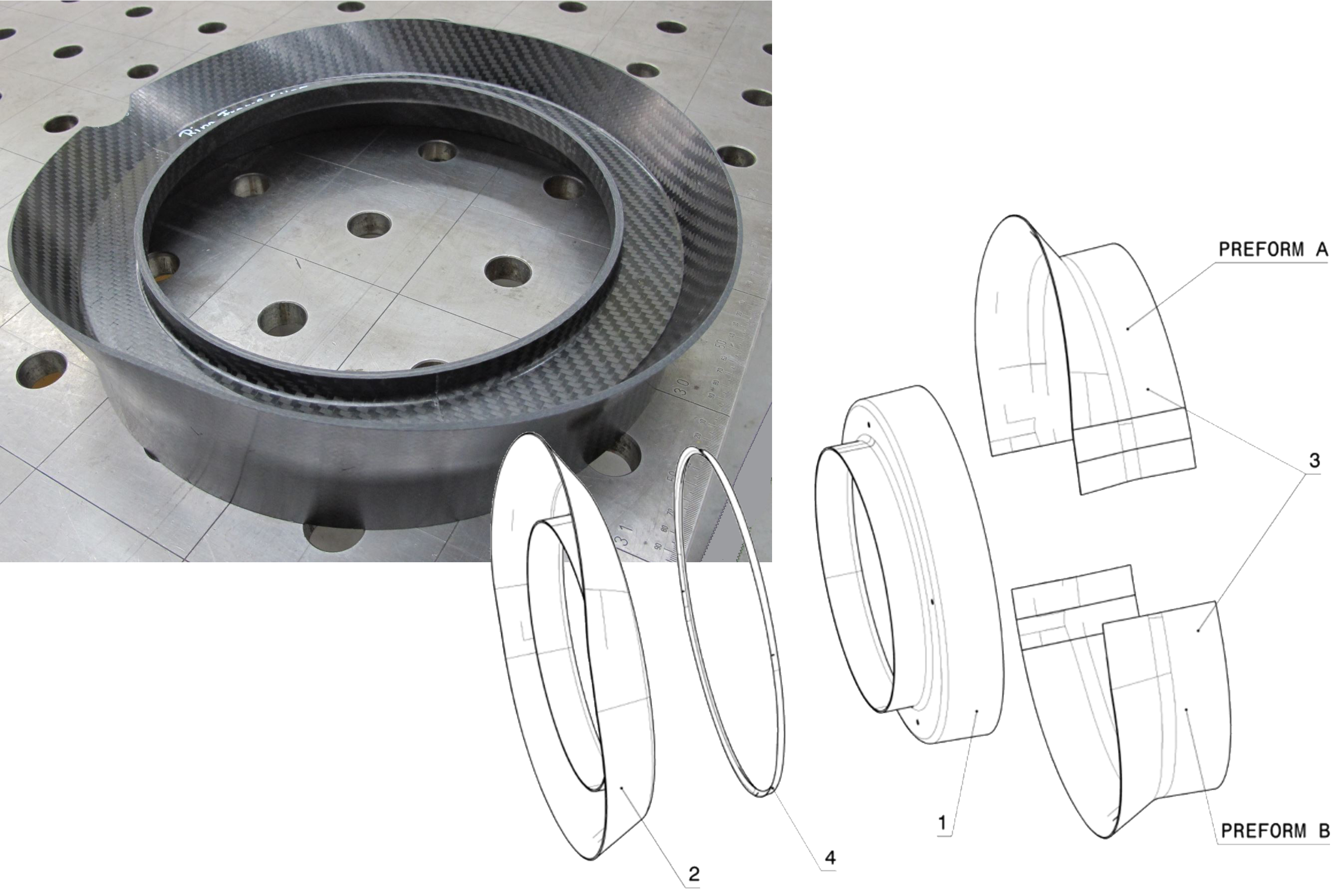
Fig. 1. Preforming tools
Preforming tools were used to create preforms 1, 2 and 3 from the opening image. Preforms 3 and 1 are shown at the bottom of the left (orange) and right (blue) panels. The preform assembly diagram is shown in all three panels, with that preform’s location highlighted in color and the unreinforced gusset filler 4 shown as a triangle. The dotted line shows the center axis of the annular preform assembly. Preforming tools for preform 2 and 1 are shown at the top of the center (green) and right (blue) panels. Note, the C-profile preform 2 is inverted from its preform tool and assembled C facing up. The Z-profile preform 1 forms the bottom of the preform assembly.

Fig. 2. Curing tools
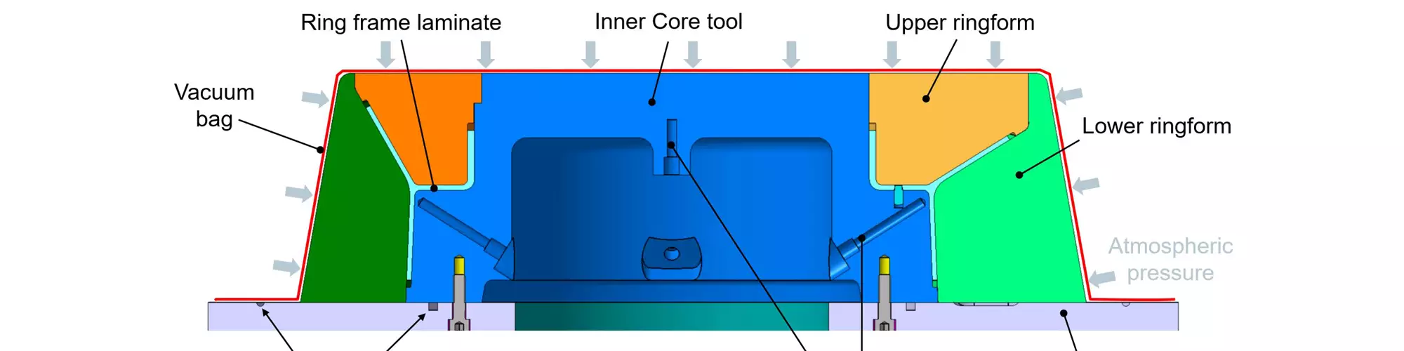
Airbus Helicopters developed a multi-piece aluminum curing tool comprising an inner core tool attached to the base plate and outer tooling split into multi-piece upper and lower ringforms. The assembled preform is shown in turquoise.
Arent describes the cure tooling (Fig. 2): “The complete tooling is made from aluminum alloy. We have the inner core tool [blue] which is fixed to the base plate [gray]. The outer annular tooling [green] and the upper ringform [orange, yellow] are split into segments. This feature prevents thermal clamping forces introduced by the tooling shrinkage during the cooling process after curing.”
The preforms shown in Fig. 1 are assembled in the curing tool and shown in Fig. 2 as a single unit (turquoise). The preform assembly in the curing tool starts with placing the Z-profile preform 1. The gusset filler follows. After placing the C-profile preform 2, the two outer preforms 3 (A and B) complete the stack. “The positioning of the upper and outer tooling completes the process,” notes Arent.
Thermocouples for cure cycle control are integrated into the inner core. After layup and tooling assembly, vacuum bag materials are applied and the preforms are infused with RTM6 epoxy resin.
After layup and tooling assembly, the typical VAP vacuum bag materials sequence is applied, which makes use of a semipermeable membrane. A vacuum soak is then completed at room temperature and the tool and layup are heated in an oven. “You could use a self-heated tool for this infusion, but we are not doing so because we are not producing a volume of parts that demands this,” Arent explains. “The cure cycle has a fast ramp to the first plateau at which resin infusion takes place. After resin filling is complete, we then ramp to 180°C for a standard RTM6 cure cycle. There is no post-cure. After cure, we proceed through cool down and then demold. The part is then ready for edge machining, followed by drilling. The drill holes for the rivets have to be done with high accuracy. Therefore, they are executed in the assembly jig by drilling through the ring frame and the connecting structures [tail boom and tail shroud] in one shot.”
Demolding the CFRP ring frame for the H135.
The part must maintain tolerances of ±0.4 millimeters. To ensure these geometrical requirements were met, Arent explains that a distortion analysis using finite element (FE) simulation was performed. “The results of our chosen part and fiber design showed only some uncritical displacements,” he notes. “With these results, we were confident that our tooling design would achieve the geometric requirements ‘first-time right.’ And indeed, there were no tolerance problems, and no special efforts for hard shimming were necessary. We were able to connect the tailboom, ring frame and shroud using only liquid shim adhesive.”
Program success
The ring frame redesign was completed roughly one year ago, but some additional time was still required before production was switched over. “There were a lot of things we had to ensure — that the design works, as well as all the process steps, and that there is no problem in serial production and tailboom completion,” says Arent. “You have to make sure that the whole process is mastered, not just producing the single part. We also had to make sure that the production instructions in the factory were changed and that everybody was prepared about the new design, even for the surface finish and painting. Everyone had to make sure that it worked before we started with the serial production.”
He adds that training is important, “because when you switch from metal to composite, there are different things you have to know and think about. It’s not only that you make a modification on an existing part, and there are some reinforcements machined, or some additional layers. This was a technology change.” In the end, everything proceeded smoothly and all newly built H135 helicopters are using this composite ring frame.
What was the biggest challenge? “To match the interfaces without making changes,” says Arent. “The tolerances were not really a challenge — those were managed by the tooling development and the selected design quite well. If you look at the tooling diagram, you see the inner and outer tooling builds the interfaces and they came out accurately. It was really the preforming that was the most challenging to make the production process robust and efficient.”
Arent says the redesign is considered a success for several reasons. “By replacing the aluminum design with a corrosion-resistant and fatigue-free CFRP ring frame, the safety standard is significantly increased, inspection measures are improved and we were able to reduce weight by roughly 0.5 kilogram. All these points offer huge advantages for our customers.”


.jpg;maxWidth=300;quality=90;format=webp)
Related Content

PEEK vs. PEKK vs. PAEK and continuous compression molding
Suppliers of thermoplastics and carbon fiber chime in regarding PEEK vs. PEKK, and now PAEK, as well as in-situ consolidation — the supply chain for thermoplastic tape composites continues to evolve.
Read More
Carbon fiber in pressure vessels for hydrogen
The emerging H2 economy drives tank development for aircraft, ships and gas transport.
Read More
Materials & Processes: Resin matrices for composites
The matrix binds the fiber reinforcement, gives the composite component its shape and determines its surface quality. A composite matrix may be a polymer, ceramic, metal or carbon. Here’s a guide to selection.
Read More
Materials & Processes: Fibers for composites
The structural properties of composite materials are derived primarily from the fiber reinforcement. Fiber types, their manufacture, their uses and the end-market applications in which they find most use are described.
Read MoreRead Next

Global Medical Response orders 21 additional Airbus helicopters
GMR equips its growing air medical fleet with the composites-intensive H125, H130 and H135 helicopter families, noting their reliable performance for critical care transport.
Read More
From the CW Archives: The tale of the thermoplastic cryotank
In 2006, guest columnist Bob Hartunian related the story of his efforts two decades prior, while at McDonnell Douglas, to develop a thermoplastic composite crytank for hydrogen storage. He learned a lot of lessons.
Read More
Composites end markets: Energy (2024)
Composites are used widely in oil/gas, wind and other renewable energy applications. Despite market challenges, growth potential and innovation for composites continue.
Read More