
Improving carbon fiber SMC simulation for aerospace parts
Simutence and Engenuity demonstrate a virtual process chain enabling evaluation of process-induced fiber orientations for improved structural simulation and failure load prediction of a composite wing rib.


Process chain for new SMC structural simulation approach demonstrated for Spirit AeroSystems reference wing rib redesigned to use carbon fiber SMC (C-SMC). Photo Credit, all images: Simutence, Engenuity
Sheet molding compound (SMC) was developed for the automotive industry and is widely used for medium- to high-volume production. It comprises chopped fibers with a typical fiber length of ~25 millimeters and thermoset resin. The parts are manufactured using compression molding, where the material flows from its initial charge pattern into the part geometry. New material developments and the introduction of carbon fiber has extended the application of SMC from exterior and design parts to semi-structural parts.
Meanwhile, the aerospace industry is increasing its output. Processes like SMC are attractive to produce higher volumes of parts at a lower cost. However, use of SMC in more structural parts has been limited due to difficulty in predicting the scattering of mechanical properties in the final part because the orientation of the short fibers changes during charge flow and molding. To overcome this issue, Simutence (Karlsruhe, Germany) and Engenuity (West Sussex, U.K.) developed a virtual process chain to consider the process-induced fiber orientation prediction in a probabilistic structural simulation (see “SMC simulation tool enhances design optimization”. By overcoming this issue, carbon fiber SMC (C-SMC) is gaining attraction for aerospace applications.


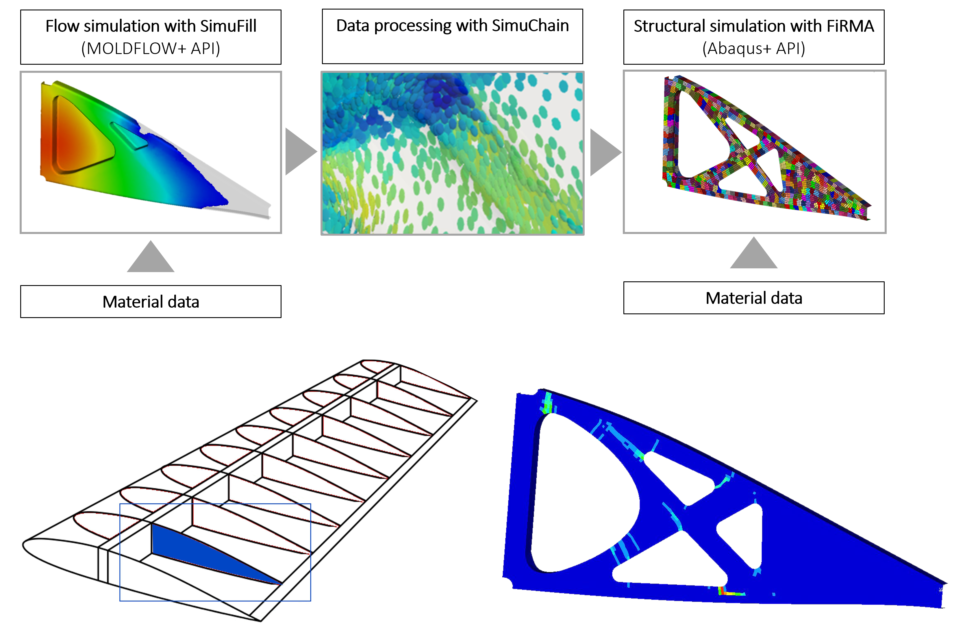
The approach developed by Simutence and Engenuity (Fig. 1) begins with SMC fiber orientation obtained from a high-precision process simulation using SimuFill, an add-on from Simutence for the Autodesk Moldflow software (Autodesk, San Rafael, Calif., U.S.). This information is then processed by SimuChain, also developed by Simutence as a data processing and mapping tool add-on for the Abaqus finite element analysis (FEA) software (Dassault Systèmes, Vélizy-Villacoublay, France).
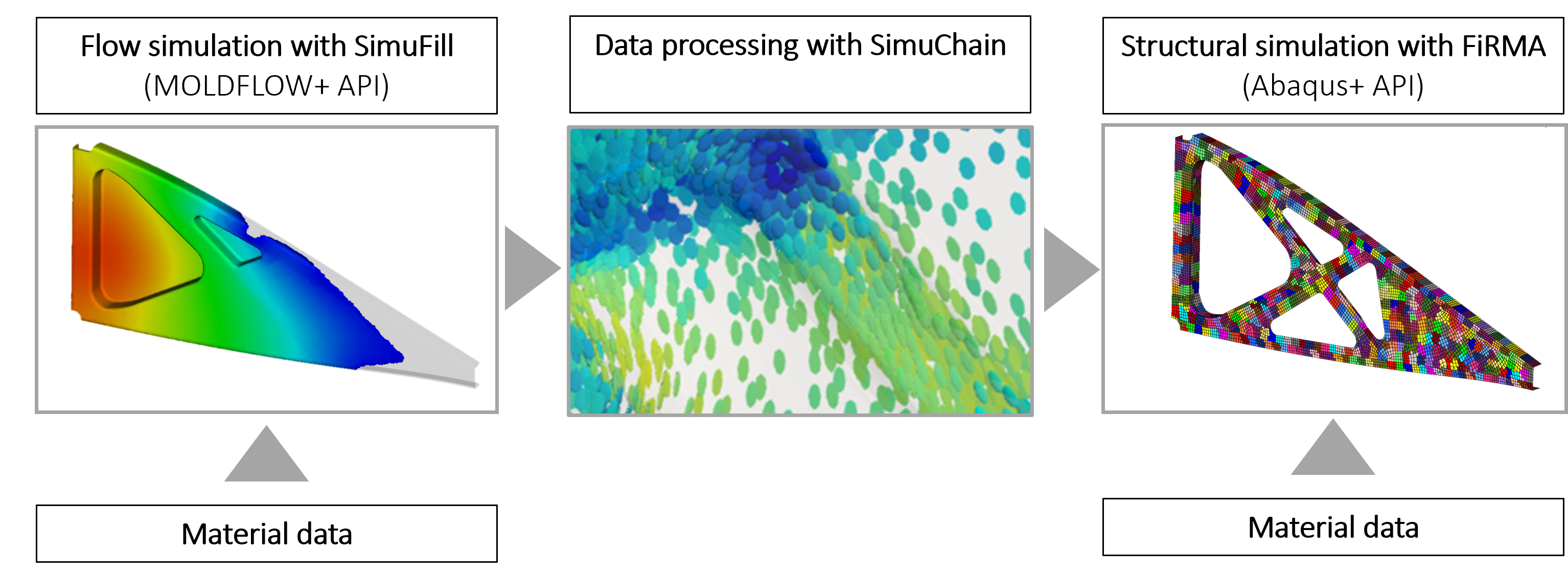
Figure 1. Process chain for new SMC structural simulation approach. Demonstrated for an aircraft wing rib, the simulation steps allow for consideration of short fiber orientation produced during compression molding which is then used for FEA simulation.
After processing, this data is used in Engenuity’s probabilistic approach called Failure in Random Material Architectures (FiRMA) which enables designers to optimize SMC structures by predicting the weakest and strongest components expected in a batch. This is achieved by randomizing the fiber orientations within a distribution provided by the SimuFill flow simulation, and running it multiple times to predict the scattering of mechanical properties seen within a batch of components.
Demonstration project, materials characterization
Spirit AeroSystems (Belfast, U.K.) is a Tier 1 supplier of composite wing components pursuing new materials and manufacturing processes (see CW’s 2023 plant tour). Working with Simutence and Engenuity, Spirit selected a wing rib to demonstrate the FiRMA simulation approach due to the larger production quantity of such parts anticipated for future aircraft. Through the NATEP program, FiRMA has been upgraded to a new version, FiRMA Flow, which includes flow effects during compression molding so that a non-random distribution derived from process simulation is used for structural simulation.
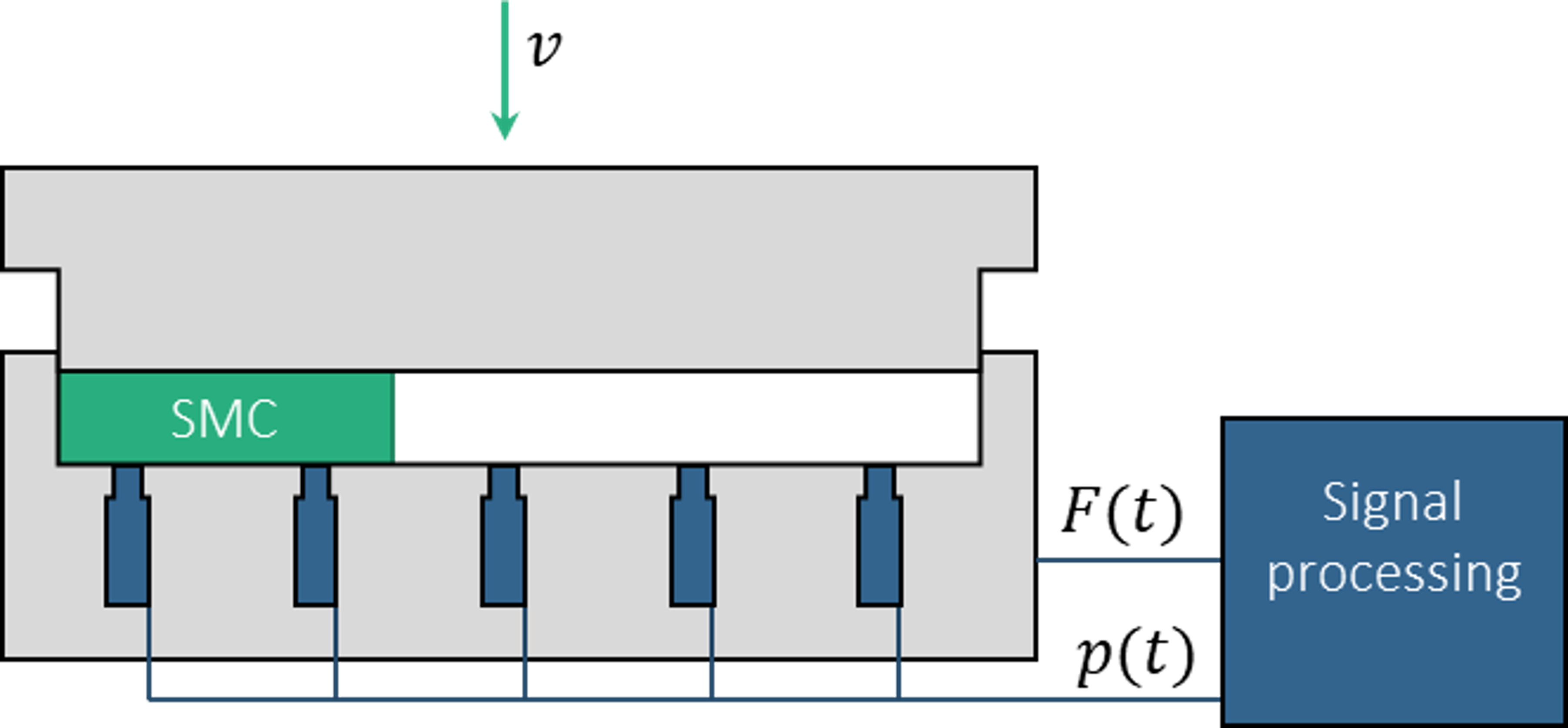
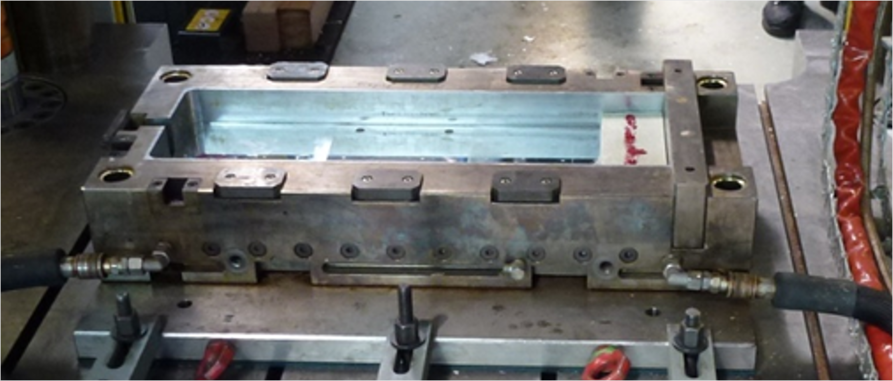
Figure 2. Characterizations of materials for SMC molding. Compression molding trials were used to provide input data/validation for materials characterization in subsequent process simulations.
The demonstrator used Carbkid VK03-5750 from Astar (Sondika, Spain) 57 wt% short carbon fiber in a vinyl ester matrix. To gain all the necessary material data, the material was characterized for the process as well as for the structural simulation. For the process simulation, SimuFill was used with an in-mold characterization method (Fig. 2) to determine the properties of the deformation rate-dominated core region as well as the shear rate-dominated lubrication layer next to the mold. While conducting molding trials with different closing speeds, pressure sensors and press data were used to fit the material parameters to the experimental data with an automated evaluation tool.
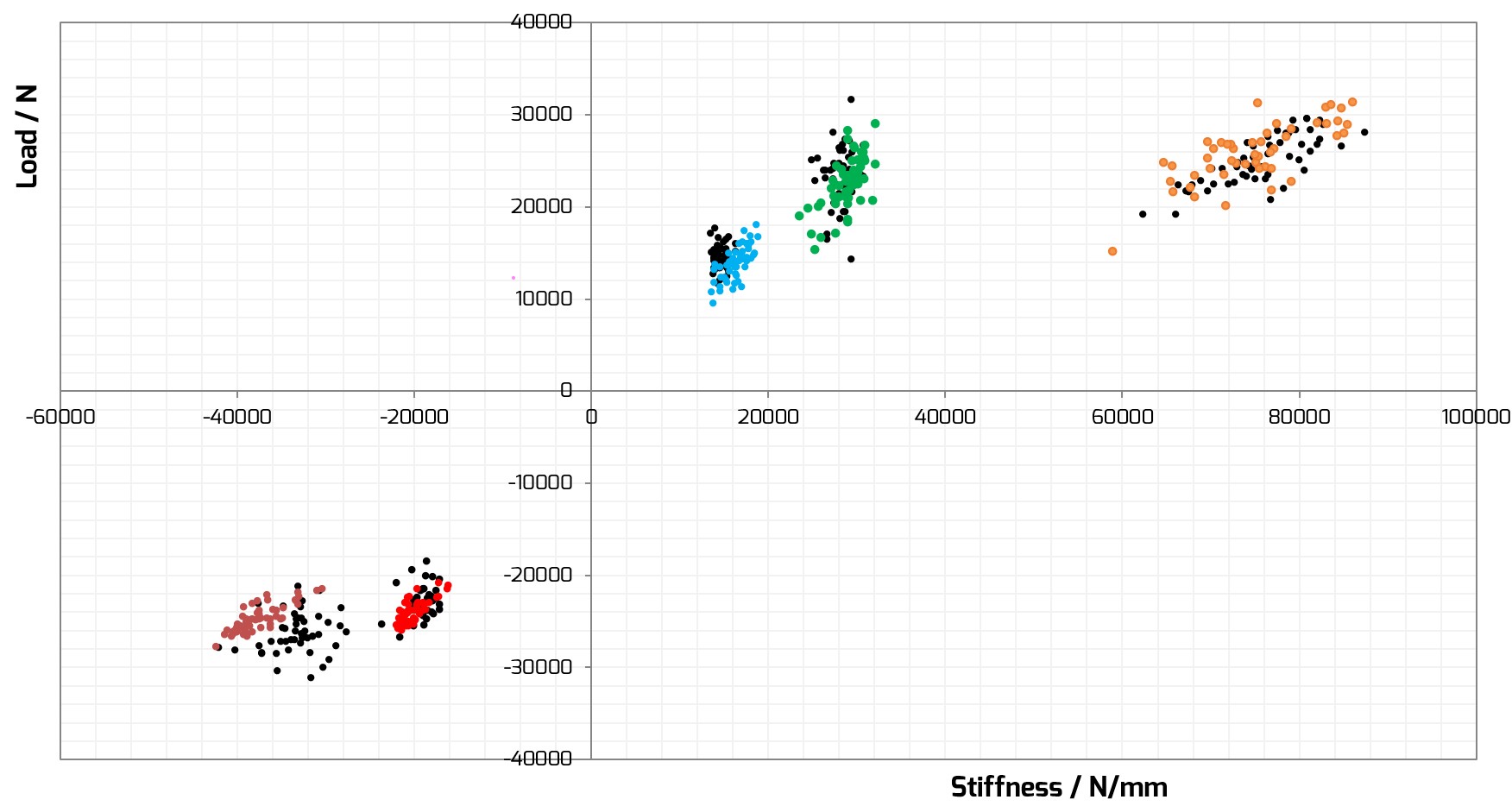
Figure 3. Verification of the material card. This was achieved by comparing the simulation results (colored points) with the experimental trials (black points) for various sample geometries.
For characterization of the mechanical properties, a deterministic material card with stiffness and strength data was created using a specially developed characterization program that employed different coupon geometries and load conditions. This approach aimed to produce a modeling method that is independent of scale and represents the level of load path redundancy that the SMC itself possesses. Through an iterative optimization process, the modeling method can be applied to a component of any scale. A representative verification plot with the different sample geometries for materials testing is shown in Fig. 3.
Defining the design
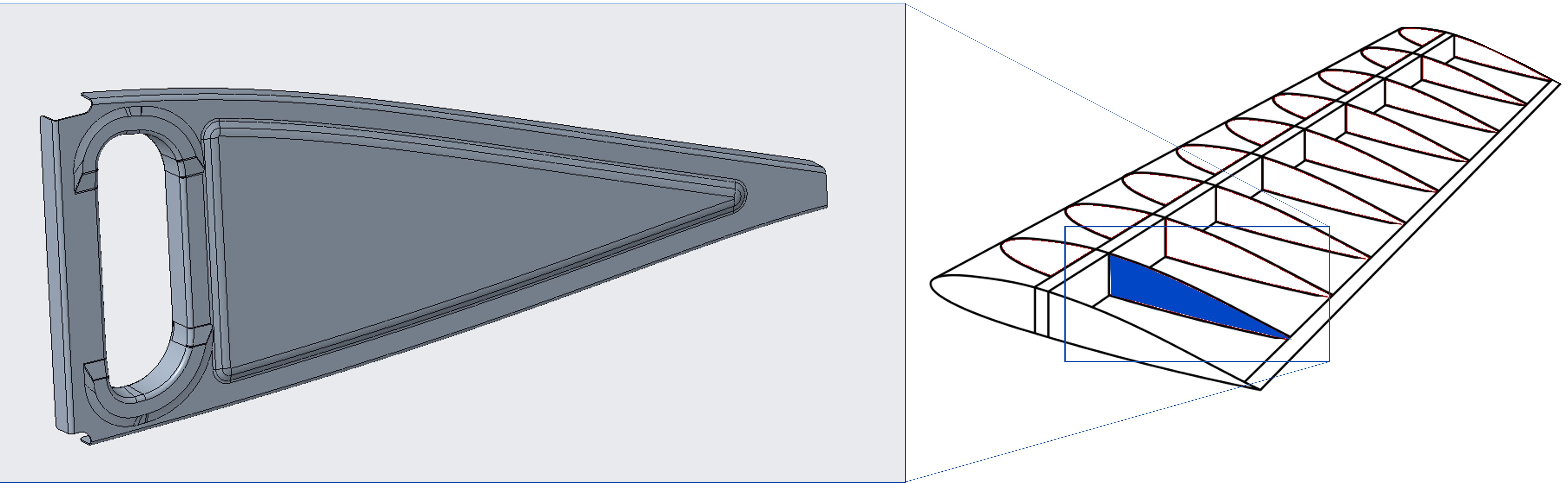
Figure 4. Demonstrator part. The reference wing rib design and position within the wing is shown.
Having generated reliable material cards for the process and structural simulation, the design of the demonstrator wing rib began. Spirit provided the reference geometries and corresponding load cases. Additional boundary conditions included retaining the aperture of the cabling hole/pass-through as well as skin flange and spar dimensions. The most relevant load case was determined to be where the part is fixed on one side while pushed upward on the trailing edge of the wing (Fig. 4). The existing rib design was assessed under a critical buckling load case and provided a benchmark for the SMC rib to target.
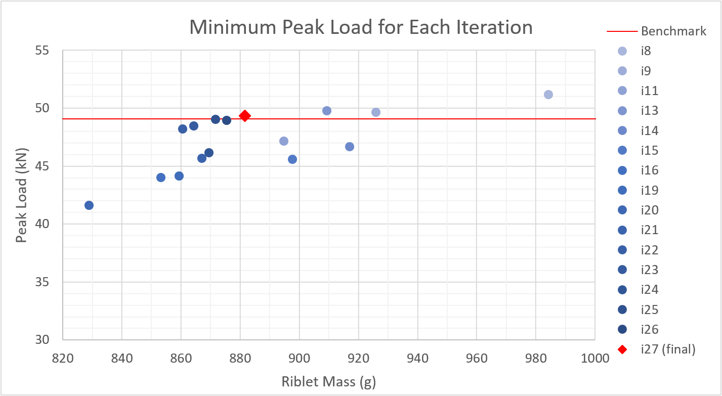
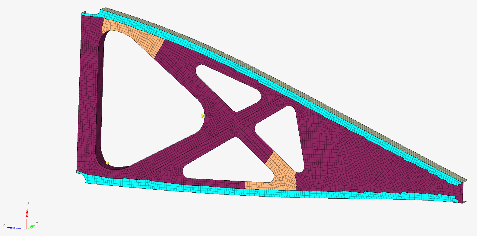
Figure 5. Finalizing the C-SMC wing rib design. Evaluation of the mass and minimum peak load over the design iterations (top) led to the final demonstrator design (bottom).
Starting with the original design, 27 design options were investigated, evaluated and optimized using FiRMA to meet the load conditions while achieving the lightest weight possible. Within these design loops, multiple deterministic structural simulations were conducted, each with modifications to the local fiber orientations, as directed by the process simulation, to represent the degree of randomness within the actual C-SMC. This resulted in a sequence of simulation results, but only the weakest was considered for subsequent evaluations (Fig. 5). This worst case based on fiber orientation scattering ensured a safe design where all parts would indeed meet the load requirements, which is crucial for aerospace applications. This design can then be further optimized (see last section).
Process simulation
For efficiency, the SMC molding process simulation was only conducted for the final wing rib design iteration. To avoid any weld lines within the part, the cabling pass-through/lightweighting holes of this design were created after the molding. Thus, the as-molded part had a closed surface.
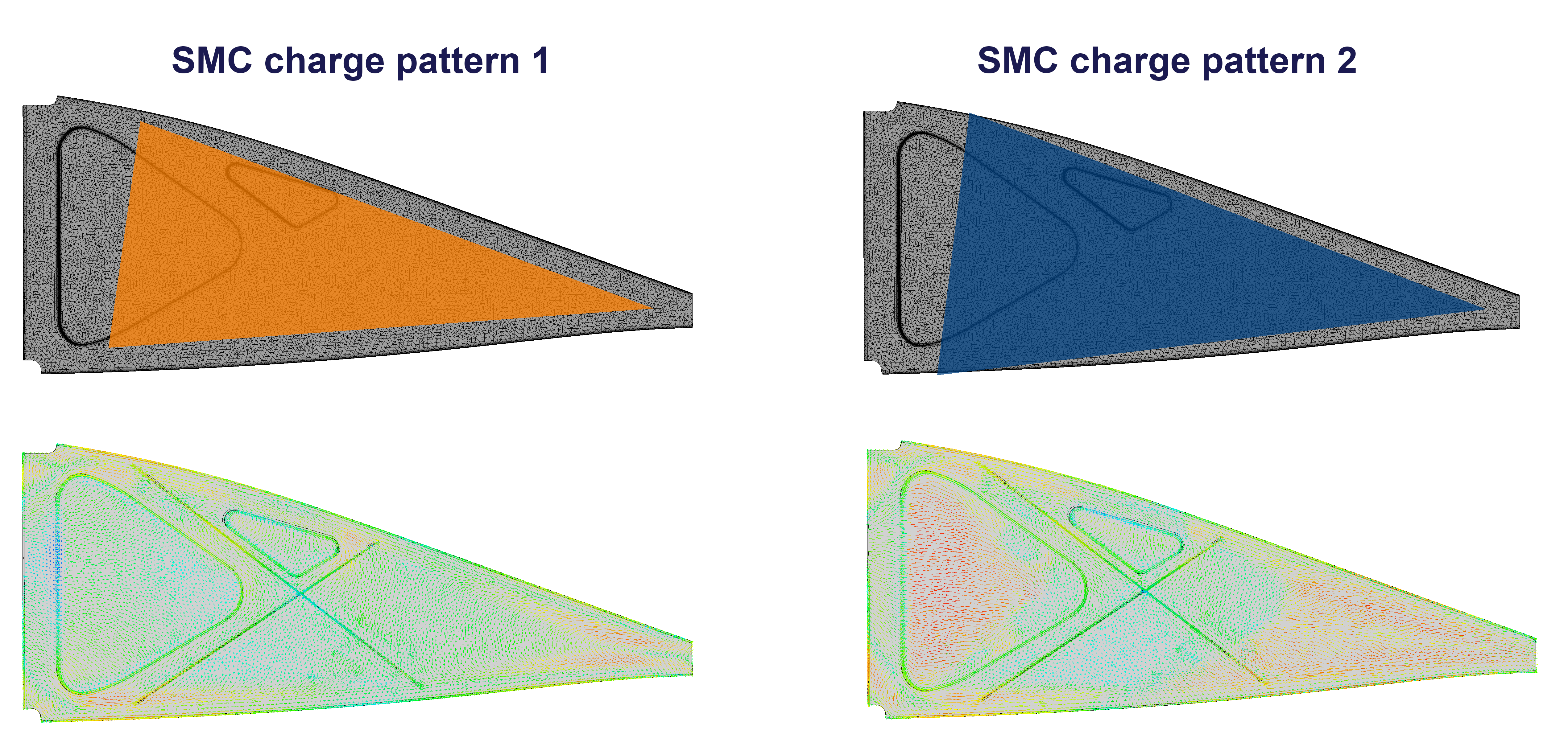
Figure 6. Fiber orientations from charge patterns. The final initial SMC charge patterns used in the molding simulation (top images) resulted in these fiber orientations (bottom images) that were used as an input for Engenuity's FiRMA analysis.
To identify the best initial charge pattern, high usage/low scrap of the C-SMC material as provided on a 1,500-millimeter-wide roll was considered. Two different initial charge patterns were evaluated for the simulations. The process parameters used included a closing speed of 10 millimeters/second and a projected maximum press force of 200 bar. With various optimization loops, the best position of these two initial charge patterns within the cavity was determined to ensure the manufacturability of the part (Fig. 6).
Using the simulation results of these two C-SMC charge configurations, the resulting fiber orientations were exported and processed within a newly developed module of Simutence’s SimuChain software — the second step in the virtual process chain outlined in Fig. 1. The results were then used as input for the new FiRMA Flow workflow using the neutral vtk exchange format.
Final virtual verification
Having the final design, as well as the predicted fiber orientations from two different initial charge patterns available, the FiRMA Flow workflow could be applied. The final FE simulation model from design loop 27 was modified so that the predicted bias of fiber orientation, based on the process simulation results, was used instead of the generic one that had been used in the initial design phase (SMC baseline). By doing this, new populations of probabilistic results were generated, which then helped to further optimize the charge pattern and its position in the mold cavity using simulation of scattered fiber orientations and the resulting mechanical properties.
A conversion of the Spirit AeroSystems model into a C-SMC rib design resulted in the orange population distribution seen in Fig. 7 (top), where the minimum performance fell short of the benchmark target. Using automated feedback tools such as the cumulative damage plot (Fig. 7, bottom) — which highlights all the element failures across the population of 50 analysis runs — enabled the design to be improved to that of the blue population distribution in Fig. 7, where a 28% increase in the minimum predicted failure load (50,000 versus 39,000 newtons) was predicted.
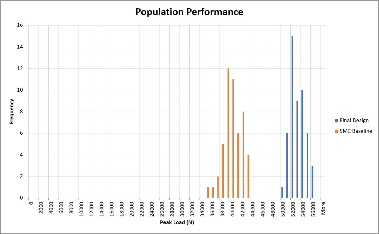
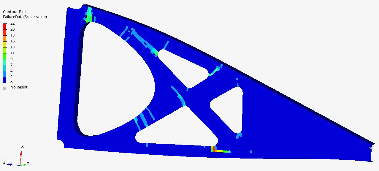
Figure 7. Final simulation results. Using automated feedback tools — such as the cumulative damage plot (bottom) from the 50 analysis runs — enabled the initial C-SMC rib design (orange at top) to be improved (blue at top), with a 28% increase in minimum predicted failure load (50,000 versus 39,000 newtons).
The cumulative damage plot results from all variations in fiber orientations due to the C-SMC design, as directed by the process simulation conducted by Simutence. This plot can help designers to improve the C-SMC design by modifying these areas as necessary.
The approach demonstrated here is not just predicting a single one-off result but a population of results which is more representative than historical analysis approaches — and this should enhance safety factor calculations. This is key, because for aerospace to use C-SMC, the as-manufactured structural part must have a failure load within the required safety margin window.
The approach described here has demonstrated this capability by combining Simutence’s virtual process chain of add-ons for Abaqus FEA software — including thermoforming simulation, filling simulation of SMC press molding and interfaces for mapping onto the as-molded part — with Engenuity’s FiRMA, a unique approach that can identify the weakest part of a population of components. The resulting design optimization iterations enabled prediction of a more accurate safety factor and failure load for a molded C-SMC wing rib demonstrator. This design optimization was completed without any prototype-level tooling required, which speeds development and reduces costs.
The next stage of the project is to manufacture and test multiple ribs to further validate this analysis approach. The project results will be published in 2024 with the aim to demonstrate a step forward to zero prototyping for structural SMC parts, reducing the need for proof testing and the number of iterative trial and error cycles that would typically be used in this type of development.
About the Author

Tim Hall
Tim graduated with a Master’s degree in advanced engineering design in 2010. He started his career working in engineering development in the automotive industry, later switching to aerospace where he has led multiple successful projects implementing novel technology on commercial aircraft. He now leads the commercial team at Engenuity, using material characterization and predictive analysis to develop lightweight and durable structures.
About the Author

Matt Kedgley
After graduating from the University of Bath, having studied aerospace engineering, Matt joined Engenuity in 2011 as a graduate engineer and now works as a senior engineering analyst focusing on the desire to lightweight, optimize and improve structural efficiency within the automotive and aerospace sectors. He is strongly involved in innovative procedures and practices, such as digital image correlation (DIC), composite crash structure analysis and C-SMC analysis methods.
About the Author

Martin Hohberg
Martin graduated from the Karlsruhe Institute of Technology (KIT) in 2013, and later earned his Ph.D. in 2018, with a focus on the process simulation and virtual process chain of SMC. With this experience, Martin and two colleagues received startup funding, which resulted in the founding of Simutence in 2019, where he has since served as managing director. He is involved in innovative simulation and design projects in the automotive and aerospace industries with a focus on compression molding processes and their combinations with continuous fiber reinforcements, as well as in the continuous improvement of the virtual process chain for these processes.


Related Content

Otto Aviation launches Phantom 3500 business jet with all-composite airframe from Leonardo
Promising 60% less fuel burn and 90% less emissions using SAF, the super-laminar flow design with windowless fuselage will be built using RTM in Florida facility with certification slated for 2030.
Read More
Bladder-assisted compression molding derivative produces complex, autoclave-quality automotive parts
HP Composites’ AirPower technology enables high-rate CFRP roof production with 50% energy savings for the Maserati MC20.
Read More
Cutting 100 pounds, certification time for the X-59 nose cone
Swift Engineering used HyperX software to remove 100 pounds from 38-foot graphite/epoxy cored nose cone for X-59 supersonic aircraft.
Read More
Composites end markets: New space (2025)
Composite materials — with their unmatched strength-to-weight ratio, durability in extreme environments and design versatility — are at the heart of innovations in satellites, propulsion systems and lunar exploration vehicles, propelling the space economy toward a $1.8 trillion future.
Read MoreRead Next

Aptera reveals first composite production parts for BinC vehicle
Pre-production efforts are underway to begin building production-intent vehicles.
Read More
Forged molding compound: Extending SMC capabilities
New material, design, process combination approaches prepreg performance with chopped carbon fiber SMC.
Read More
Robotic computed laminography brings X-ray CT resolution to large composite structures
Omni NDE collaborative robots, X-ray end effectors and Voxray’s reconstruction approach enables 5-micron inspection of aerospace parts without size constraints.
Read More