


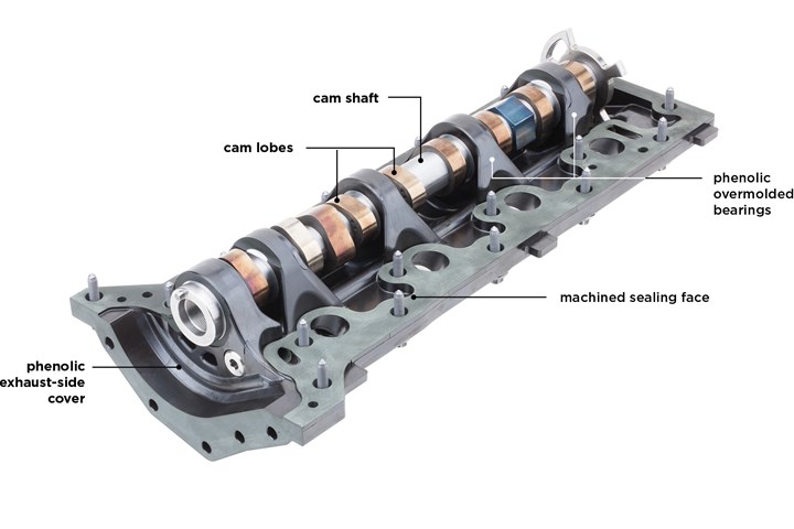
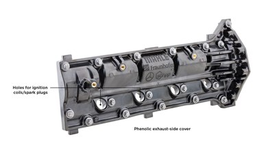
An encouraging three-year research program investigated the viability of replacing aluminum covers on the hot/exhaust side of camshafts with a glass fiber-reinforced phenolic. Not only was the composite cover lighter and quieter, but it incorporated more components, leading to assembly time and cost savings. All photo credit: Fraunhofer Society – Institute for Chemical Technology.
In the race to reduce tailpipe emissions and improve fuel efficiency of passenger vehicles, automakers are exploring alternative powertrain options like electric and fuel cell vehicles. Meanwhile, they’re also working to increase conventional internal combustion engine (ICE) efficiency — for both gasoline and diesel variants — plus trim as much mass as possible from vehicle components. The engine itself is a good lightweighting target since it is still largely steel and aluminum. Recently, a German consortium investigated the viability of converting a metallic camshaft cover to composite, with encouraging results.
Lightweighting opportunities
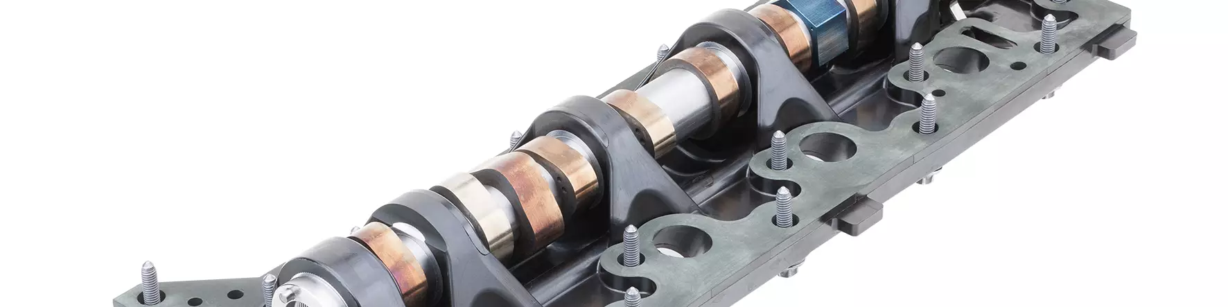
Camshafts are important elements of ICE-powered vehicles. As the shaft rotates, cams (ovoid disks or lobes) push intake valves open/closed in sync with the crankshaft gear. Depending on engine construction, valves feed either air or an air + fuel mixture into pistons where ignition occurs, spinning the crankshaft and propelling the vehicle forward or backward. Typically, camshafts are mounted between split bearings — a shaft bearing made in two pieces that are bolted together and held in cups or bearing blocks — on intake and exhaust sides of either the base of V-engines or between cylinder banks on flat engines. A cover on each side of the camshaft and its bearings protects from water and debris.


The benchmark for the study discussed here was an aluminum camshaft cover on a four-cylinder production gasoline engine with a delta-design cylinder head. The research team focused on replacing the camshaft’s exhaust-side cover, whose proximity to the hot exhaust system makes it the more difficult cover to tackle.
This research was completed under Germany’s “New Vehicle and Systems Technologies” program, funded by the Federal Ministry for Economic Affairs and Energy (BMWi) and administered by transportation consultant TÜV Rheinland (Köln, Germany). The project consortium was led by Tier One Mahle AG (Stuttgart, Germany) and research institute Fraunhofer Society – Institute for Chemical Technology (FhG-ICT, Pfinztal, Germany), plus a German automaker, a composites supplier, and a toolmaker. Mahle was both project coordinator and tier integrator.
Material/process selection
The project began with discussions about materials and processes to meet OEM specs. “Given the rigors of the underhood environment — especially mounted to the engine and incorporating camshaft bearings — we needed a material with excellent mechanical properties to handle high loads at elevated temperatures (up to 180°C) in the presence of engine fluids, so thermoplastics were quickly eliminated in favor of thermosets,” explains Thomas Sorg, FhG-ICT research associate – new drive systems.
“We chose injection molding to demonstrate the application could be used in a large-volume-capable process,” continues Justus Himstedt, Mahle head of camshaft technology. “Injection molding repeatedly produces complex 3D parts in short cycle times and permits insert molding to reduce secondary operations.”
Module underside without the camshaft.
The composites supplier, which made final material selection based on extensive experience, chose a short glass fiber-reinforced phenolic with 55% fiber-weight fraction (FWF). The grade already had OEM approvals for underhood applications and has been long used in water- and oil-pump housings. Phenolics also provide excellent flame, smoke and toxicity (FST) properties and are competitively priced versus vinyl esters. Additionally, the material offers high compressive strength at low density, has nearly zero creep over the projected service life of the camshaft module and its coefficient of thermal expansion (CTE) is similar to that of aluminum, helping reduce thermal stresses during engine operation since, with the exception of the steel camshaft itself, most mating structures were aluminum.
The team carried over sealing areas on the cylinder head and control-housing cover to speed implementation should they be successful. The original metal design was completely reworked, including changing wall thicknesses and redesigning around the cylinder head to ensure the composite module, when mounted, would properly index to the camshaft and hold it tightly to prevent it from flexing as it rotates and controls engine aspiration. As the design evolved, they focused on improving functional requirements (i.e. meeting thermo-mechanical and dimensional requirements, cost targets, assembly efficiency during engine build, etc.).
Detailed CAD models were developed for several design options to assess which produced the best results; next, physical prototypes were 3D printed for further evaluation. Providing most of the project’s simulation work, FhG-ICT used OEM-supplied computer-aided design (CAD) data from similar metal parts and mating surfaces from the benchmark engine. Modeling tools Siemens NX (Plano, Texas, U.S.) and ANSYS (Canonsburg, Penn., U.S.) were used to understand loads and performance requirements. Additionally, the composites supplier conducted mold filling analyses to ensure that tool design, gating, mold inserts/slides and process settings (e.g., temperatures and pressures) were appropriate to mold parts.
“We used simulations to numerically optimize and validate our designs using critical mechanical and thermal loads and boundary conditions from the engine,” explains Dr.-Ing. Lars Fredrik Berg, FhG-ICT deputy head of department – new drive systems. “Maintaining permissible bearing displacement was challenging, since phenolic’s Young’s modulus was lower than that of aluminum. At first it was difficult to meet our targets, but after several design iterations, module stiffness was so improved that bearing displacements remained in the allowable range and local peak stresses were minimized, so we met fatigue targets. While the composite is only one-quarter as stiff as aluminum, our design measures enabled us to meet maximum allowable deformation with a much less stiff material.”
Key design innovations include integration of the lower half of the unsplit-bearing rings into the cylinder head and overmolding of the upper half into the cam cover. While this modular approach required precise positioning of cover to engine — necessitating machining of both cylinder head and module to fit into the groove/notch located on the cam cover to hold the cam down during operation and prevent oil leaks — the composite module permits faster, easier installation, reducing assembly time and total system costs. Post-mold, during machining, the module was held in a stressed state to emulate loads from screw connections joining the module to the cylinder head in order to compensate for any machining-induced deformation.
Once the design was finalized, a single-cavity tool was cut, and the materials supplier molded physical parts on a press capable of delivering shot sizes of 600 cubic centimeters. After demolding, parts were heated to finish crosslinking and achieve higher material properties.
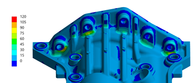
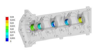
The camshaft module was designed iteratively so local tensile stress maximums at the screw connections met fatigue strength requirements (top). FEA simulations of the module at total deformation of bearing surfaces under critical load also were conducted (bottom).
“In order to fit in a module with closed bearings, all existing bearing blocks (cups) in the cylinder head were machined down,” continues Himstedt. “Also, in the area of the actual bearing points, where loads are greatest, and in the module’s screw connection, geometry was shaped so valve train forces were transmitted in compression.” Composites and their relatively high mechanical properties saved cost and weight by eliminating metallic inserts in areas where screws connected the module to the cylinder head and control-housing cover. Only where fine threads were used (e.g., screw-mount connections for ignition coils and the camshaft sensor), or where the module directly supported the camshaft, were metallic inserts molded into the cover.
Tight tolerance requirements in the cylinder head and cam roller finger followers — used to raise/lower intake and exhaust valves on overhead cam engines — required two-step, post-mold machining of the cover module. First, the sealing area, reference hole, slotted hole and positioning hole for the seal were machined and oil-feeder holes were finished. Second, the bearing seat was machined.
After that, the camshaft and the module were joined via the shrink-fit method to avoid the cover coming loose. Cams, trigger wheel and axial bearing were installed and aligned. Then the assembly was heated to permit the shaft to fit through the cams and be mechanically joined to the cover. The team was careful to prevent excessively heating the composite to avoid degradation. Once the camshaft cooled, bearings were oiled to ensure proper operation. The module installs as a single assembly, saving engine assembly steps and time.
Next, the team measured and documented key aspects of the camshaft to ensure it moved smoothly within the bearing seat. All measured torsional moments were less than 3 newton-meters, a requirement in the unscrewed condition. The cover was optically scanned to check for defects that could cause premature failure — none were found. Next, pull-out tests around exterior-threaded inserts and twist-out and push-out tests on overmolded camshaft bearings were conducted, all with satisfactory results. These tests validated earlier CAE predictions for bearing twist moments of 100 newton-meters, as well as axial push-out forces of ~10 kilo-newtons and mean-pullout forces on threaded inserts of ~5 kilo-newtons.
Subsequently, Mahle validated one prototype on a cylinder-head test bench with portions of the benchmark engine (minus piston train). Twist moments for the camshaft in the module were measured at less than 3 newton-meters in the installed state. After 100 hours, the module was removed and evaluated for defects. Since none were found, and the module was deemed to be operating properly, tests continued for another 500 hours. Deformation analysis via optical 3D measurement before and after showed positive results, as did disassembly of the camshaft from the module to examine wear on bearing points, camshaft contact points and cam/bearing surfaces.
Positive results
Overall, the project demonstrated mass reduction of 20%, noise/vibration/harshness (NVH) improvements, and potential cost savings during engine assembly by eliminating steps normally required to install components like the bearing shells, phaser gear and camshaft position sensor, which are now incorporated into the module. The team feels the project showed composites can be used successfully in demanding ICE applications. Although designed for passenger-car gasoline engines, the concept is translatable to cars or trucks with diesel or gas engines with camshafts and engines positioned similarly to that used in the study.
Further validation in a running engine is planned. Future work could quantify NVH improvements, reduction of greenhouse-gas emissions and optimize mold and manufacturing process to eliminate post-mold machining.


.jpg;maxWidth=300;quality=90;format=webp)

Related Content

Materials & Processes: Resin matrices for composites
The matrix binds the fiber reinforcement, gives the composite component its shape and determines its surface quality. A composite matrix may be a polymer, ceramic, metal or carbon. Here’s a guide to selection.
Read More
Infinite Composites: Type V tanks for space, hydrogen, automotive and more
After a decade of proving its linerless, weight-saving composite tanks with NASA and more than 30 aerospace companies, this CryoSphere pioneer is scaling for growth in commercial space and sustainable transportation on Earth.
Read More
Materials & Processes: Fibers for composites
The structural properties of composite materials are derived primarily from the fiber reinforcement. Fiber types, their manufacture, their uses and the end-market applications in which they find most use are described.
Read More
ASCEND program update: Designing next-gen, high-rate auto and aerospace composites
GKN Aerospace, McLaren Automotive and U.K.-based partners share goals and progress aiming at high-rate, Industry 4.0-enabled, sustainable materials and processes.
Read MoreRead Next

Phenolic Delivers More Torque
German automaker BMW and suppliers collaborate to produce the world's first continuously variable intake manifold.
Read More
Automotive composites: Thermosets for the fast zone
Epoxies continue to be developed for faster cure to meet automotive production rates.
Read More
From the CW Archives: The tale of the thermoplastic cryotank
In 2006, guest columnist Bob Hartunian related the story of his efforts two decades prior, while at McDonnell Douglas, to develop a thermoplastic composite crytank for hydrogen storage. He learned a lot of lessons.
Read More