
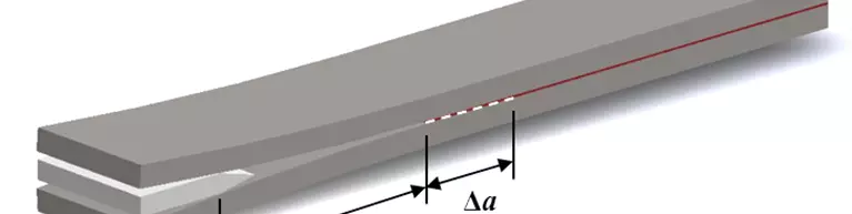


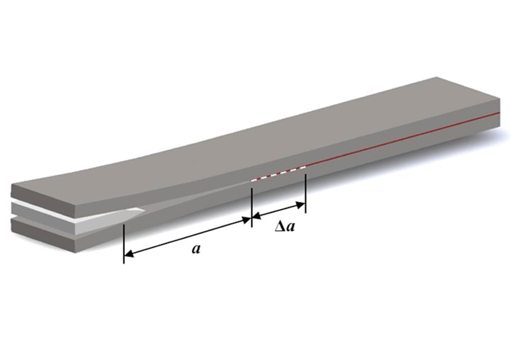
Figure 1. Wedge test specimen configuration. All photo credit: Dan Adams
Three types of coupon-level test methods may be used to assess the performance of bonded joints. Strength-based tests typically involve lap shear specimens, as they best represent the primary loading of typical bonded composite joints. Standardized lap shear test methods have been developed for use with metal, rigid plastic and fiber-reinforced plastic (FRP) adherends. Fracture-based tests used to evaluate bonded composites are based primarily on the existing Mode I double cantilever beam (DCB) test for composite laminates, ASTM D55281. Durability-based tests, also focus primarily on Mode I-type tests, but subject the adhesive-bondline crack tip to high stresses for an extended period of time, ranging from several hours to several days.
Currently, there are no standardized durability-based tests for bonded composites, but test method development is currently underway. In this column, I’ll focus on the development of a durability-based test for adhesively bonded composites commonly referred to as the composite wedge test. This test method is based on the well-established metal wedge test, ASTM D37622, used for durability-based assessment of aluminum-bonded joints.


This test method consists of a 152-millimeter-long and 25-millimeter-wide-bonded aluminum specimen with a 19-millimeter initial disbond length produced in the adhesive bondline at one end of the specimen using a thin separation film. The specimen is loaded by forcing a metal wedge — inserted a fixed distance — between the adherends, causing the initial disbond to propagate from the end of the separation film in the adhesive bondline (Fig. 1). The wedge is retained in the specimen and the initial crack length, a, is measured. Specimens are then exposed to a selected environmental condition, typically high humidity at elevated temperature. After environmental exposure for a specified period of time (ranging from hours to days), specimens are removed from the environmental chamber and the final crack length, a + Δa, is measured. The adherends are forcibly separated and the percent cohesion failure, defined as failure within the adhesive, is estimated within the region of environmental crack growth (Fig. 2). Environmental durability is assessed based on both the length of crack growth during environmental exposure as well as the percent cohesion failure within the region of environmental crack growth3.
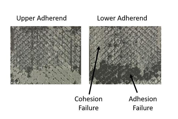
Figure 2. Adhesion and cohesion failures within the region of environmental crack growth.
While hydration of the adherend surfaces is a primary concern associated with the durability of metal-bonded joints4, other sources of durability concerns exist for adhesively bonded composites. Two of the more significant concerns are improper surface preparation and contamination of the bonding surfaces prior to adhesive bonding. Recent research investigations5,6 suggest that a composite wedge test may be well suited for evaluating the long-term durability of bonded composite joints. However, the use of composite adherends produces additional complexities due to their differing flexural rigidity, Ef I, defined as the flexural modulus Ef of the composite adherend multiplied by its area moment of inertia I. For composite adherends, variations in Ef I may result from differences in composite materials, volume fractions, ply thicknesses, number of plies and laminate ply orientations. Differences in Ef I between sets of specimens will result in differences in both the initial crack length and the length of crack growth during environmental exposure, preventing the use of crack length in durability assessment.
An important advancement in the development of the composite wedge test was the transition from using environmental crack growth as a measure of durability to the use of an estimated fracture toughness, GC. Using beam theory, GC from a composite wedge test specimen may be determined using the equation
where Ef is the flexural modulus of the adherend material, t is the thickness of the wedge, h is the thickness of the composite adherend and a is the crack length. A correction factor to the beam theory expression for GC (in parentheses above) was identified to account for the rotation of the adherends at the plane of the crack tip7. Using this equation, an estimate of the fracture toughness following environmental exposure may be obtained from the composite wedge test by measuring the final crack length. Additionally, an estimate of the fracture toughness of the adhesive bondline at room temperature/ambient conditions may be obtained by using the crack length prior to environmental exposure in the above equation.
Note that the use of the above equation requires that the adherend flexural stiffness Ef and thickness t must be measured. An alternative approach is to write the above equation for GC in terms of the flexural rigidity Ef I producing
where b is the specimen width. In-situ measurements of the flexural rigidity, Ef I, may be obtained using representative wedge test specimens subjected to DCB-type loading following wedge testing. The slope of the load versus deflection curve, ∆P/∆δ, corresponding to the measured final crack length a, is used to calculate the flexural rigidity, Ef I, using the equation
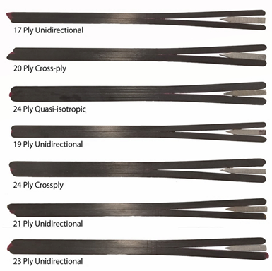
Figure 3. Composite wedge test specimens of varying adherend thicknesses and laminate ply orientations.
Using this methodology, GC values obtained from adhesively bonded, carbon fiber/epoxy composite wedge test specimens were found to be relatively constant across adherend thicknesses and laminate ply orientations producing Ef I values that vary by 250% (Fig. 3). These results suggest that wedge testing may be performed using composite specimens with differing adherend flexural rigidities and the results compared directly.
In summary, the composite wedge test appears to be a well-suited test method for evaluating the durability of bonded composite materials. As with the ASTM D3762 metal wedge test, the procedure is simple to perform and multiple specimens can be tested concurrently without the use of mechanical testing equipment. The development of a standardized test method for the composite wedge test is currently in its initial stages. For additional information, please contact me at dan@wyomingtestfixtures.com.
References
1ASTM D5528-13, “Standard Test Method for Mode I Interlaminar Fracture Toughness of Unidirectional Fiber-Reinforced Polymer Matrix Composites,” ASTM International (W. Conshohocken, PA, US), 2013 (first issued in 1994).
2ASTM D3762-03(2010), “Standard Test Method for Adhesive-Bonded Surface Durability of Aluminum (Wedge Test),” ASTM International (W. Conshohocken, PA, US), 2010 (revision in progress).
3Child, C.L., Adams, D.O., and DeVries, K.L., "Wedge Test Method Improvements for Assessing the Durability of Adhesively Bonded Joints," proceedings of SAMPE 2013, Long Beach, CA, May 6-9, 2013.
4Davis, M.J., and McGregor, A. “Assessing Adhesive Bond Failures: Mixed-Mode Bond Failures Explained,” ISASI Australian Safety Seminar, Canberra, 4-6 June 2010.
5Bardis, J. D. and Kedward, K. T., “Effects of Surface Preparation on the Long-Term Durability of Adhesively Bonded Composite Joints,” FAA Technical Report DOT/FAA/AR-03/53, January 2004.
6McCartin H.M., Ricsi, D.M., Brown, N.C., Adams, D.O., and Devries, K.L., “Environmental Durability Assessment of Composite Bonded Joints Using the Wedge Test,” CAMX 2016, Anaheim, CA, September 26-29, 2016.
7Creton, C., Kramer, E.J., Chung, Y.H., and Brown, H.R., “Failure Mechanisms of Polymer Interfaces Reinforced with Block Copolymers,” Macromolecules, Vol. 25, 1992, pp. 3075-3088.


Related Content

Multi-scale 3D CT imaging enables digital twinning, high-fidelity simulation of composite structures
Computed tomography (CT) provides highly accurate 3D analysis of internal microstructure, performance simulation of carbon fiber/PEEK satellite strut.
Read More
Crashworthiness testing of composites: A building block approach, Part 1
Determining the crashworthiness of composite structures requires several levels of testing and analysis, starting with coupon-level crush testing.
Read More
Development of fracture mechanics test methods for sandwich composites: An update
An update on the CMH-17 Sandwich Disbond Working Group’s sandwich SCB test and two additional sandwich composite fracture mechanics test methods under development.
Read More
Modular approach to material card development of composites
Forward Engineering GmbH walks through a modular testing and simulation approach for automotive/aviation composites enabling more accurate material selection earlier in the design phase.
Read MoreRead Next

Troubleshooting failures in adhesive-bonded composite joints
Cause of adhesive bonding inconsistencies or failure may be numerous. According to Louis Dorworth, the following points should be examined to determine the culprit.
Read More
Thermoplastic composite materials and processing interactions
Selection of product material formats and their interactions with various process methods heavily influence a final TPC part’s properties and fabrication options.
Read More
Composite trends gaining industrial traction for 2026
Startups & Investors topics over the last year show the industry is rapidly gaining maturity while benefiting from macro-trends in circularity, AI and TPC and high-rate manufacturing, all potential gains for investors.
Read More