


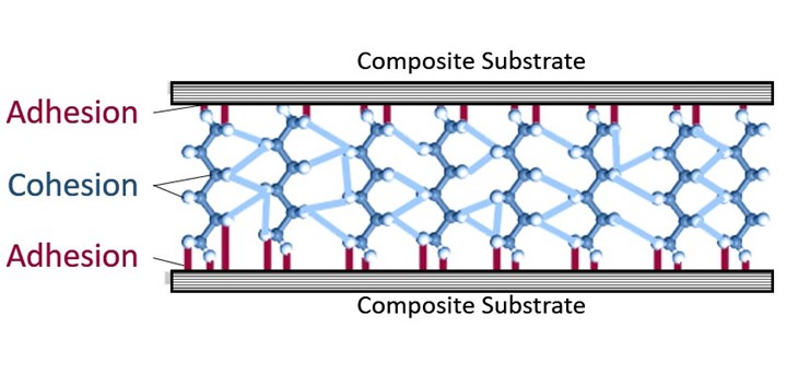
Figure 1. Adhesion failure occurs at the interfacial region between the adhesive and substrate, while cohesion failure occurs within the adhesive layer itself. Photo Credit: Abaris Training
When experiencing inconsistencies with adhesive bonding in production, prototyping or in the lab, how does one identify the root cause and which course of corrective action to deploy to fix it? This month, I will share some generic ideas that may be helpful to your efforts.
First, let’s explore the adhesive bonding mechanism itself. Fundamentally, there are three regions in the adhesive-bonded joint (ABJ) that can fail: adhesion to the substrate; cohesion of the adhesive itself; and the (first ply of) substrate adjacent to the adhesive. For this discussion, we will focus on adhesion and cohesion failures (Fig. 1).


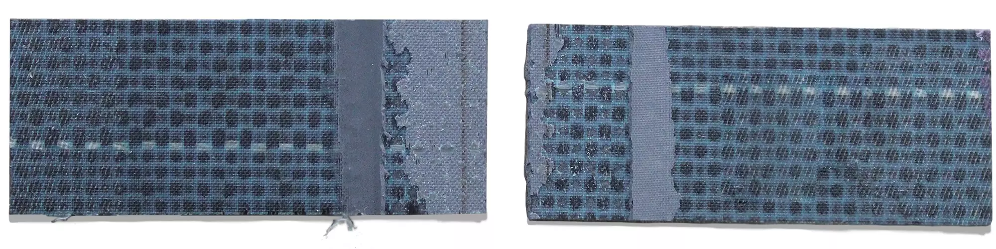
Adhesion failure occurs when the adhesive fails to robustly attach to the substrate, appearing as if the adhesive separated clean from the surface (Fig. 2). It should be noted that adhesion takes place in a very delicate region on the surface, two to three molecules thick (a fingerprint is ~1000 molecules thick).
Here are some possible reasons for adhesion failure:
- Moisture or contamination present on the substrate surface from improper storage and/or handling of the part and/or adhesive, or other environmental exposure of surfaces during the manufacturing process.
- Migration of fugitive oligomers from the mold release to the part surface during molding operation; this is often difficult to remove prior to surface preparation/treatment.
- Poor or inadequate surface preparation or treatment — over or under abrading, or other preparation leading to a low surface free energy value of the substrate surface.
- Excessive open-time (not work-life) of applied paste adhesive prior to closing the joint — possible carbonation of the adhesive surface (amine exposure to CO2).
- Improper selection of adhesive with poor wetting ability — high surface tension value of the adhesive or chemically attractive fillers that keep the adhesive bound to itself.
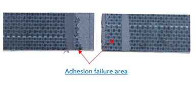
The adhesive failed to stay attached to primarily one substrate but also a small area at the edge of the mating substrate. Photo Credit: Abaris Training
Cohesion failure occurs when the adhesive itself fractures or splits and there is still adhesive attached to each substrate. This is normally acceptable at a predictable load; however, it is unacceptable when failure occurs at much less than expected force (Fig. 3).
Possible reasons for the latter include:
- Ingress of moisture into film adhesive or carbon dioxide infiltration into one or both components of a paste adhesive (usually in the amine hardener).
- Migration of contaminants from substrate surface(s) into the adhesive, changing adhesive properties.
- Improper mix ratio or mixing of two-part paste adhesives, changing adhesive properties.
- Excessive voids in adhesive from the effect of vacuum during processing or incorrect selection of bondline thickness control media.
- Inadequate cure of adhesive — poor control or measurement of temperature at the bondline.
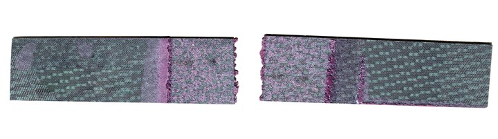
The adhesive itself fractured down the middle leaving equal amounts of adhesive on each substrate. Photo Credit: Abaris Training
After the surfaces of the ABJ failure are observed for causation, the findings then guide you where to look for problems. A close examination of each critical control point in the manufacturing process will help you determine where contamination might occur, or where bond quality might be compromised. This can be accomplished by systematically verifying each step in the process. Below are some critical points to follow.
Storage and handling
Adhesives should be stored correctly at recommended temperatures and properly sealed. Examine handling and dispensing protocols to ensure that materials are adequately thawed to room temperature, that environmental exposure is minimized or mitigated, that out-time is monitored (films), and that paste adhesive containers are resealed (preferably purged with inert gas) immediately after dispensing. Parts should be kept clean, dry and protected from moisture ingress and UV exposure prior to preparation and bonding. Clean gloves should be worn — no bonding surfaces should be touched, including the adhesive itself.
Cleaning
Review cleaning practices. Fresh wipes and solvents (if applicable) should be clean and stored properly to prevent ingress of moisture and other contaminants— often solvents are dispensed via small, approved containers (no plunger cans or open dispensers). A contact angle (CA) measurement test can be used to verify cleanliness (Fig. 4) before and after surface preparation.
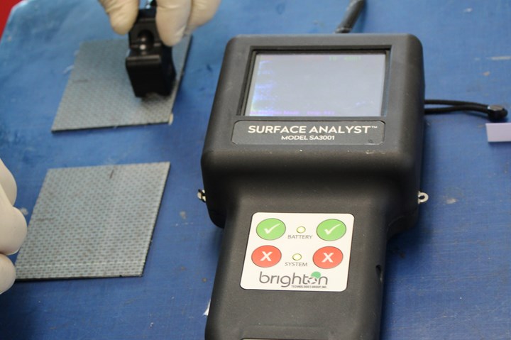
Contact angle measurement on carbon fiber-reinforced polymer (CFRP) panels prior to bonding. Photo Credit: Abaris Training, BTG Labs
Surface preparation/treatment
The goal is to raise the surface free energy of the surface without damaging fibers. Ideally, bond surfaces should be protected with a wet peel ply (WPP), preventing contamination and providing a bondable surface. All abrasives should be surfactant-free and the abrasion process should not damage fibers. For flame or plasma treatments, verify air pressure or gas type, standoff distance, rate, etc. Verification should be performed with CA measurements, not water-break methods (avoid hydration of the surfaces). Parts should be bonded within minutes to hours after prep.
Bonding
Verify that fixtures or clamping devices are clean and undamaged. Check accuracy of measuring and mixing procedures for paste adhesives and that it is applied immediately after mixing. Film adhesives should be cut and applied without touching or contaminating bond surfaces, handling only the edges with gloved hands. Joints should be closed and clamped within a specified time, with uniform pressure applied.
Adhesive cure
Confirm that adhesive within the joint sees time at temperature. Mistakes are made when adhesive is not heated at an appropriate rate or held at temperature for a specified time. Note that most adhesive manufacturers specify room temperature (RT) as 77°F (25°C). If the temperature in the facility is lower, the prescribed time must be extended. Optionally, an elevated cure can be employed.
Identifying inconsistencies
There may be more operations in your manufacturing scheme that need examination. The idea is to perform systematic evaluations of each step in the process and mitigate any pre-bond contamination or other causes affecting the bond integrity. Though all of these factors may seem complex, putting control-point protocols in place makes it possible to routinely achieve high-quality adhesive bonded joints and speeds identification of the cause when bonding issues do arise.
About the Author

Louis C. Dorworth
Louis Dorworth is the direct services manager at Abaris Training Resources, Inc. (Reno, Nev., U.S.). Lou has been involved in the composites industry since 1978 and has experience in material and process (M&P) engineering, research and development (R&D), tooling, manufacturing engineering, teaching and troubleshooting. Lou is a coauthor of the textbook titled Essentials of Advanced Composite Fabrication and Damage Repair, second edition.


.jpg;maxWidth=300;quality=90;format=webp)


Related Content

Manufacturing the MFFD thermoplastic composite fuselage
Demonstrator’s upper, lower shells and assembly prove materials and new processes for lighter, cheaper and more sustainable high-rate future aircraft.
Read More
PEEK vs. PEKK vs. PAEK and continuous compression molding
Suppliers of thermoplastics and carbon fiber chime in regarding PEEK vs. PEKK, and now PAEK, as well as in-situ consolidation — the supply chain for thermoplastic tape composites continues to evolve.
Read More
A new era for ceramic matrix composites
CMC is expanding, with new fiber production in Europe, faster processes and higher temperature materials enabling applications for industry, hypersonics and New Space.
Read More
Plant tour: Spirit AeroSystems, Belfast, Northern Ireland, U.K.
Purpose-built facility employs resin transfer infusion (RTI) and assembly technology to manufacture today’s composite A220 wings, and prepares for future new programs and production ramp-ups.
Read MoreRead Next

Surface treatment for adhesive bonding: Thermoset vs. thermoplastic composites
According to BTG Labs, common surface treatment methods like abrasion and plasma treatment work best for different materials.
Read More
From the CW Archives: The tale of the thermoplastic cryotank
In 2006, guest columnist Bob Hartunian related the story of his efforts two decades prior, while at McDonnell Douglas, to develop a thermoplastic composite crytank for hydrogen storage. He learned a lot of lessons.
Read More