

.jpg;width=70;height=70;mode=crop;format=webp)


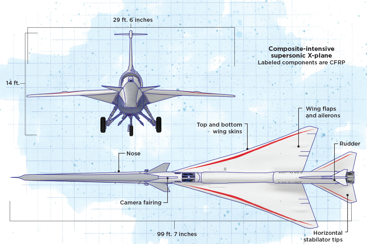
Image illustrated by Susan Kraus.
Commercial supersonic air travel promises the transport of passengers or cargo up to twice as quickly as today’s flights. However, one of the largest hurdles has always been the thunder-like sonic boom that results from the displacement of air at high pressures around a plane that is traveling faster than the speed of sound. Because of this noise disruption, since 1973, the U.S. Federal Aviation Administration (FAA) has banned overland civil aircraft flying faster than Mach 1, the speed of sound.
With its Low-Boom Flight Demonstration project, NASA (Washington, D.C., U.S.) aims to pave the way for overland commercial supersonic air travel, by developing an experimental X-plane designed to drastically reduce the noise level of sonic booms. This plane, called the X-59 Quiet SuperSonic Technology (QueSST) aircraft, will be flown over select cities in the U.S., where NASA will conduct community response studies to capture data on sound levels and community reaction. The goal is for this data to help inform regulators like the FAA as it creates new acceptable noise standards to enable overland commercial travel in the near future.


Almost ready for its first flight tests later this year, the X-59 is a piloted, experimental aircraft developed with partner Lockheed Martin Skunk Works (Palmdale, Calif., U.S.). It is expected to travel up to Mach 1.4 (about 1,074 miles per hour) while reducing the sonic boom to what NASA calls a sonic “thump,” accomplished primarily through the aircraft's unique shape. The X-59’s long, narrow nose and delta-shaped wings built from carbon fiber-reinforced composites are designed to spread out supersonic shockwaves, which reduces the sound heard on the ground. The engine is also placed above the wings to further reduce noise.
The design process: Requirements and multi-team digital design
Lockheed Martin’s Skunk Works facility is known for developing innovative one-off and prototype planes, including several previous X-planes for NASA. Gene Folsom, senior aeronautical engineer on the X-59 at Lockheed Martin Skunk Works, says, “Building one-offs and prototypes and X-planes, that’s our legacy. We’ve been doing this for a long time, and the culture that we have here enables us as engineers to have a broad understanding; we’re all adept at working on parts ourselves. We all have cuts on our hands and resin under our fingernails, every one of us.”
The company’s work on the X-59 began in 2013, after Lockheed won the NASA contract for the project. A variety of aerodynamic, mechanical and other requirements were set by NASA — altitude the plane needed to reach, time in the air, maneuvering capabilities and so on — but the driving factor for every design choice was the need for a sonic boom signature of less than 75 decibels, or about the loudness of a car door slamming. According to NASA, typical sonic booms can exceed 110 decibels, about the loudness of a thunderclap.
Enabling commercial supersonic air travel. The purpose of the X-59 is to validate that it is possible to build a supersonic aircraft that achieves acceptable sonic boom levels for overland travel. NASA hopes that flight and perception tests with the X-59 will enable new regulations allowing for overland supersonic air travel, and that the X-59’s design will help inform future commercial aircraft design. Photo Credit: Lockheed Martin
David Richardson, program director for the X-59 at Lockheed Martin Skunk Works, explains that Lockheed was the best fit, in part, because of a predictive code that his team had developed to virtually generate the optimum shape of the aircraft for the required sonic boom level. “We can actually control and virtually predict the loudness of the sonic boom,” he says.
Dr. Michael Buonanno, X-59 air vehicle lead at Lockheed Martin Skunk Works, explains the design approach: “We looked at different ways to build the X-59, not only including different materials, but also the types of parts themselves. We looked at how fast the aircraft should be able to go, and even, for a brief time, it was being considered whether or not the X-59 should be piloted or be an uncrewed airplane.” The aircraft was ultimately designed for a pilot, to ensure better and faster on-the-spot decision making when the aircraft undergoes its mission of supersonic flight and is flying above the continental U.S. Buonanno notes that while the X-59 will fly at Mach 1.4, which is the limit of the plane’s GE F414 engine, future target speeds for low-boom airliners are Mach 1.6.
Folsom adds that unlike commercial passenger aircraft, stiffness was the key mechanical requirement to the design. “Most airplanes — fighter jets, cargo jets — they’re designed to be very strong and to carry lots of payload. Well, with the X-59 you don’t have that. This is actually a stiffness-driven design not a strength-driven design, meaning we’re extremely sensitive to any deflections of the wing or the nose or any of the control surfaces while we’re flying along — if we hit a bump in turbulence or if we go around a corner intentionally or what have you.” Richardson adds that because only one X-59 would ever be built, the team had to overdesign to the mechanical requirements to eliminate any chances for error and ensure the aircraft can meet all load requirements during the life of the airframe.
To optimize the aircraft design, many teams at Lockheed Martin Skunk Works cooperated over a period of seven months: aerodynamics, sonic boom specialists, loads, stress, design. Folsom describes the back-and-forth process as a sort of balancing, requiring compromise and much tweaking in the ply schedule and part geometry to achieve proper global stiffness and tailored flexibility where needed, aerodynamics and strength, all with the goal of producing the most efficient airplane with the lowest sonic boom possible.
During this process, various design software tools were used by each of these teams, working together in “a closed-loop cycle,” Folsom says. This included aerodynamics and model-based design software, such as Dassault Systemes’ (Vélizy-Villacoublay, France) CATIA for design and manufacturing planning. Dassault’s Abaqus, MSC Software’s (Newport Beach, Calif., U.S.) NASTRAN and several in-house tools were all used to analyze the models. On the floor, manufacture and assembly were informed by real-time drawings via Dassault’s Composer on handheld tablets.
The NASA team has been integral to the entire design process as well, providing requirements, helping with design analysis in the beginning and systems testing now. NASA also provided several systems on the aircraft directly, such as the external vision system and — as is common with X-planes — re-used components from defense vehicles, including landing gear and actuators from retired F-16s or F-18s.
X-59 QueSST: Materials, structures
Described on Lockheed Martin’s website as “resembling a futuristic paper airplane,” the X-59 comprises a 99.7-foot-long airframe featuring a 34-foot-long cantilevered nose, a 29.6-foot single-piece delta wing, a cockpit with no forward-facing window and engine and air duct placement above the wing to further muffle sound. The overall appearance is designed to “reshape” or spread out the displaced air — shock waves — that occur during flight of the aircraft, resulting in quieter sonic booms.
Materials were evaluated early in the design process — the Lockheed team determined that because it is a one-off aircraft, only highly mature material systems and technologies would be used. “There’s no new material science technology at all used on the X-59, and all of the materials, whether metallic or composite, have prior heritage within Skunk Works,” Richardson says. “The objective was not to pioneer any manufacturing or material technologies — it was really built to generate a sound from the aircraft [to meet NASA’s requirements].”
According to Buonanno, the resulting design is more metal-centric on the tail and back half of the plane, including the fuselage, with more composites used on the wing, and in the front half of the plane including the nose. This choice of materials was driven by thermal requirements in the engine bay as well as the weight-critical nature of the front part of the aircraft, Buonanno explains. Given the length and narrowness of the nose compared to traditional commercial aircraft, he notes, “The airplane is very unusual because it’s nose-heavy rather than tail-heavy, meaning we needed to reduce the weight of the nose as much as possible.”
Designing the nose. The carbon fiber composite nose comprises a left and right half that are bonded and fastened together. It was designed for overlapping material on the top and bottom seams to add stiffness to prevent bending of the nose during flight. Photo Credit: Lockheed Martin
In the final design, composites were used to manufacture the nose and chines; top and bottom wing skins; flaps, rudder and ailerons; T-tail trailing edges on the top of the aircraft; tips on the stabilator, which is the horizontal tail in the back; the dome over the XVS camera; and the inlet duct. By weight, the composite components make up about 2,050 pounds (22%) of the 9,500-pound empty airframe. The most prevalent composite material chosen for these components is Solvay’s (Brussels, Belgium) MTM-45 carbon fiber/epoxy prepreg, which was originally developed to enable out-of-autoclave (OOA) cure.
Richardson notes, “If you were to go to an operational airliner in the future, say 10 years from now, I believe you’d see a very different range of materials.” For a commercial vehicle, light weight — leading to longer range and/or higher payload capacity — would be even more important, opening the door for more potential composites use, he says.
Wings: In-house, automated fiber placement (AFP)
Putting subsystems above the wing on the X-59 “drove the sound, but that wasn’t what drove us to composites as opposed to metallics on the wing system,” Folsom says. The wing skins, on closer inspection, are far from flat surfaces — “every square inch is different than the square inch around them, the loft is continuously changing” — which would make metallics like stretch-formed aluminum complex and costly to work with. “You need composites in the wing to do the complexity of that curve. Metallics were never even considered,” he says. Composites also allowed the team to tailor the stiffness in different directions. “You can tailor it just by changing the ply laminates — you can’t do that with metals,” Folsom notes.
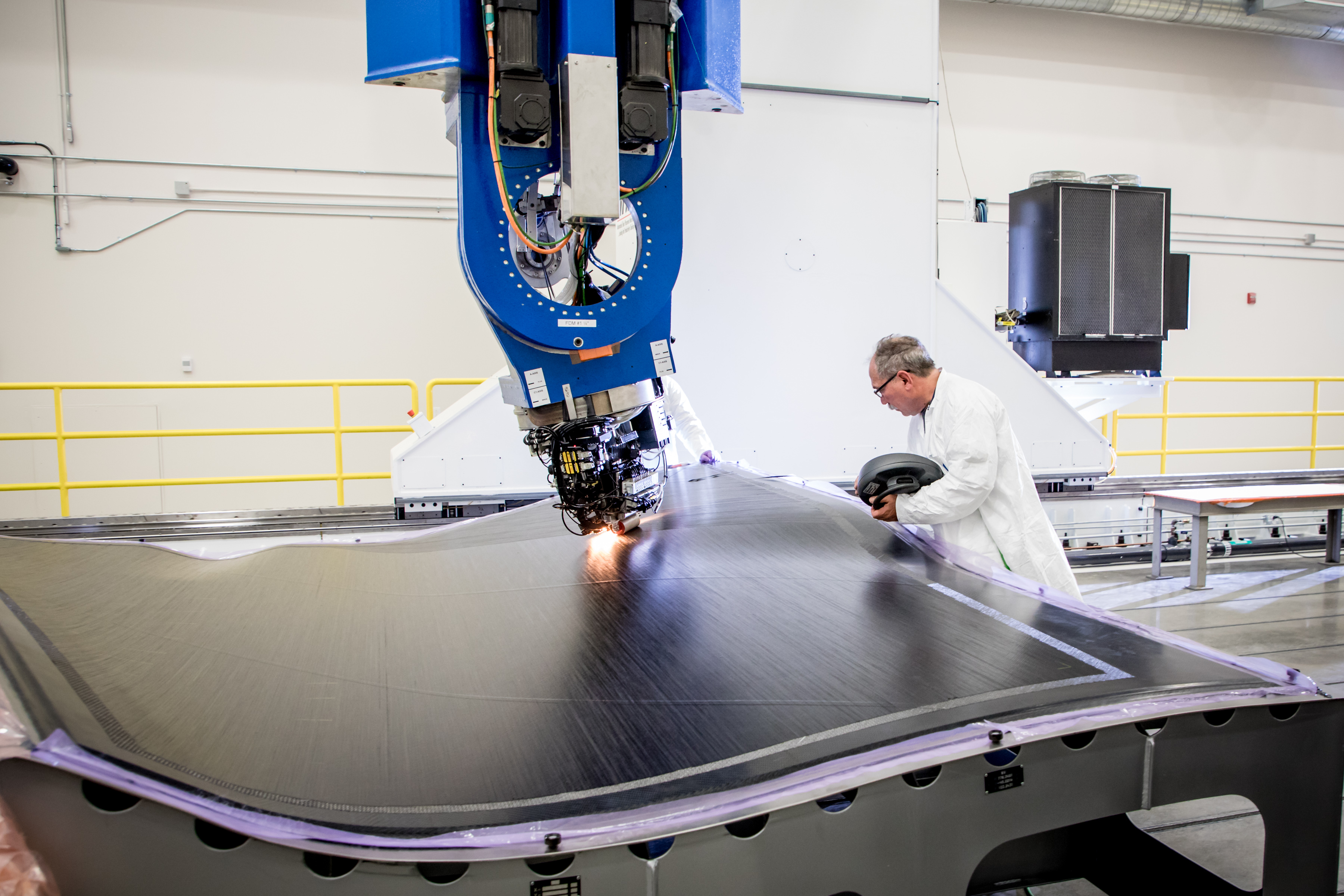
In-house wing manufacture. The composite wing skins were built by Lockheed Martin using the company’s Ingersoll AFP system and oven cure. Photo Credit: Lockheed Martin
The top and bottom wing skins are manufactured as 0.2-inch-thick solid laminates, from MTM-45 4-inch-wide unidirectional (UD) tapes laid up using Lockheed’s in-house Mongoose automated fiber placement (AFP) machine supplied by Ingersoll Machine Tools (Rockford, Ill., U.S.). “It’s one of the largest AFPs in the world,” Folsom says. “We can do a laminate the size of a room without even batting an eye.” This five-axis, gantry-style AFP system uses a localized infrared heater to temporarily increase the tackiness to improve the layering of each tape and hold them in place during AFP. This is followed by oven cure.
The lower wing skin is one continuous structure, minus a few holes for the landing gear, while the upper skin is manufactured as two separate pieces that sit on either side of a 34-inch metallic skin section in the middle. “That’s so we have places for the access panels, for the fuel pumps and whatnot inside the tanks, as well as it’s just a safe, easy place for maintenance crews to be able to walk on,” Folsom explains.
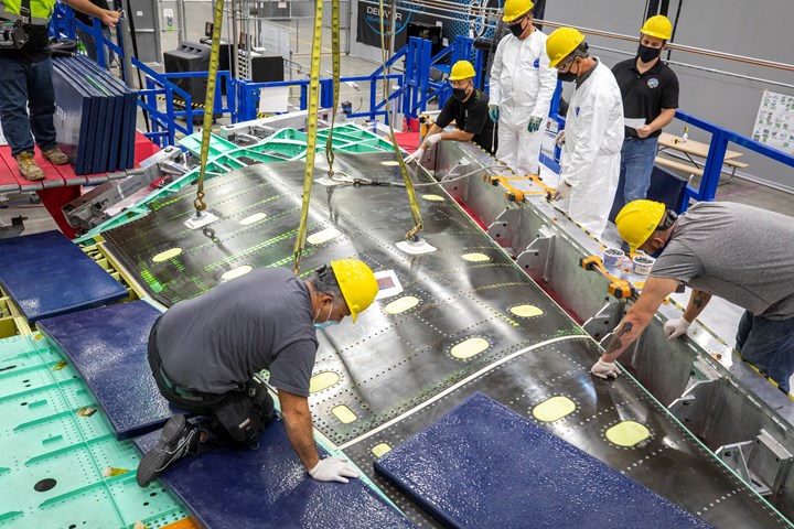
Building and assembling the wing. Mechanical fasteners were used along with bonding to secure the composite top and bottom wing skins to the metallic ribs and stiffeners in the wing interior. Photo Credit: Lockheed Martin
Long, thin nose: Sandwich construction, autoclave cure
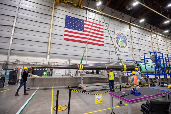
Almost a third of the aircraft is taken up by the 34-foot-long nose. According to NASA, the length and shape of this nose is an essential feature to reconfiguring shock waves during supersonic flight.
The 299-pound nose is fabricated in two halves, right and left, that were adhesively bonded and bolted together along the upper and lower seams. Typically, a nose like this would be built as an upper and lower half, Folsom says, but the length and narrowness of the X-59’s nose required extra stiffness on the top and bottom to prevent bending. “The overlapping of the laminates at the joined edges was strategically placed onto the top and bottom of the nose, meaning there were double the layers of fibers and added stiffness,” he says, noting that the region acts similarly to the caps of an I-beam.
Each half was built as a sandwich panel with seven plies of MTM-45 fabric on the outer skin laminate, three plies on the inner skin and honeycomb core in between. These were laid up on female molds under vacuum bags and then cured in an autoclave. Lockheed Martin initially designed the nose, and then contracted its final laminate design and manufacture to another supplier.
Additional composite components
Like the nose, the rest of the composite components on the X-59 were designed and assembled by Lockheed, but manufactured by fabricating partners.
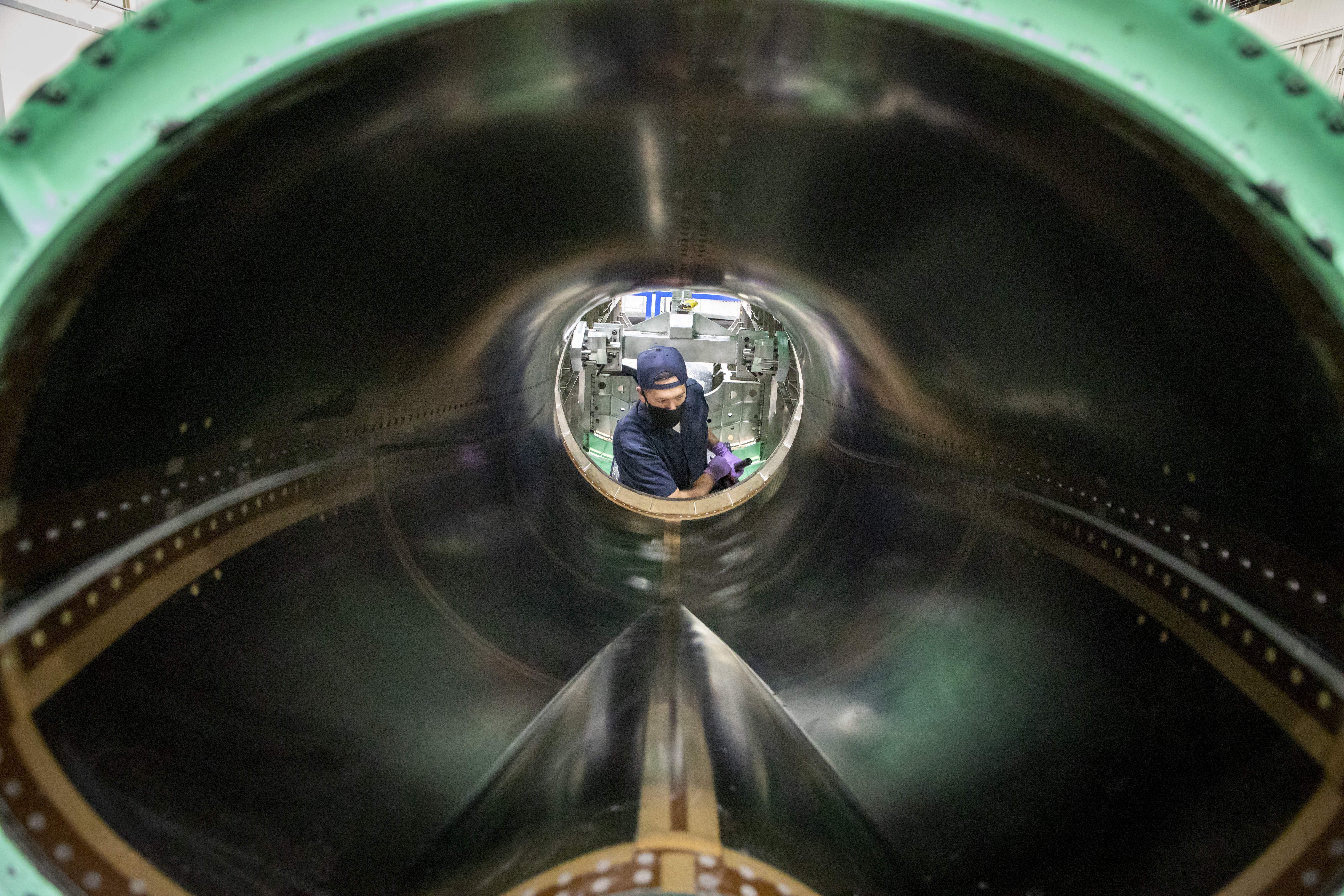
Inspecting the inlet duct. The composite inlet duct, designed by Lockheed Martin and manufactured by a partner, is designed for placement above the wings of the aircraft along with the engines and several other systems. Photo Credit: Lockheed Martin
The nose and the wing skins are the largest composite components, but Richardson says the most challenging to design were some of the smallest: the flaperons, ailerons and the rudder. “These are parts that get very thin at the trailing edge, and require a lot of handwork and artistry to get them to come together and to meet the loads that are placed on them,” he says. “They’re very highly loaded parts on the aircraft.” The ailerons and flaps are only 3 inches thick.
Semi-automated assembly
Once all of the metallic and composite components were manufactured, Lockheed Martin Skunk Works began assembly of the X-59 in 2018 and completed it in late 2021.
New for the X-59 project, Lockheed Martin Skunk Works recently acquired an Electroimpact (Mukilteo, Wash., U.S.) robotic drilling machine called the Combined Operation: Bolting and Robotic AutoDrill system, or COBRA.
This was acquired specifically for use in wing assembly. According to Folsom, one of the most labor-intensive processes involved in building a composite wing skin — or any large composite laminate via AFP, for that matter — is the assembly. The X-59 wing interior comprises metallic spars and ribs, all of which needed to be mechanically fastened to the wing skins.
“A bunch of guys on their hands and knees, crawling around drilling it by hand is kind of oxymoronic” after so much automation is used to build the skins themselves, he says. He explains that metallic substructures were chosen “since they have linear reactions to forces for ease of analysis. Their initial failure mechanism is to bend rather than snap, and they can easily accommodate the multitude of attach points for subsystems like fuel pumps and probes.”
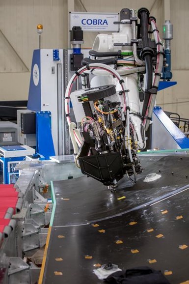
Automated drilling. For this program, Lockheed Martin acquired an Electroimpact seven-axis robotic drilling system to save time and labor on assembly of the X-59 wing. The company plans to continue using the machine for other programs. Photo Credit: NASA
The COBRA is a seven-axis robotic drilling tool capable of drilling through the wing skin, adhesive and aluminum frame in one shot, and inspect and countersink it, per the programmed pattern. “We drilled thousands and thousands of holes that way automatically over the course of about five days, which saved us months of doing it by hand as well as eliminated human error,” Folsom says.
The entire wing section was assembled upside-down, Folsom explains. The lower composite skin was attached to the metallic (mostly aluminum, with some titanium in areas that need higher strength) interior parts via adhesive bonding and mechanical screws. Then the entire structure was flipped over and the upper wing skin was attached using screws and a temporary adhesive bond. This would allow later unscrewing and lifting off of the top wing skin to install the final subsystems and fuel tanks. After installation of all subsystems inside the wing, the wing skin is then re-fastened and bonded with AMS 3277 sealant.
Testing and steps toward first flight
In early 2022, the completed airframe was transported by land to Lockheed Martin’s test facility in Fort Worth, Texas, U.S. There, it underwent several months of ground testing to ensure the vehicle itself can withstand the loads and stresses that typically occur during supersonic flight, and to calibrate and test the fuel systems.
In late March, the X-59 was moved back to Palmdale to finish installation of the engine, wiring and several subsystems, to be followed by months of systems and engine tests leading up to the first flight by the end of 2022.
Richardson explains, “As we go into flight tests, NASA will take on even more roles in the program as far as test engineers and providing flight test support. And then as we migrate through the flight test program, they will start to do maintenance on the aircraft until finally we turn over the keys to NASA and they own it and maintain it themselves.”
At that point, NASA will begin its own flight tests, with plans to conduct its community response study between 2024-2026, flying the plane over selected U.S. communities. See a full timeline of the X-59’s milestones at www.nasa.gov/specials/X59/whats-next-for-x59.html.
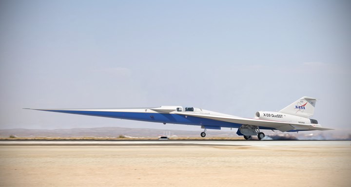
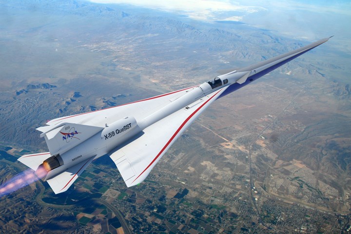
Preparing for first flight. After all final systems are installed and tested on the ground, the X-59 (artist rendering shown here) is expected to begin flight tests by the end of 2022. Photo Credit: Lockheed Martin
While much will be learned when the X-59 QueSST finally takes to the skies, there have already been many lessons learned by the design and manufacturing teams on the ground. For example, Buonanno predicts several novel design elements of the aircraft could carry over to commercial supersonic plane developments in the future — specifically, the long, narrow nose and, assuming tests are successful, the placement of the engine and other structures above the wings to deflect sound. “I think any type of low-boom, supersonic aircraft will need a long, composite nose like the one on the X-59 [to achieve the correct balance,]” Buonanno says.
About the materials used, he says, “Future commercial aircraft would probably use higher performing composite materials than we used on X-59. While the X-59 only needs to carry one pilot and fly supersonically for a relatively brief time, commercial aircraft need to carry many people over long distances, making weight far more critical.”
Lockheed also plans to transfer the manufacturing and assembly methods used on the X-59 to other projects, particularly the COBRA drilling system purchased for this program. Folsom notes that assembly by hand is often the go-to method for one-off and prototype vehicles, but “on this airplane, we did a kind of hybrid [of both hand assembly and automated processes], and we did that on purpose to see how much time and money were spent drilling by hand versus the equipment and programming and everything it takes to do it automatically.”
He adds, “There are no other airplanes like this, and we will not make a second one. It is specifically designed to generate noise to help us to repeal those overland supersonic regulations. The X-59 is a very unique airplane in the history of aviation.”


Related Content

Carbon fiber composite pallet revolutionizes freight industry
LOG Point Pallet fuses advanced materials with innovative design and manufacturing to improve supply chains worldwide.
Read More
All-recycled, needle-punched nonwoven CFRP slashes carbon footprint of Formula 2 seat
Dallara and Tenowo collaborate to produce a race-ready Formula 2 seat using recycled carbon fiber, reducing CO2 emissions by 97.5% compared to virgin materials.
Read More
Pultruded CFRP chassis enables 36% payload increase for specialized commercial vehicles
CarbonTT’s quadraxial NCF composite chassis adds 185-kilogram capacity to Borco Höhns’ 3.5-ton Fiat Ducato market vehicle.
Read More
Composite bipolar plates provide 81% improvement to hydrogen fuel cell power density
Ultra-thin CFRTP plates developed by Hycco achieve a 7.5 kilowatt/kilogram power density, high durability for fuel cells in long-flight drone and heavy-mobility applications.
Read MoreRead Next

Is supersonic flight making a comeback?
Boom Technology (Denver, CO, US), a 2014 start-up aircraft developer, is in the process of building the XB-1, a flying 1/3-scale demonstrator of its supersonic (faster than sound) commercial aircraft.
Read More
Kaneka BMI material attains >25% lead time, >20% tool cost reductions in Janicki evaluations
Process evaluations find that novel BMI polymer chemistry addresses longstanding manufacturing challenges of BMI tooling prepregs while maintaining high temperature performance and durability.
Read More
Sentherm conductive polymers match aluminum thermal performance, cut weight
Tailored filler networks, anisotropic material design and manufacturing process control achieve hybrid polymers for EVs, batteries and other automotive-related electronics with 95% of aluminum’s thermal performance and 25-45% reduced component weight.
Read More