
Designing and manufacturing turbine test nacelles
Michigan-based Ground Test Solutions (GTS) shares the design and manufacturing processes involved in building composite nacelle components used in testing jet and helicopter engines.
.jpg;width=70;height=70;mode=crop;format=webp)


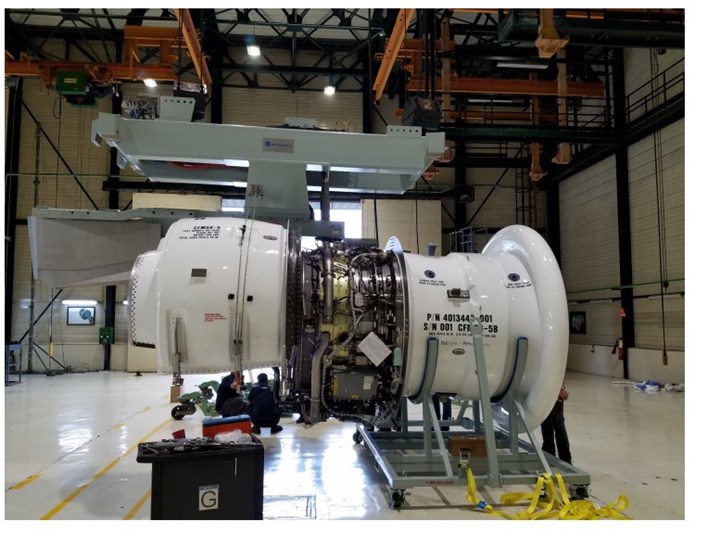
Michigan-based Ground Test Solutions (GTS) manufactures composite components for test versions of aircraft nacelles, which are used by engine manufacturers for pre-flight testing and by airlines for aftermarket testing. Source, all images | Ground Test Solutions
Aircraft nacelles — the multi-component covers that house jet engines on an aircraft — are often manufactured from composite materials. These are complex components that need to meet stringent requirements such as temperature, fire resistance and noise damping.
Before an engine is ever installed onto a flight nacelle and put into an aircraft, however, it needs to go through a series of tests on the ground, making sure it can withstand the needed temperatures and altitudes, bird strikes and other conditions. Therefore, test nacelles, similar to their flight counterparts but with slightly different requirements, are built specifically to house engines within a specially designed, ground-based testing unit.


One of the few companies that specializes in test nacelles is Ground Test Solutions (GTS, Grand Ledge, Mich., U.S.). GTS was founded 15 years ago by Tom Hamel, president, and Mark Jeffreys, field service manager. Hamel and Jeffreys both previously worked at Pratt & Whitney, which also manufactures test nacelles in addition to aircraft engines.
GTS’ 26,000-square-foot facility employs about 40 people and manufactures bellmouth inlets, thrust reverses, nozzles and plugs, boattails and complex ducts, all of which are composites-intensive and built specifically for jet and helicopter test nacelles for pre-flight testing and aftermarket use.
According to Hamel, only three companies in the world build aircraft test nacelles: GTS, Pratt & Whitney and Safran. “And GTS is, of course, the smallest by far. However, what we offer is the best value and lowest cost to the customer,” he says.
What’s the difference between a test nacelle and a flight nacelle? “Since it’s used for ground tests only, there are certain features that are not needed for the test nacelle, like an outer, aerodynamic skin,” explains Nick Dobson, engineer at GTS. “That said, we do build the test nacelle in such a way to match characteristics like weight and stiffness for the actual flight nacelle, so that it matches up for testing purposes.”
What type of tests do the nacelles go through? “Typically the customer will put these in a closed test cell that is acoustically treated to eliminate noise issues, and it’ll go through a number of different test cycles” as designated by the Federal Aviation Administration (FAA), Dobson says. These can include testing the nacelle’s overall endurance and wear over time, tolerance against bird strikes, water seals, altitude performance, resistance to icing and more. He adds that the FAA specifies testing requirements both for engines prior to service, and retesting of in-service engines after a number of flight hours to make sure they are still good to go.
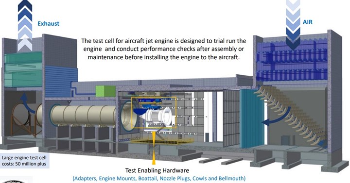
An example of an aircraft test cell, with the test nacelle pictured in white in the middle.
Designing a test nacelle
From design to manufacture, each test nacelle takes about a year to develop and produce. “We design it, we tool it and we build it. It’s all very vertically integrated,” Hamel says.
The design process starts with the design specifications provided by the engine manufacturer. “We get the shape of the flow path, the temperatures and pressures, for the particular engine you’re working with,” Dobson says. From this, GTS uses Dassault Systèmes’ (Waltham, Mass., U.S.) SolidWorks to generate and analyze CAD models for the nacelle, adapting the materials, ply schedule, adhesive and other factors depending on simulating the behavior from temperature and pressure loading simulations. “We really push the materials to their limit in terms of temperature and strength,” Dobson adds.
Then, GTS presents its design proposal to the customer, and makes adjustments as needed until the final design is established.
Complex tooling and manufacture
Next, tooling is designed and built in-house, from glass or carbon fiber, or machined from metal depending on the needs for a particular component.
Most of the structures for a test nacelle are built with carbon fiber prepreg and honeycomb core, hand-laid on open molds and then cured under vacuum in an oven.
“The materials we use varies, depending on the temperature requirements needed,” Dobson notes. For a typical project, GTS occasionally manufactures structures from fiberglass, though carbon fiber prepreg from Toray Composite Materials America (Toray CMA, Tacoma, Wash., U.S.) is more common, cut via a Gerber (Tolland, Conn., U.S.) CNC cutting table, and sandwiching aluminum honeycomb. These structures are hand laid on open molds built in-house and then cured under vacuum bags in GTS’ 24 × 20-foot oven. After cure, the parts are finished in a paint booth.
GTS also provides maintenance services to its equipment. “We go into the field around the world and repair the composites if they get damaged or are showing wear,” Dobson says.
Much of the time and skill needed to build these components comes from the complexity that comes from having to redesign nacelle components for a non-flight engine. “Everything — the composite components, the latches, the hinges, the metal interfaces — it all has to be designed so that its weight and center of gravity simulate the flight nacelle, even though the components are a bit different in design for a ground test,” Hamel says. “And of course it all has to be designed to take even more loading than in a typical flight situation because it’s designed to be tested to its limit.”
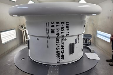
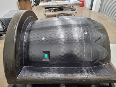
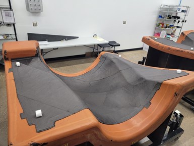
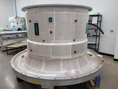
For a test nacelle, the inlet duct typically features a trumpet-shaped curve, making it a challenge to lay up. Pictured are a nacelle laid up and ready for cure in the cleanroom (bottom image) and a finished LEAP 1B test nacelle after painting (top image).
For example, one of the primary components for a test nacelle is a bellmouth inlet duct (pictured left), which, unlike the inlet duct on a typical flight nacelle, is designed with a trumpet-like flare in order to more efficiently bring air into the nacelle without the pressure and force created from actual flight. “It’s a really complex curvature to try to lay up in prepreg and honeycomb. For this we use Hexcel’s (Stamford, Conn., U.S.) Flexcore honeycomb, because it’s designed to be able to wrap around curves,” Dobson says. For a typical bellmouth, he says about 8 to 20 plies of Toray CMA carbon fiber prepreg may be used on each side, sandwiching the aluminum honeycomb.
“The result is a very light, stiff structure that is used to bring the air into the engine for measuring important parameters of the engine’s performance,” Dobson says.
Another complex component is the thrust reverser — called a substitute thrust reverser, in this case, since there’s no actual thrust for ground tests — which encases the sides of the engine. “These are the most complex structures we build,” Dobson notes, because they have to be built in two halves that can be opened like a clamshell to install and remove the engine for testing. These two halves are connected by a specially designed, metallic hinge system on the top and bottom.
Designing the parts to withstand the needed temperatures is also a challenge, particularly for parts like the substitute thrust reversers and cowls which encase the engine directly. “We use the highest temperature carbon fiber prepreg we can find, and add heat shields and heat blankets to it where it gets really hot,” Dobson says. The cowl components are also designed with specific grooves and bifurcations where equipment needs to be mounted for taking measurements during testing.
“One thing we really do is push the capability of our composite materials in terms of where and how we use them, so we end up working with Toray, our main prepreg supplier, a lot. They’ve been able to do some testing on materials for us to prove out adequate strength and temperature capability for these applications,” Dobson adds.
Looking forward: LEAP
GTS is one of two providers for the test system for CFM International’s (Cincinnati, Ohio, U.S.) LEAP 1A and 1B, which are used on single-aisle aircraft like the Boeing 737 MAX and the Airbus A320neo family.
For these, GTS is building aftermarket test nacelles, sold to customers such as the FAA and airlines to test the flight engines after use.
“These structures are complex, and made from both composite and metal,” Dobson explains. The primary bellmouth, cowl, boattail and substitute thrust reversers for each nacelle are built from a combination of Toray 2510 carbon fiber 12K plain weave prepreg plies and Flexcore honeycomb core, manufactured with carbon fiber composite tooling to match the coefficient of thermal expansion.
Dobson adds, “The LEAP is an exciting program for us. We’ll be building 30-40 nacelles over the next 10 years.”


Related Content

TU Munich develops cuboidal conformable tanks using carbon fiber composites for increased hydrogen storage
Flat tank enabling standard platform for BEV and FCEV uses thermoplastic and thermoset composites, overwrapped skeleton design in pursuit of 25% more H2 storage.
Read More
One-piece, one-shot, 17-meter wing spar for high-rate aircraft manufacture
GKN Aerospace has spent the last five years developing materials strategies and resin transfer molding (RTM) for an aircraft trailing edge wing spar for the Airbus Wing of Tomorrow program.
Read More
Materials & Processes: Composites fibers and resins
Compared to legacy materials like steel, aluminum, iron and titanium, composites are still coming of age, and only just now are being better understood by design and manufacturing engineers. However, composites’ physical properties — combined with unbeatable light weight — make them undeniably attractive.
Read More
Cryo-compressed hydrogen, the best solution for storage and refueling stations?
Cryomotive’s CRYOGAS solution claims the highest storage density, lowest refueling cost and widest operating range without H2 losses while using one-fifth the carbon fiber required in compressed gas tanks.
Read MoreRead Next

Nacelle manufacturers optimize hand layup and consider closed molding methods
Focused on optimizing traditional hand layup, nacelle and thrust reverser manufacturers cast an eye on future use of automation and closed molding.
Read More
The potential for thermoplastic composite nacelles
Collins Aerospace draws on global team, decades of experience to demonstrate large, curved AFP and welded structures for the next generation of aircraft.
Read More
CW’s 2024 Top Shops survey offers new approach to benchmarking
Respondents that complete the survey by April 30, 2024, have the chance to be recognized as an honoree.
Read More