
Composites steady radio telescope reflector
Precise carbon fiber-reinforced dish prototype could be the model for as many as 2,500 telescopes in the Square Kilometre Array.

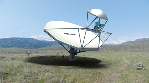
The Square Kilometre Array is a multinational effort to deploy thousands of high-performance radio telescopes in remote regions of South Africa and Australia to receive space-based radio signals. One design possibility is a 15m/49.2-ft diameter Gregorian offset type (illustrated here), which features a primary and secondary dish-type reflectors and secondary support structures made with carbon fiber composites. A prototype is being manufactured by the National Research Council Canada (Ottawa, Ontario, Canada). Source: NRC-Canada
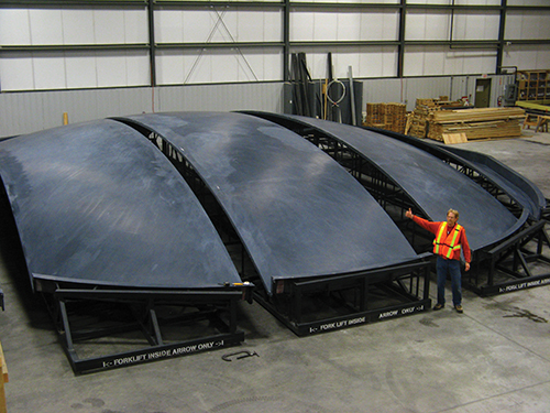
Step 1: The mold for the 15m/49.2-ft diameter DVA-1 dish was supplied to NRC-Canada by Janicki Industries. It was delivered in five sections and assembled at NRC-Canada’s facility in British Columbia. The accuracy demanded of the dish required a tool that could hold tight tolerances over a very large surface area. Source: NRC-Canada
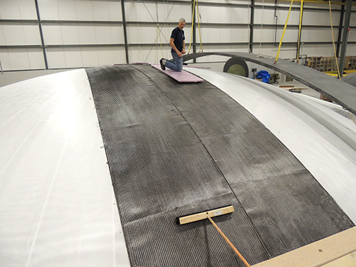
Step 2: A&P Technology’s QISO triax braided carbon fiber is layed up over the ply of glass fiber that covers the aluminum reflective layer of the DVA-1 primary dish. The arched, suspended carbon fiber panel on the right is scaffolding used by workers to access the mold without touching the mold or plies. Source: NRC-Canada
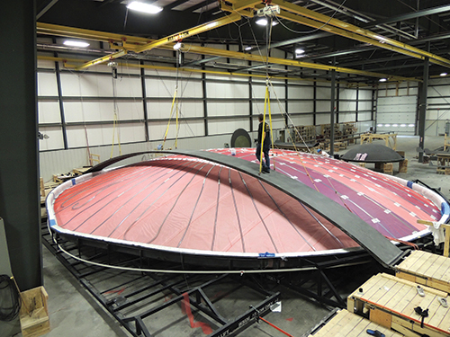
Step 3: The primary dish, during preparations for infusion. NRC-Canada says surface error of the mold is less than 0.5 mm/0.02 inch, producing a final part with a surface error of just. 0.9 mm/0.04 inch. Source: NRC-Canada
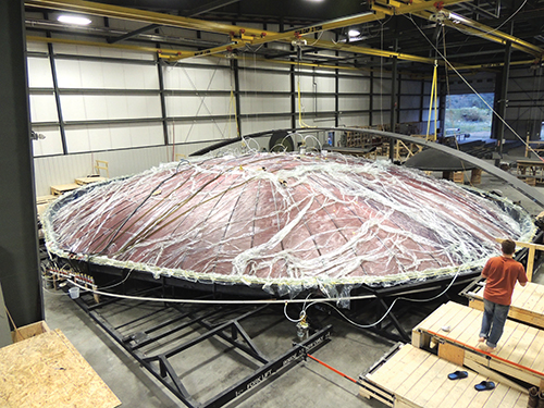
Step 4: DVA-1 primary dish, bagged and beginning infusion. The dish comprises a thin layer of aluminum, backed by glass and carbon fiber. The resin is a vinyl ester, chosen because of its ability to maintain dimensional tolerance. Infusion takes about an hour. Source: NRC-Canada
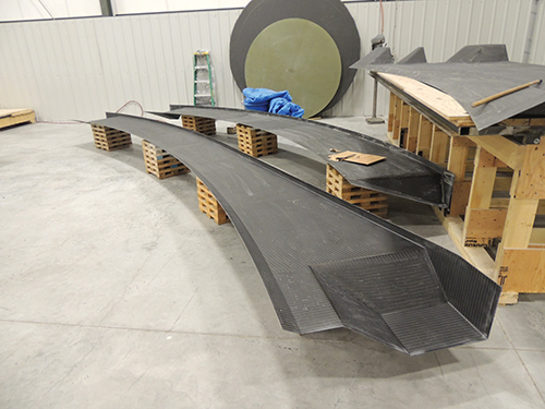
Step 5: Primary dish rim sections, prior to bonding to the primary dish. Note the pockets in some of the rims, which will house the dish rim connectors. Source: NRC-Canada
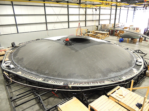
Step 6: Finished DVA-1 primary dish, with dish rim, as painting begins. The secondary dish can be seen in the background. Source: NRC-Canada
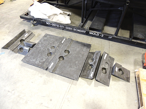
Step 7: These DRC inners show the half-hemispheres of the ball-and-socket joint used to encapsulate the metallic bolts that connect the dish to its primary support structure. Source: NRC-Canada
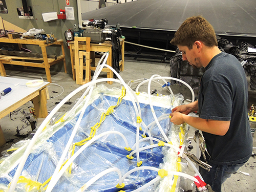
Step 8: An NRC-Canada employee bags a DRC in preparation for infusion. Source: NRC-Canada
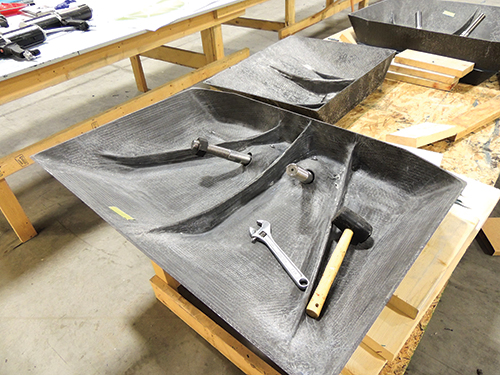
Step 9: A fully molded DRC, with two threaded bolts emerging from the composite ball-and-socket joint. The DRC will be bonded into the DVA-1 rim; the metallic bolts will be used to attach the dish to its primary support structure. Source: NRC-Canada
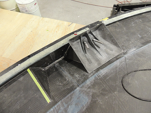
Step 10: A finished DRC sits next to the pocket in the dish trim into which it will be adhesively bonded. Source: NRC-Canada
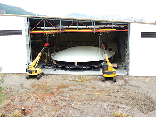
The finished, painted DVA-1 primary dish is moved out of the fabrication facility in preparation for transport to the assembly site. Source: NRC-Canada
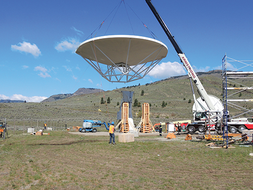
The DVA-1, attached to its primary support structure and now weighing 8.7 metric tonnes (9,200 lb), is lifted into place for attachment to the pedestal on which it will operate during the testing and evaluation phase. Source: NRC-Canada
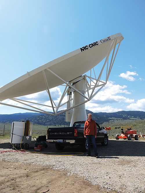
NRC-Canada’s DVA-1 primary reflector, installed on its pedestal near Penticton, British Columbia, Canada. The secondary dish and hardware platform will be installed during the summer of 2014. Source: NRC-Canada


There are two types of telescopes commonly used to explore the universe. Optical telescopes, such as Hubble and James Webb, rely on visible light emitted from the stars, planets and other bodies in space and produce photographic images. The other type, radio telescopes, are designed to detect the radio waves emitted by these same bodies and other sources.
A key advantage of radio waves is that they can pass through gases, clouds and other obstacles in space that might block or obscure visible light, making visible many bodies that otherwise could remain hidden. Radio signals also offer information about invisible aspects of the universe: gravity, magnetism, black holes and dark energy. These data help astronomers and physicists develop a better understanding of how the universe began, how it’s organized, how it behaves and how it’s evolving.


Because radio signals have longer wavelengths than visible light, the radio telescope used to detect them doesn’t have to be as precisely shaped as its optical cousin. But to obtain the same level of detail and resolution as the optical version, radio telescopes must have a much larger collection area. The largest radio telescope in the world, with a main reflector dish diameter of 300m/984 ft, is the Arecibo telescope, in Puerto Rico. However, even a dish of this size cannot match the resolution of an optical
telescope.
To produce photo-equivalent detail and resolution, a radio telescope’s reflector dish must have an area measured in kilometers, not meters. This can be accomplished in one of two ways. One is to manufacture one large dish that measures about 1 km2/0.39 mi2. Such a large dish, however, would have to be in a fixed position and thus could not be repositioned to receive signals from different regions of space. Ideally, then, radio signal exploration would require a large adjustable dish, able to maintain positional accuracy within ±1 mm/0.04 inch. A more feasible alternative is to manufacture a series of smaller dishes in an array known as an interferometer. Practically, these individual dishes may be located anywhere, as long as each can “see” the same portion of the sky. The goal of an interferometer, then, is a combined dish area of about 1 km2. Signals received by each dish in an interferometer are centrally collected and processed by a correlator, which combines the signals (adjusting for each telescope’s position in the array) to simulate a much larger telescope.
This is the premise of the Square Kilometre Array program (SKA, Manchester, U.K., www.skatelescope.org). A multinational effort, its participants hope, by 2030, to have in place thousands of radio telescopes clustered in remote regions of South Africa and Australia. SKA envisions the manufacture of three types of radio telescope: A conventional circular dish, a low-frequency aperture array and a mid-frequency aperture array. SKA has gathered consortia of manufacturers and software developers to create the telescope systems and the other equipment that the project requires.
One of the first deliverables is a dish type, with a 15m/49.2-ft diameter primary reflector, which is being competitively prototyped by three organizations, one in Canada (called DVA-1), one in China (DVA-C) and one in South Africa (MeerKAT 1). Of these, only the Chinese and Canadian versions employ carbon fiber composites in significant amounts. The Canadian fabrication marks one of the most ambitious applications of carbon fiber composites in a dish structure of any kind.
Building the perfect dish
The Canadian DVA-1 dish is an offset Gregorian type. Its mostly composite 15m primary reflector reflects captured radio signals up to a 4m/13.1-ft diameter secondary reflector dish, positioned on support legs over the main dish. From the secondary reflector, radio signals are received by hardware on a feed support platform located between the secondary and primary reflectors (see opening image). Of the other critical structures, some are fabricated from metals and some are fabricated from composites. The main dish’s support truss, as well as the pedestal on which it rests, for example, are metallic. However, the feedlegs that support the secondary reflector and feed support platform are manufactured with carbon fiber composites.
DVA-1 was built by the National Research Council Canada (NRC-Canada, Ottawa, Ontario, Canada). Most production work was done at NRC’s facility in Penticton, British Columbia. Gordon Lacy, an NRC-Canada mechanical engineer and DVA-1’s lead engineer, has been working on dish design and development since 2006, adjusting to shifting political and financial winds as a variety of governments and government agencies around the world entered and exited the SKA project. He admits that the decision to use carbon fiber might be questioned because of the material’s cost, but when NRC-Canada looked at the mechanical requirements, he says carbon fiber was the logical choice.
“The dish requires very high precision of the reflective surfaces under wind, gravity and temperature changes,” he notes. “For the best radio-frequency performance, we need the reflectors to retain their design shape under all conditions. We also need the reflector to have a high reflectivity to radio waves. For this we have developed an embedded metallic layer. Carbon fiber has a very high stiffness-to-weight ratio, which enables us to more easily meet the gravitational distortion requirements. Carbon fiber composites also have very low coefficients of thermal expansion [CTE], which helps us to meet our thermal stability requirements.”
To meet all of DVA-1’s tolerance requirements, NRC partnered with composites manufacturers that were accustomed to working to that level of precision. Among the first was Janicki Industries (Sedro-Woolley, Wash.), which supplied the massive mold for the main reflector. The tool is possibly the most critical component, says Lacy, because its accuracy dictates the dimensional tolerance of the finished product. “The tool had to keep the shape of the mold, or we had to be able to predict very accurately what the shape change was going to be,” he recalls. “We opted just for keeping the shape under control, so it’s very close to the mold shape.”
Janicki manufactured a five-piece, prototype-type mold of fiberglass, topped by a putty layer, on a steel substructure. Lacy says NRC-Canada used a FARO (Lake Mary, Fla.) laser tracker to accurately fix mold position as the sections were assembled. “It’s a somewhat flexible mold,” he explains, “so we were then able to push up and pull down on the surface from underneath a little bit to adjust it.”
The fully assembled mold offers a surface error of less than 0.5 mm/0.02 inch, reports Lacy. As a testament to the accuracy of the finished, molded main reflector, he adds, a laser scan of it was compared to the CAD model, revealing a surface error — 0.9 mm/0.04 inch — that barely exceeded that of the mold. “You can’t get less than the mold’s error, of course,” Lacy quips. “It means that there is almost no shrinkage in the part.”
The main reflector measures 5.3 mm/0.21 inch thick and comprises — from signal-facing side to back side — a 0.08-mm/0.003-inch layer of aluminum for signal reflectivity, a ply of woven glass fiber to protect against galvanic corrosion, and several plies of A&P Technology’s (Cincinnati, Ohio) QISO triaxial braided carbon fiber — in this case, Toray’s (Tokyo, Japan) T700 material. The entire layup is bagged and the resin, HETRON 922 vinyl ester from Ashland Performance Materials (Columbus, Ohio), is infused in one shot, in about an hour. Lacy reports that infusion provides the greatest process control most affordably. “It’s such a large part that infusion gave us the best trade-off in terms of performance and cost.” Infusion modeling was done by Lacy with Polyworx (Nijverdal, The Netherlands) software.
Clever connectors
The main reflector, when installed, must be anchored to the primary support structure, a latticework of metallic tubes that joins the reflector to the mechanized pedestal on which it rests. Each dish must connect to 14 tubes at eight connection points (some connection points receive two tubes). Each connection must be adjustable as the dish is erected, and then tightened and secured when it is properly positioned. Connection points are built into what’s called the dish rim, also a composite. The rim is molded separately and bonded to a vertical flange at the edge of the dish.
Lacy in cooperation with NRC-Canada partner Profile Composites’ (Kingston, Wash.) CEO Geoff Wood, worked on a dish rim connector (DRC). It features a unique ball-and-joint design that cleverly and securely anchors the dish to the support structure. There are several types and sizes of DRC, depending on the DRC’s location and whether or not it’s accommodating one or two support structure tubes.
A 10.2-inch/259-mm long threaded stainless steel bolt, with a 4-inch/102-mm ball on one end, is enclosed in the DRC, which has two primary parts, the DRC inner and the DRC outer. The DRC inner is a compression-molded carbon fiber base that contains half of the ball socket(s) for one or two bolts. The DRC outer is similar and contains each socket’s other half. The bolt’s ball, coated with mold release to keep it “free” in the socket, is placed in the DRC inner and then covered with the DRC outer, thus completing the ball-and-socket joint. These two halves are then bonded together with a methacrylate adhesive (see Step 9). The assembled DRC is then bonded into its own pocket in the dish rim, also with methacrylate adhesive.
When complete, the dish is equipped with eight DRCs, each with either one or two threaded bolts protruding and ready to be attached to support tubes during dish erection. Lacy says that after a dish is installed and oriented on the support structure per specification, CHOCKFAST ORANGE, a poured-in-place epoxy chocking compound from ITW Polymers Coatings (Montgomeryville, Pa.), will be injected into each ball joint to provide rigidity and increase strength. “The fit [of the ball joint] is really quite good,” Lacy explains. “But since we want the best possible positional accuracy, any movement in any joint is detrimental to this alignment.”
A little wind
NRC-Canada completed the primary dish for DVA-1 in fall 2013. The next step was to transport the assembled dish, weighing 2.8 metric tonnes (about 6,170 lb), via helicopter to its pedestal, which had been constructed in a secluded “radio-quiet” area about 5 km/3 miles from Penticton. However, as it approached its destination, tethered beneath the helicopter in a horizontal position, a sudden and relatively violent gust of wind flipped it into vertical position. When the gust abated, the dish fell back into its original horizontal position. Although it was still tethered to the helicopter, the dish had buckled, leaving it badly misshapen and deformed (see end note).
Initial reaction to the dish damage at NRC-Canada was pessimistic. “Most people thought it was a write-off,” says Lacy. But as the organization studied its options, repair seemed more and more viable. The first step was to “pop” the dish back into shape with the help of a local industrial-services company that deploys inflatable bags to help move cars and trucks involved in accidents. The bags were inserted under the dish and inflated to “push” the deformed sections back into their original shape.
It worked, says Lacy, and the dish remained remarkably close to the tolerances measured before it was damaged. There remained, however, 21 cracks in the composite structure. These were scarfed, patched, bagged and re-infused at the assembly site under an improvised polymer dome erected over the dish to keep out the cold weather. In the end, he says, NRC-Canada was able to completely restore the dish to specification. “It was a blessing in disguise,” Lacy says of the wind damage. “The process really demonstrated that it could be repaired.”
Installation, operation
The refurbished dish was ready again to join the support structure, and the two together weigh 8.7 metric tonnes (nearly 19,200 lb). They were lifted onto and attached successfully to the pedestal. At press time, the telescope was awaiting installation of the secondary collector (a smaller version of the primary collector, also made at NRC-Canada), as well as the feed support platform that holds the signal-receiving equipment. The secondary collector and the platform are supported by a latticework of carbon fiber tubes designed and manufactured by Profile Composites. Profile’s Wood says these tubes also are made from A&P Technology’s unidirectional woven fiber in a tubular preform shape, with elastomeric fibers woven in to give the preforms flexibility for easy fit over mandrels. Infused with epoxy, the tubes are made in three diameters, 75 mm to 100 mm to 151 mm (2.9 to 3.9 to 5.9 inches), in a variety of lengths, with wall thicknesses that range from 4 mm to 6 mm (0.26 inch to 0.24 inch).
After the entire dish is assembled and functional, NRC-Canada will start receiving radio signals as part of the overall testing and evaluation program for SKA. Under the current SKA schedule, a preliminary design review will be conducted in fall 2014, followed by critical design review in spring 2015. If NRC-Canada’s design is selected, a second prototype will be produced in 2016. Phase 1 will follow, which calls for the manufacture of 150 receivers for installation in South Africa and another 50 to 60 receivers for installation in Western Australia. Phase 2 of SKA calls for a substantial ramp-up in production, culminating in the manufacture and installation of a total of 2,500 radio telescopes across the two countries.
Lacy admits that Phase 2 “will require a great deal of international investment,” which is still being arranged and coordinated. However, the fact that SKA has survived and persisted long enough to produce the radio telescope prototypes that are currently under evaluation shows that the project has developed some momentum. The world might yet see the installation of a very large array of very large carbon fiber radio telescopes.
Editor's Note: View the video of dish transport, damage and repair efforts here.


.jpg;maxWidth=300;quality=90;format=webp)


Related Content

Materials & Processes: Fabrication methods
There are numerous methods for fabricating composite components. Selection of a method for a particular part, therefore, will depend on the materials, the part design and end-use or application. Here's a guide to selection.
Read More
The making of carbon fiber
A look at the process by which precursor becomes carbon fiber through a careful (and mostly proprietary) manipulation of temperature and tension.
Read More
Braskem demonstrates PP solutions using Weav3D composite lattice technology
Partnership combines Braskem’s polypropylene sheets with Weav3D Rebar for Plastics technology to address new structural, automotive applications requiring high-strength, lightweight material solutions.
Read More
PEEK vs. PEKK vs. PAEK and continuous compression molding
Suppliers of thermoplastics and carbon fiber chime in regarding PEEK vs. PEKK, and now PAEK, as well as in-situ consolidation — the supply chain for thermoplastic tape composites continues to evolve.
Read MoreRead Next

CW’s 2024 Top Shops survey offers new approach to benchmarking
Respondents that complete the survey by April 30, 2024, have the chance to be recognized as an honoree.
Read More
From the CW Archives: The tale of the thermoplastic cryotank
In 2006, guest columnist Bob Hartunian related the story of his efforts two decades prior, while at McDonnell Douglas, to develop a thermoplastic composite crytank for hydrogen storage. He learned a lot of lessons.
Read More
Composites end markets: Energy (2024)
Composites are used widely in oil/gas, wind and other renewable energy applications. Despite market challenges, growth potential and innovation for composites continue.
Read More