
Composites Protect Pipe in Downhole Environment
Glass-reinforced epoxy provides a durable and affordable liner for alternative pipe used in enhanced oil recovery.


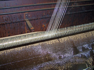
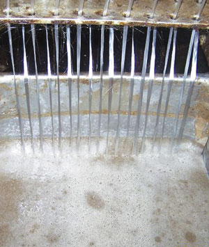
Step 2: Rovings are wetout in a resin bath with a toughened epoxy just before they are transferred to the winding head.
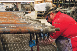
Step 6: Cured and ground liners are then inserted into the host pipe and prepared for grout injection.
The stereotypical Hollywood image of a freshly tapped oil field usually conjures up scenes of a wide-open scrubland dotted with cactus, a blazing overhead sun and a tall wooden derrick. Out of the top of the derrick sprays thick, black crude oil, covering everything around it, while oil-slicked riggers dance and rejoice at having finally struck “black gold.” As this somewhat fanciful image implies, oil and natural gas reserves trapped thousands of feet below ground are subject to hydrostatic pressure. This naturally occurring phenomenon drives the oil or gas to the surface, making it relatively easy to extract. This pressure, however, diminishes over time, even when substantial amounts of recoverable oil or gas still remain in the ground.
To tap what remains, oil field operators must then introduce pressure into the subterranean reservoir — a tactic known as enhanced oil recovery (EOR) or secondary stimulation. One of the most used and effective methods is to pump water into the reservoir through a series of strategically placed injection wells. Used in both land- and sea-based oil and gas extraction, injection wells can range in depth from around 2,000 ft/610m to 17,000 ft/5,182m or more. Several injection wells might be situated in a field to serve one or more production wells. An injector may run continuously in service of an extraction well, or it may run only intermittently.


Although EOR sounds relatively simple, it introduces several complications: First, the water itself can negatively affect pipe longevity, and depending on the source, level of acidity and/or chemical additive content, may accelerate or exacerbate pipe corrosion. Second, injected water temperature typically ranges from 100°F to 400°F (38°C to 204°C). Third, service pressure can range from 500 psi (34.47 bar) to 10,000 psi (689.5 bar) or more, depending on the application. Given this hostile downhole environment, injector pipe requires substantial engineering, particularly with regard to materials, to accommodate and manage the thermal stress and pressure and optimize service life.
In such difficult and corrosive downhole environments, oil and gas producers have typically relied on pipe made from metal alloys of chrome, stainless steel, or nickel to resist chemical and water attack. The challenge of such materials — particularly of late — has been their high cost as steel prices have steadily increased.
One alternative is a less-expensive, stan-dard steel pipe that is lined with a material able to handle the water pressure and protect the pipe against corrosion.
TUBULARS FOR SALTWATER
This is the materials-selection predicament in which a major oil exploration and production company found itself aboard a TLP (tension leg platform) in the Gulf of Mexico. The platform taps oil from a field that had been discovered in the 1980s and had first produced oil in 1996. By 2002, says a completion engineer at the firm who worked on the project, the company had seen signs of “primary depletion” of the reservoir’s natural pressure and had begun to plan for secondary recovery. By 2004, the secondary recovery system was in place, with three injectors serving nine producer wells in three separate reservoirs at depths of 17,000 ft to 18,000 ft (5,182m to 5,486m).
The engineer says the company first used injectors made of 13 Chrome, a steel pipe that features 13 percent chromium. The injection fluid, saltwater, was plentiful, of course, but “very corrosive to steel,” he recalls.
The company found that it could mitigate some corrosion if it removed oxygen from the water, but it was impossible to produce saltwater that is 100 percent oxygen-free. A pipe made from nickel alloy steel would have fared well, says the engineer, but only at considerable expense. “We were looking for a product we could run in these injection wells to protect against corrosion without the expense of buying nickel alloy tubing.”
THE IMPORTANCE OF A LINER
That product turned out to be one that this firm had used onshore but never offshore. It comes from DUOLINE Technologies (Odessa, Texas), which 40 years ago started experimenting with glass fiber pipe liners saturated with epoxy resin. The goal was to develop a pipe/liner combination that offers a relatively low-cost alternative to expensive metal alloy pipes but still provides pipe protection for most downhole applications. That effort continued, and the company eventually developed a full line of glass-reinforced epoxy and plastic products for downhole corrosion protection. The heart of DUOLINE’s current product offerings is the DUOLINE 20, a glass-reinforced epoxy liner and pipe combination produced using some creative and innovative manufacturing technologies that have helped the company install more than 75 million ft (22.86 million m) of tubular lining worldwide. Oscar Zapata, DUOLINE’s product engineering manager, notes that the bulk of the company’s business on a unit basis is done in North America, but most of its large-diameter lined pipe is sold outside North America.
Zapata says the DUOLINE 20 product is not designed to accommodate every downhole application and environment, but it can accommodate many. The liner has successfully prevented corrosion in wells with a bottom-hole temperature (BHT) as high as 292°F/144°C and is used in water injection and gas injection service up to 250°F/121°C. It has performed well in environments with produced fluids and gasses containing CO2 and H2S. The liners that DUOLINE manufactures range in diameter from 1.5 inches/38.1 mm up to 13.375 inches/340 mm depending on the needs of the reservoir, pressure requirements and other factors. Standard pipe lengths are 32 ft and 44 ft (9.8m and 13.4m), although customized lengths are not uncommon. The pipe has been tested to pressures as high as 14,000 psi/965 bar.
At the TLP in the Gulf of Mexico, DUOLINE’s client was looking at pipe water pressures of 7,000 psi/483 bar and, therefore, decided to first test the DUOLINE pipe before actual use in the field. It worked with an engineering firm in Houston, Texas, to pressure cycle the pipe with saltwater. “We looked at how well the fiberglass liner adhered to the base pipe steel,” reports the firm’s engineer. He says that only modest design changes were needed, noting that “last fall we got to a product that satisfied the test results.”
The DUOLINE pipe was installed during November and December of 2007 and, according to the engineer, “ran exactly like a normal tubing string.” The platform’s injectors have an outside diameter (OD) of 4.5 inches/114 mm and, to date, have shown no signs of corrosion. The plan, says the company, is to run the injectors until 2010 and then pull the tubing for normal maintenance and see how the DUOLINE liner is holding up.
ON THE PRODUCTION FLOOR
Manufacture of the DUOLINE 20 involves some sophisticated curing technologies that help the product overcome several challenges of the downhole environment. It starts with a highly polished steel mandrel and a winder. DUOLINE employs seven filament winders, manufactured by Entec Composite Machines Inc. (Salt Lake City, Utah). Single strand rovings of E-glass — 2,000 filament ends per roving, each 0.00065 inch/0.017 mm in diameter — are impregnated with an in-house-formulated epoxy and then wet-wound on the mandrel at alternating angles. Glass fiber is provided by Owens Corning Composite Solutions Inc. (Toledo, Ohio) and PPG Industries Inc. (Cheswick, Pa.), plus several unidentified Chinese suppliers. Zapata says that typically the customer develops a performance specification for glass fiber, then forwards a request for quotes to all suppliers for price, performance and delivery. At least two suppliers are tested for “fit for purpose” and approved to ensure that there is a long-term, uninterrupted supply. Because the environment in which an injector functions can vary depending on water type, chemical use, pressure and temperature, the epoxy/toughener recipe also is varied to provide adequate mechanical strength.
On the mandrel, the angle of the wind is a function of the liner performance requirements specific to optimizing hoop strength and thermal performance. Zapata notes that winding angles change depending on application requirements and that it’s impossible to generalize. Because DUOLINE has been producing liners for so long, the type and variety of winders employed by the company is varied, including, says Zapata, machines not only from Entec, but McClean Anderson (Schofield, Wis.) as well. Zapata says the winders have seen extensive customization over the years to help DUOLINE meet specific application requirements. Liner thickness varies according to the liner’s overall diameter. For example, nominal wall thickness on the 2.251-inch-diameter liner is 0.045 inch/1.1 mm, while the nominal wall thickness of the 5.8-inch-diameter liner is 0.095 inch/2.4 mm.
One of the challenges of using an epoxy-based composite as a liner, says Zapata, is the risk of product failure introduced by voids and poor fiber wetout at or near the surface along the inside diameter of the liner. In a natural gas well, for example, the gas tends to migrate upward into the pipe when water flow is stopped, entering voids via osmosis. Upon decompression, the gas molecules expand, thereby bursting or cracking the liner locally, events that can lead to premature failure. Although liner voids are not as problematic in an oil production environment, minimizing them is crucial: Voids and poor wetout also increase the internal liner surface roughness. Pressure drops caused by increased roughness are a concern to well engineers and must be minimized to maintain optimum well efficiency.
The glass rovings are passed through a resin bath just before they exit the winder head to ensure thorough wetout. The typical fiber/resin ratio is 70:30. When winding is complete, the wound mandrel is removed and placed on the curing table. Here, the company circulates heated oil (350°F/177°C) through the hollow mandrels for about 20 minutes, thereby initiating cure first along the inside diameter (ID) of the pipe to encourage any trapped air to migrate to the liner’s outer surface (Step 4).
“What’s key about it is that we cure from the inside out,” says Zapata. “Air bubbles migrate to the OD and escape. If you cure from the outside in, they start migrating to the ID, you’re restricted by the mandrel OD and air remains trapped in the liner, compromising quality.” DUOLINE verifies the efficacy of its cure with random sample evaluation of void content, checking the percentage of voids per square unit. Target void content is 7 percent or less, which Zapata says the company consistently achieves. “Once the process is set, it’s going to be consistent,” he notes.
Following winding and cure, the liners are put through a process DUOLINE calls “drifting,” where OD imperfections are ground and sanded down to bring the liner into spec and ensure the liner’s OD dimension. Following this is a three-hour batch postcure in an in-house-developed oven, usually at 275°F/135°C. The entire production process takes slightly more than 3.5 hours: 7 minutes to wind, 20 minutes to cure, 10 minutes to drift and three hours of postcure. On a good — and busy — day, DUOLINE can manufacture 600 liners in a variety of sizes.
When liners are ready for installation, they are inserted in metal tubulars and then the pipes are capped and a specially formulated grout is injected into the tubular to fill the annular space between the OD of the composite liner and the ID of the tubular. The grout helps insulate the pipe and mitigates pressure in the liner, transferring it to the pipe, which is the load-bearing member of the assembly. “Internal pressure is transferred through the liner to the grout, and then to the steel pipe,” explains Zapata. The grout fills a space that ranges from 0.040 inch to 1 inch (1 mm to 25.4 mm), depending on pipe diameter and application requirements.
MAKING A CONNECTION
Lining the pipe is only part of the challenge of providing effective downhole tubulars. Segments of pipe must be connected to reach the specified depth. This requires oil field operators to thread together pipe sections. To accomplish this, about 3 inches/76.2 mm of male thread are cut into each end of the tubular. A female-threaded metallic sleeve, or coupling, is then screwed onto one end, which eventually will secure the joint between two pipes.
When the two tubulars are connected, the liner within each pipe must be perfectly sealed to the liner in the adjoining pipe. This is done with two injection molded flanges that are set inside the end of each liner and then flared out to cover the entire exposed edge of the liner. When two tubulars are mated in the field, the male end of the tubular to be added is threaded into the female coupler of the existing pipe. As this is done, the operator inserts between the flanges a corrosion barrier ring (CBR), which provides the liner-to-liner seal. For standard API (American Petroleum Institute; Washington, D.C.) connections, DUOLINE offers an oil-resistant nitrile CBR that incorporates steel wire reinforcements that help the ring hold its shape and resist expansion during pressure cycles. For premium or proprietary threaded connections, the company offers a glass-reinforced PTFE (polytetrafluoroethylene) CBR. The CBR in both cases is designed to accommodate variations in thread makeup in the coupling between two pipes. CBRs are injection molded by a Taiwanese partner. CBR installation in the field is verified by a reference band that’s painted onto the outside of every pipe. If, after the CBR is inserted, the threaded sleeve reaches the reference band, the installation is successful. If the threaded sleeve fails to reach the reference band, then the CBR install was flawed.
Because the actual service life of a tubular, even one with a DUOLINE liner, is application-dependent, the frequency of use, the maintenance schedule of the operator and a variety of other factors not under DUOLINE’s control, the company is hesitant to offer guarantees or estimates of how long its liners will last. Zapata notes that in some cases, oil and gas producers change their pipe every two years whether it needs it or not. Other producers, however, reportedly have left DUOLINE-lined pipe in the hole for 20 years without incident.
THE FUTURE IS BRIGHT
Oil may be expensive, in high demand and less plentiful than it once was, but Zapata says those facts, ironically, are the source of DUOLINE’s optimism about the future. “As we move forward, there will be increased need for glass-reinforced epoxy liners because our fields are being depleted,” he contends. “Demand for enhanced oil recovery will rise, and with it will come a mandate for exploration in deeper and harsher well applications. These demanding applications will require a liner product that can withstand high pressures, depths, temperatures and chemical factors.” DUOLINE is researching alternative materials and manufacturing specifications to produce a product that will meet the demands of such applications.


Related Content

Plant tour: Airbus, Illescas, Spain
Airbus’ Illescas facility, featuring highly automated composites processes for the A350 lower wing cover and one-piece Section 19 fuselage barrels, works toward production ramp-ups and next-generation aircraft.
Read More
Understanding the difference between bonding and welding
Composites bonding and welding are two similar but distinct processes that overcome challenges related to fasteners or drilling. Here are some resources to get you started.
Read More
Plant tour: Aernnova Composites, Toledo and Illescas, Spain
RTM and ATL/AFP high-rate production sites feature this composites and engineering leader’s continued push for excellence and innovation for future airframes.
Read More
Active core molding: A new way to make composite parts
Koridion expandable material is combined with induction-heated molds to make high-quality, complex-shaped parts in minutes with 40% less material and 90% less energy, unlocking new possibilities in design and production.
Read MoreRead Next

Sentherm conductive polymers match aluminum thermal performance, cut weight
Tailored filler networks, anisotropic material design and manufacturing process control achieve hybrid polymers for EVs, batteries and other automotive-related electronics with 95% of aluminum’s thermal performance and 25-45% reduced component weight.
Read More
Polestar 5 takes aesthetics and circularity approach to biocomposite seatback design
The 2026 Polestar 5 expands the company’s use of sustainable materials design in the interior, including flax fiber/thermoplastic seatbacks that save 7 kilograms of weight and reduce overall plastics use.
Read More
Bonded fastening meets the digital factory
Automation and XR tools aim to scale adhesive fastening for composites at next-gen aerospace production rates.
Read More