
Composite propeller for Royal Navy minehunter
Composite-for-metal replacement brings multiple benefits.

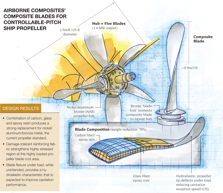
Airborne Composites' Composite Blades for Controllable-pitch Ship Propeller Illustration: Karl Reque
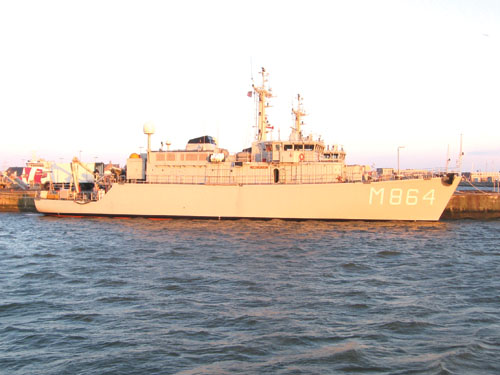
The Royal Netherlands Navy contracted with Airborne International to design a composite alternative to the Alkmaar-class minehunter (pictured) fleet’s existing bronze propellers. Source: Airborne
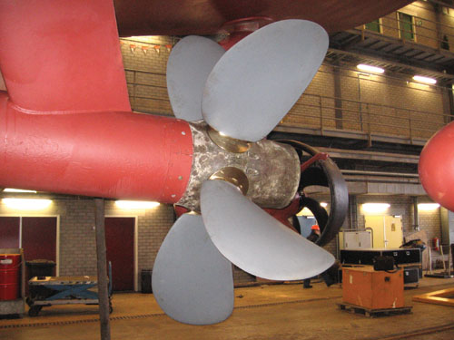
The completed prototype blades are shown installed on a minehunter’s propeller hub. Ongoing sea trials will assess the performance of the propeller, the largest ever produced with composite blades at this power rating. Source: Airborne
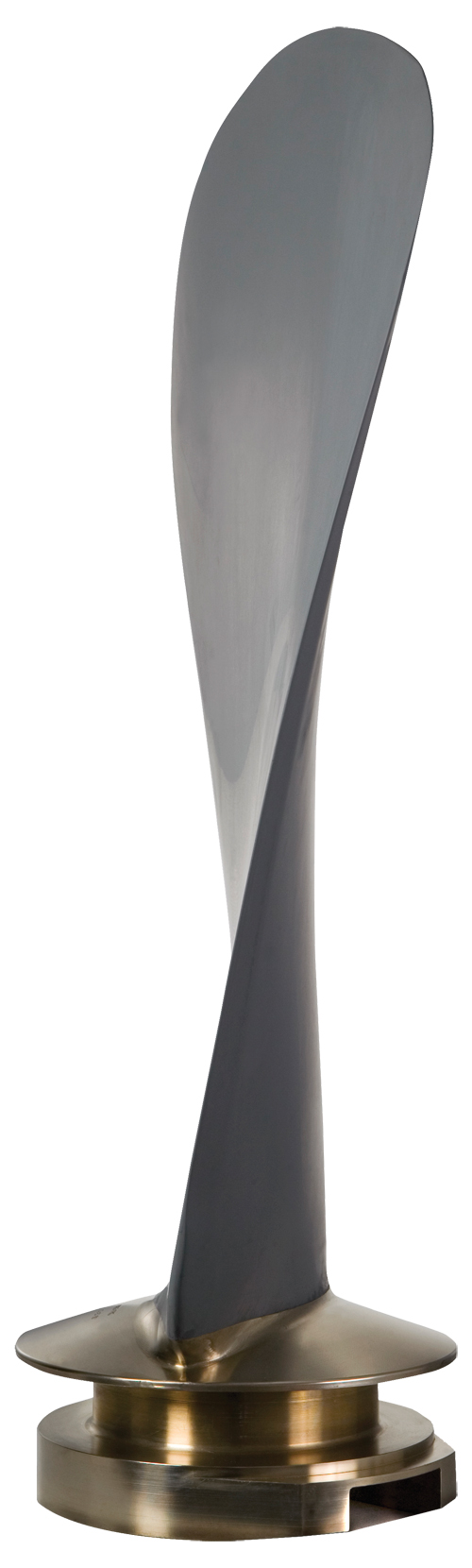
The composite propeller blade, attached to the bronze blade foot that forms the interface with the existing metallic propeller hub. Source: Airborne
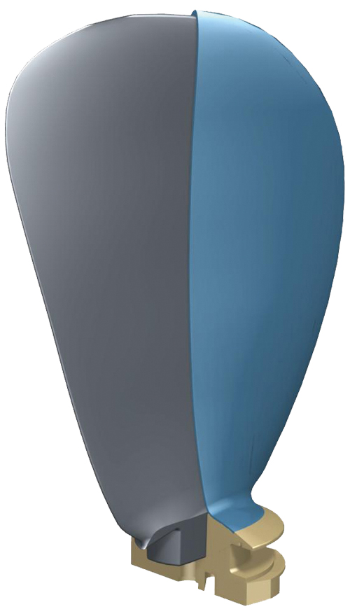
This artist's rendering of the blade shows how the composite blade fits inside the blade foot, as well as the outer polyurethane coating that provides impact-resistance. Source: Airborne


Design Results:
- Combination of carbon, glass and epoxy resin produces a strong replacement for nickel/aluminum/bronze metal, the current propeller standard.
- Damage-tolerant reinforcing fabric strengthens highly stressed region at the highly loaded propeller blade root area.
- Blade flexure under load, while unintended, provides a hydroelastic characteristic that is expected to improve cavitation performance.
When Airborne Composites (The Hague, The Netherlands), a composites design and manufacturing firm, was awarded a contract by the Royal Netherlands Navy (RNLN) in 2004 to develop a prototype composite naval propeller, it faced a complex design brief. The RNLN wanted to explore a composite replacement for metallic propellers on its Alkmaar-class minehunting vessels — ships tasked with the delicate and dangerous job of disarming live mines along hostile coastlines — to decrease the ships’ magnetic, electric and acoustic signatures. Given the potential for improvement in fuel efficiency and a reduction in galvanic hull corrosion, one would think the material swap would be straightforward, but it was anything but, says Airborne Composites’ managing director, Wiard Leenders: “We had to consider multiple variables, including hydrodynamic forces, structural performance of the laminate, corrosion, connection of the blades to the hub and more. In fact, we developed our own computer software interface to investigate and optimize the composite propeller blades for hydrodynamic performance in combination with structural performance.”


Propeller design, considered something of a black art, involves a number of competing variables, including blade surface area, the rake and pitch of the blades in relation to the propeller centerline, and overall diameter. All of these factors affect vessel top speed, fuel efficiency and handling. According to the U.S. Naval Academy, a propeller’s blades act as lifting surfaces, similar to airfoils. As the central hub rotates, each blade produces a pressure differential such that an area of low pressure forms on the forward, or suction, side of each blade, and high pressure results on the back side. The pressure imbalance creates thrust, pushing the propeller and the vessel in the forward direction.
But when the propeller reaches a certain speed, known as cavitation inception speed (CIS), the pressure becomes so low that it drops below the water vapor pressure (for that particular water temperature), causing boiling and subsequent vapor bubbles along the blades, known as cavitation. Cavitation can occur at the blade tips, in “sheets” along the entire blade, or in other forms. The bubbles effectively make the cavitating blade “thicker,” decreasing propeller efficiency. Worse, as the bubbles migrate to the high-pressure region, they implode onto the blade, causing extreme erosive force and damage, similar to a water hammer effect. A damaged propeller is more vulnerable to seawater corrosion, which, in turn, causes more damage and more cavitation. The condition, therefore, worsens with time and increases the acoustic signature of the propeller, a very undesirable situation for a stealthy warship. Cavitation damage affects any propeller material — metal or composite — so Airborne wanted a design that would significantly reduce cavitation potential and keep the acoustic signature low yet not diminish propeller efficiency and hydrodynamic performance, adds Leenders.
A complex design
The RNLN contract specified that the prototype propeller have the same diameter and strength characteristics as the minehunters’ baseline propeller of nickel/aluminum/bronze (NAB) alloy, a commonly used material for naval propellers. NAB has relatively good antibiofouling characteristics, a low magnetic signature, a relatively low corrosion rate and high stiffness compared to other metals. But, its weight is substantial and, eventually, it does corrode particularly when there is cavitation damage, which also leads to vibration and noise. Further, if the ship has a steel hull, NAB can contribute to corrosion elsewhere because it acts as a cathode in the seawater environment and causes the anode (the steel hull) to corrode, even with sacrificial anodes in place near the propeller, forcing frequent inspection and maintenance.
Airborne’s task was to design and build five composite blades that would replace the NAB blades and interface with the existing controllable-pitch NAB hub. The propeller diameter would be 2.5m/8.125 ft, with a power output of 1.4 MW, which would generate considerable force on the blades and the hub connections, says Leenders.
The initial challenge was the blade-to-hub attachment. With the composite prototype constrained to a similar geometry as the NAB propeller, space for the hub connection was limited. After several concepts were evaluated, the Airborne team decided on a bronze “blade foot,” a circular metal part made to fit inside the hub bearing, which has a small, rectangular recess that accepts the composite blade root. A radial bolt secures the blade root in the foot, says Peter Putting, Airborne’s director of operations.
Finite element analysis (FEA) was undertaken to determine the stresses in the blade foot and the blades under operational load conditions, using MSC.Marc from MSC.Software (Santa Ana, Calif.). A modal analysis for vibration response also was conducted. Because the composite blades tended to deform under loads more than metal blades, the deformed geometry was used in the analysis of the propeller’s hydrodynamic performance. Airborne’s experience with other propeller projects, both commercial and military, had led it to develop technology for evaluation and optimization of blade performance. In collaboration with the Maritime Research Institute Netherlands (MARIN, Wageningen, The Netherlands), Airborne designers performed structural FEA analysis on a particular blade design (shape, material and layup), taking into consideration manufacturability, cost, long-term performance and hub interface, and developed a deformation analysis of the blades under load. That information was passed to MARIN researchers, who input the data into their hydrodynamic analysis software. For each blade design, the MARIN software determined performance in the water, given the ship size, including efficiency and cavitation inception. The results were passed back to Airborne for additional iterations and design refinement.
“Due to the short length of the transition zone between the blade foot and the blade itself, the models showed that local stresses — especially shear stresses — in this area were very high, meaning that interlaminar shear was the dominant failure mode,” says Putting. “The root area at the blade foot was found to be the critical part of the design.” To ensure adequate stiffness in the root region and ability to transfer loads between the blades and the hub, a series of tests were developed with a simplified model of the connection to determine the best design approach. Using a similarly sized steel connection as a stand-in for the bronze blade foot, three simplified “beam” layups were tested: a balanced layup using standard epoxy resin; the same balanced layup with a toughened epoxy resin; and a proprietary fiber weave combined with a standard epoxy. The simplified beams were tested in a cantilever arrangement to 100 percent of operational load and then to failure. Although the test samples with stacked layups failed in a brittle manner, the proprietary layup failed at a stress that was 150 percent higher than the failure stress in the stacked layups — well above the operational load — and, therefore, showed a much higher margin of safety.
Based on the models and initial lab tests, Airborne selected a blade structural design that comprises a glass fiber/epoxy core and carbon fiber/epoxy skins, with dry fabrics that account for the stresses at the root. The core and fabrics were assembled in a proprietary layup and infused with epoxy resin. A polyurethane coating, applied to the demolded blades, provides impact protection and reduces algae growth. In keeping with Airborne’s philosophy of efficient manufacturing processes, the blades were designed to be produced to net shape via resin transfer molding (RTM) to reduce postmold finishing.
Blade deformation can be a good thing
Full-scale blade prototypes were subjected to laboratory testing to 120 percent of operation loads. After successful lab results, the blades were delivered to the RNLN in September 2010 and installed for sea trials that will continue through the end of this year, says Leenders.
“The project has definitely shown that a large, controllable-pitch composite propeller is technically feasible,” adds Putting. Indeed, lab tests showed, and on-ship testing, thus far, have verified, that composite propellers have no negative effects on hydrodynamic performance or cavitation-inception properties. Despite the fact that blade deflections under load are greater than those of the NAB baseline, they have no negative effects on hydrodynamic performance or cavitation-inception properties. Notably, propeller weight has been reduced by a substantial 70 percent. Further, cathodic protection measures are no longer necessary to retard hull corrosion, and the nonmagnetic composite increases minehunting safety.
In fact, Airborne reports that the RNLN has been so impressed by the results of the prototype testing that it has commissioned a follow-up study to further investigate the unintended benefits of the more flexible blades, says Leenders. “We wanted to turn the propeller blade deflections into an advantage.”
It turns out that the blade tips change pitch as they bend under dynamic loads, so the tips actually are moving slightly slower than the rest of the propeller when the blades are deflected. Airborne believes, and is conducting computer modeling to verify, that this condition delays the onset of cavitation and leads to quieter operation. In addition, Airborne contends that the pitch change also has the potential to increase ship fuel efficiency by a few percent, which could lead to substantial cost savings in large oceangoing vessels.
“If hydroelastic properties can be designed into a composite propeller,” proposes Peter Coppens, Airborne’s new business development manager, “cavitation can be postponed or possibly eliminated.” Indeed, the company has every intention of pursuing this promising composites application and plans to offer a 5m/16.2-ft diameter propeller in the near future.


Related Content

Assembling the Multifunctional Fuselage Demonstrator: The final welds
Building the all-thermoplastic composite fuselage demonstrator comes to an end with continuous ultrasonic welding of the RH longitudinal fuselage joint and resistance welding for coupling of the fuselage frames across the upper and lower halves.
Read More
Combining multifunctional thermoplastic composites, additive manufacturing for next-gen airframe structures
The DOMMINIO project combines AFP with 3D printed gyroid cores, embedded SHM sensors and smart materials for induction-driven disassembly of parts at end of life.
Read More
Co-molding SMC with braided glass fiber demonstrates truck bed potential
Prepreg co-molding compound by IDI Composites International and A&P Technology enables new geometries and levels of strength and resiliency for automotive, mobility.
Read More
JEC World 2024 highlights: Thermoplastic composites, CMC and novel processes
CW senior technical editor Ginger Gardiner discusses some of the developments and demonstrators shown at the industry’s largest composites exhibition and conference.
Read MoreRead Next

Cutting engine weight via thermoplastic composite guide vanes
Greene Tweed replaces metal stator vanes with its DLF material co-molded with a metal leading edge that meets performance, cost and high-rate production targets while cutting 4 kg per engine.
Read More
Robotic computed laminography brings X-ray CT resolution to large composite structures
Omni NDE collaborative robots, X-ray end effectors and Voxray’s reconstruction approach enables 5-micron inspection of aerospace parts without size constraints.
Read More
Thermoplastic composite materials and processing interactions
Selection of product material formats and their interactions with various process methods heavily influence a final TPC part’s properties and fabrication options.
Read More