
Composite flywheel: HEV racing dynamo
Electric flywheel energy storage system powers Porsche 911 hybrid electric vehicle (HEV) to endurance racing victory.
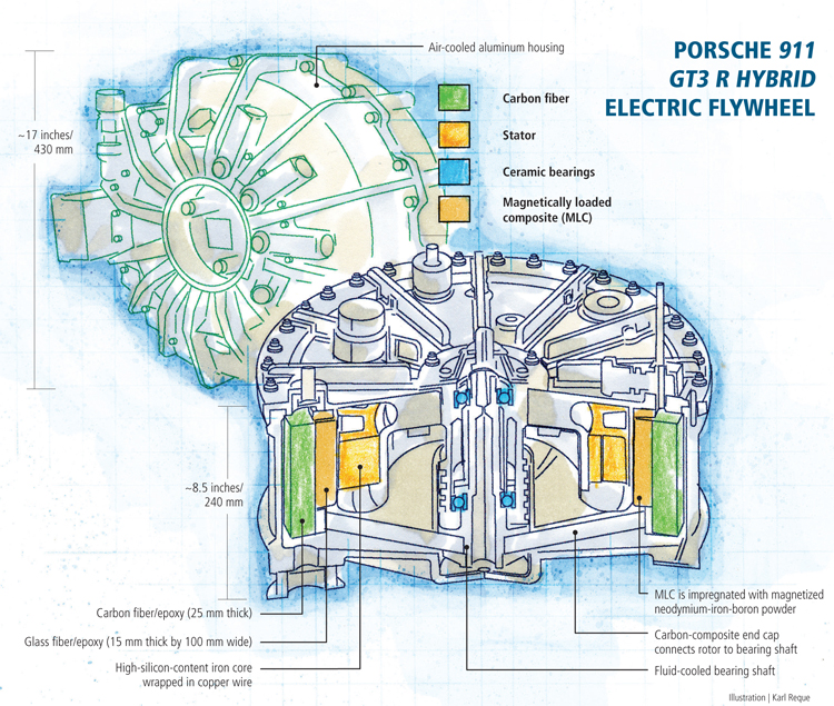
Porsche 911 GT3 R Hybrid Electric Flywheel Illustration: Karl Reque
The glass-fiber/epoxy, magnetically loaded composite rotor is housed inside an air-cooled, aluminum containment structure. The rotor, which also includes a outer carbon-fiber composite layer for reinforcement and mass, rotates at speeds up to 40,000 rpm, creating an electrical current in the copper-coil wound stator at the flywheel’s core. Power is fed to the drivetrain at moments of high demand on the engine. Source: Williams Hybrid Power

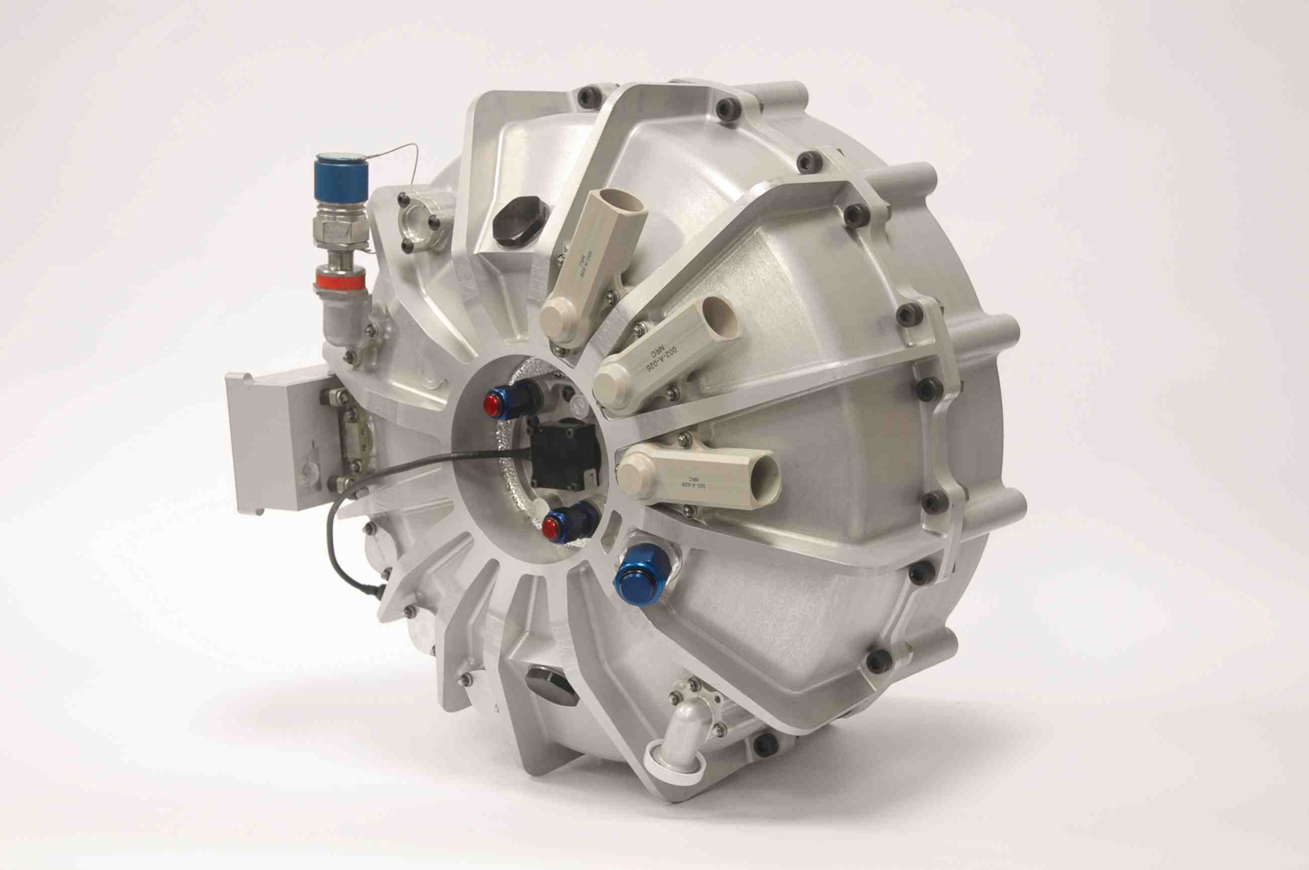
With a WHP flywheel mounted on the passenger side of the cockpit, this 2011 Porsche 911 GT3 R Hybrid took first place in an endurance race in May of this year at the Nürburgring raceway, in Nürburg, Germany. Source: Williams Hybrid Power


Engineering Challenge:
Design a highly efficient, mobile electric flywheel capable of high-density energy storage that can supplement the power of internal combustion engines in hybrid electric vehicles during acceleration or other periods of high energy demand, resulting in fuel savings.
Design Solution:
Make the flywheel’s central rotor from a magnetically loaded glass fiber composite backed by a carbon fiber layer, then mount the rotor in a vacuum, resulting in a flywheel with low eddy-current losses capable of delivering up to 150 kW of power to a vehicle’s drivetrain in short 6- to 8-second bursts.


Around the turn of the 20th Century, scientists successfully quantified the relationship between electricity and magnetism, and engineers soon realized that rotating coils of wire around a magnet, or vice versa, would create a field that could push electrons through metal, producing an electrical current. This gave birth to the first dynamos of the industrial revolution. Dynamos were, and still are, almost always used in a stationary location, that is, fixed to the ground. Today, with the help of composites, the idea of coupling rotational and electromagnetic forms of energy has been given a mobile twist with an electric flywheel energy-storage system installed on a 2011 Porsche 911 GT3 R Hybrid endurance racing car. The flywheel employs a composite rotor that rotates at speeds up to 40,000 rpm to generate, store and deliver power to the car’s drivetrain when additional power is needed — for example, during acceleration — saving fuel in the process.
Nuclear power industry roots
Built by Williams Hybrid Power Ltd. (Oxfordshire, U.K.), the flywheel is an offshoot of technology developed in the 1960s for the nuclear power industry by Urenco Ltd. (Buckinghamshire, U.K.). Urenco had incorporated composite materials in the design of high-speed centrifuges used to enrich uranium. In ongoing research to improve centrifuge efficiency, engineers developed a proprietary method of impregnating glass fiber composites with magnetic powder. Prior to this, ordinary metal magnets were attached to the outside of the centrifuge housing, but they produced significant frictional heat and eddy currents. These currents are induced in a conductor when it is exposed to a changing magnetic field due to relative motion of the field source and conductor. This can cause a circulating flow of electrons — an eddy current — within the body of the conductor. Eddy currents induce magnetic fields that can have repulsive and drag effects on the centrifuge rotor, generating heat and reducing the machine’s operational efficiency.
In the early 1990s, Urenco saw the potential to use these magnetically loaded composite (MLC) materials to build large stationary flywheels designed for specialized short-term energy storage applications. The company formed Urenco Power Technologies to pursue the energy storage market and designed a large stationary electric flywheel unit that weighs approximately 1 metric tonne/2,205 lb, with rotors made of MLC and reinforced with carbon fiber. The company marketed the technology as a Kinetic Energy Storage System (KESS). Stationary KESS units were targeted for two main applications: (1) as a track-side means to store the kinetic energy of an electric-powered commuter or subway train as it comes into the station, then feed the energy back to the train as it leaves the station; and (2) as a means to support and enhance renewable power installations, such as solar and wind, on remote islands by storing energy and feeding it into the grid when renewable power generation fluctuates.
Urenco exited the energy storage market in 2000, but a group of managers at Urenco Power Technologies acquired the rights to the MLC-based flywheel technology and formed a new company, Automotive Hybrid Power. In 2006, engineers at Williams Grand Prix Holdings LLC were researching potential ways to capitalize on a rule change for the Formula 1 racing circuit that would, beginning in 2009, allow cars to have onboard technology for storing and re-using energy. While conducting Internet searches, the engineers ran across Automotive Hybrid Power and its MLC-based flywheels, which were then being developed for racecars. The two companies entered into an agreement to codevelop the flywheel energy storage system for use on Formula 1 cars — a partnership that eventually led to a merger and the formation of Williams Hybrid Power (WHP).
Alex Burns, chairman of WHP and CEO of the Williams Formula 1 team, says the first challenge they faced was adapting KESS technology, modeled on a flywheel affixed to a stationary location, for use in a moving vehicle with quick and frequent accelerations, decelerations and road vibrations. “Designing a flywheel system capable of being reliably used in a mobile race car is very different from the large, static flywheel Urenco had developed,” Burns says.
Critical central rotor
The heart of the company’s electric flywheel is its MLC central rotor. The ring-shaped structure weighs approximately 12.5 kg/27.6 lb and comprises an inner layer of glass fiber/epoxy composite, approximately 15 mm thick by 100 mm (0.6 inch by 4 inches) wide, and an outer layer of carbon fiber/epoxy, of a similar width and a thickness of roughly 25 mm/1 inch (see diagram at right). Neodymium/iron/boron powder is dispersed in the glass fiber composite’s matrix during filament winding. The glass and carbon components of the rotor are wound separately on mandrels and oven-cured. After fabrication, the metal powder in the fiberglass composite is flash-magnetized to produce the desired magnetic field configuration. The cured rotor elements are machined to final tolerance and then the inner MLC and outer carbon/epoxy layers are press-fitted together. The two-layer assembly is housed within an air-cooled aluminum containment vessel, and a carbon fiber-reinforced end cap is mounted at one end of the vessel’s rotational axis. Currently hand-layed and autoclave-cured, it connects the rotor to the bearing shaft at the rotor’s center. The bearings are made of a ceramic material, and the bearing shaft housing is fluid-cooled to ensure the bearings do not overheat. An oil-cooled stator (a high-silicon-content iron core with coils of copper wire wrapped around its outer teeth) is mounted directly underneath the MLC rotor in a stationary position inside the rotor arms. Because the outermost surface of the rotor can reach speeds up to 600 m/sec, a vacuum is maintained inside the vessel to reduce frictional loss from air resistance and prevent the associated heat buildup. The completed flywheel assembly is mounted on the passenger side of the Porsche cockpit.
The flywheel is designed for short-term storage of electrical energy produced by the two electric motors mounted on the front axle of the vehicle. They provide power to the front wheels but double as generators when the car brakes. The produced electricity is fed into the flywheel, causing an increase in the rpm of the rotor. In effect, the flywheel acts as a battery, storing energy in the rotational inertia of the rotor. The electricity generated by the flywheel is fed back to the motors on the driveline during times of high power demand, helping to reduce the overall power demand placed on the vehicle’s internal combustion engine. Gordon Day, operations director at WHP, sums up: “Just as with any common electric motor it can be used as ... a generator to drive electric current,” he says.
The role of the glass-reinforced MLC composite is to induce the electrical current. The carbon fiber outer layer provides structural support for the less robust MLC glass inner layer, and it adds inertial mass to the rotor. As was the case in the uranium-enrichment centrifuges, a primary benefit of using an MLC rotor instead of a magnetized metal rotor is the reduction of eddy currents. Because there are no solid metal magnetic structures in the flywheel’s MLC rotor, eddy current losses are negligible.
Unlike a conventional storage battery, an electric flywheel has a much higher specific power density, which makes it ideal for applications that require relatively short bursts of energy at a higher power (greater than 90 kW). The downside, however, is it has a lower overall energy density. That is, its storage capacity is very short term because it is entirely dependent on the latent power in the rotating flywheel (when the rotation slows or stops, so does its storage potential). Therefore, flywheels are unlikely to replace conventional batteries in applications that require long-term energy storage. But an electric flywheel is an ideal supplement to conventional batteries in hybrid energy storage architectures.
The redesign of the flywheel used on the 2011 Porsche resulted in a 25 percent boost in available power, from 120 kW to 150 kW. That, in turn, translates to a nearly 50 percent power boost to the internal combustion engine. Day says design changes that accounted for increased power of the 2011 flywheel included improved cooling of the stator and containment structure as well as an overall weight reduction of 20 percent.
On track for future performance
WHP first tested a prototype MLC flywheel in a Formula 1 racecar in 2009. This initial design was modified and adapted for use in the 2010 Porsche 911 GT. Since the new flywheel hit the racing circuit, Porsche reports a 10 percent increase in fuel economy, which in endurance racing translates to fewer refueling stops. A flywheel-equipped 2011 Porsche 911 GT3 R Hybrid achieved its first victory in May of this year, finishing first in the fourth round of the VLN Endurance Racing Championship at the Nürburgring (Nürburg, Germany). Day adds that a modified version of the flywheel will be demonstrated on a bus next year, most likely in London. “As a high-power-density energy storage for KESS hybridization, the technology has the potential to deliver significant fuel savings for high-duty, start/stop transportation, such as city buses,” Day says.


Related Content

Post Cure: 3D printed plastic, composite mouthstick designs assist limited-mobility users
Three M Tool and Machine has used its in-house additive manufacturing capabilities to rethink medical devices like mouthsticks, which must be stiff, lightweight and comfortable enough for everyday use.
Read More
Prepreg compression molding supports higher-rate propeller manufacturing
To meet increasing UAV market demands, Mejzlik Propellers has added a higher-rate compression molding line to its custom CFRP propeller capabilities.
Read More
Bladder-assisted compression molding derivative produces complex, autoclave-quality automotive parts
HP Composites’ AirPower technology enables high-rate CFRP roof production with 50% energy savings for the Maserati MC20.
Read More
Exel Composites adopts bio-based UPR resin at commercial scale
Purchase of Polynt bio-based resin delivers 20% cut in CO2 footprint for composites manufacturers, builds Exel’s efforts to give customers more sustainable options.
Read MoreRead Next

Dialing in composites performance via dynamic digital twins
Sport Dynamics Lab uses Flexdynamics testing, digital models and AI tools to compare designs, materials and systems, enabling optimization with potential for propellers, drones and vibrational structures.
Read More
Post Cure: 3D printed plastic, composite mouthstick designs assist limited-mobility users
Three M Tool and Machine has used its in-house additive manufacturing capabilities to rethink medical devices like mouthsticks, which must be stiff, lightweight and comfortable enough for everyday use.
Read More
Industrial ultrasonic NDT adaptation permits accessible composite bicycle inspection
Cycle Inspect's ASNT-aligned certification program employs affordable twin-crystal ultrasonic testing equipment and standardized inspection methods to detect damage in composite bicycle components.
Read More