
Composite design selected for salmon tracking antenna
Tough and affordable ultrathick laminate the solution for fish counting application.


Source: Illustration: Karl Reque
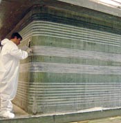
Source: USACEAn aluminum template guided accurate routing of slots in the laminate, in which the antenna's copper wire coils were embedded. Plexus adhesive was used to secure the wires in the routed grooves.
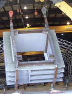
Source: INTECThe completed fish counter antenna, showing the grout chamber flanges and inner wear strips attached. The part is being lifted by crane onto a transport barge.
When demanding applications call for unique solutions, composite materials are often the answer. Such was the case for the U.S. Army Corps of Engineers (USACE), working with the Bonneville Power Admin. to allow thousands of juvenile salmon safe passage through a 4.6m/15-ft wide channel that bypasses Bonneville Dam in Washington State.
A recent federal court ruling requires more spending for fish management, to ensure better survivability. USACE wanted to be able to accurately and quickly count the number of fish that pass the dam, using passive integrated transponders, or PIT-tags -- a relatively new radio frequency identification (RFID) method. Hatchling salmon are injected with a tiny, patented microchip, the brainchild of Digital Angel Corp. (Minneapolis, Minn.). The challenge was to construct a tag reader device, or antenna, that could identify the embedded microchip in each fish as it passes by at water velocities up to 12.2m (40 ft/sec). Digital Angel designed the antenna's electronics, while a team that included composites testing and design firm Integrated Technologies Inc. (INTEC, Everett, Wash.) and large boat fabricator Northern Marine (Anacortes, Wash.) developed the composite design and built the prototype part.


"Under our Memorandum of Agreement with the Bonneville Power Admin., the Corps is responsible for installing PIT-tag detectors at our facilities," says USACE's Jeff Hurt, the project engineer. "Most are much smaller, on the order of a few feet, but the size of this part was dictated by the size of the channel it's going into -- it's a quantum leap in terms of size for this sort of application."
To meet the project's objectives, the antenna was designed as a massive, ultra-thick, 457mm/18-inch solid fiberglass laminate, in the shape of a square box culvert through which the fish swim. The culvert is 2.8m/9 ft long and 5.5m high by 5.5m wide (18 ft by 18 ft) and weighs 49,895 kg/110,000 lb. Four projecting flanges, called grout chambers, extend approximately 0.3m/12 inches beyond the outside perimeter of the solid laminate core. The flanges were designed to position the antenna within the channel, contain the concrete that will be poured around the part, and help support an electromagnetic shield around the part. The shield is simply four large aluminum plates welded together, explains Hurt. During antenna operation, the plates will contain the electromagnetic field generated by multiple loops of copper wiring, encased within the monolithic laminate. When electronic testing is completed, the antenna will be placed within the Bonneville Dam's bypass collector channel.
A VERY ROBUST DESIGN
The primary design driver was electromagnetic transparency, which eliminated a metallic structure. Secondly, the structure had to be completely watertight, so that moisture would not interfere with the electrical current moving through the embedded copper wires, which meant a structure with very low porosity. The wires had to be placed precisely 152 mm/6 inches away from the inside (or wetted) surface of the antenna, the specified distance for tag detection. The hefty laminate thickness was required to withstand the hydrodynamic loads imposed by the swiftly moving water, and to damp any vibration that could potentially disrupt the electromagnetic field if floating debris hit the antenna. "The part had to be very robust and durable, because this is a high-friction environment with a lot of floating logs," says Hurt. "It's a challenging environment, to say the least."
INTEC performed the laminate design. Northern Marine was chosen to fabricate the antenna, based on its experience with large parts. While USACE did consider other materials, including nonmagnetic epoxy-based polymer concrete, INTEC's Robert La Mantea says that the concrete would have been too porous, allowing water ingress, and not strong enough to handle the loads that would be imposed on the part during installation. "The solid fiberglass laminate was, by far, the best way to go for this application, despite the part's large size," says La Mantea. "The challenge was to select the right materials and the right manufacturing method to produce it."
The laminate was much too thick to be fabricated in one shot, because of the danger of uncontrolled exotherm. Designers opted to go with vacuum-assisted resin transfer molding (VARTM) and build up the thickness in a series of layup, infusion and cure cycles. Northern Marine fabricated test panels with embedded thermocouples to determine the optimal thickness that could be layed up in one cycle without excess exotherm. Northern Marine's Slade Bedford, who supervised the project, says that a crucial part of the test was ensuring that the dry stack would not slump when layed up on vertical surfaces. "We determined that the optimum thickness was 70 mm/2.75 inches," he says.
To accommodate the antenna wiring, the laminate stack would be built up to a thickness of 136.5 mm/5.375 inches, then at least 30 closely spaced, circumferential grooves would be routed with a diamond router bit, to a depth of 9.5 mm/0.375 inch, to hold the copper coils. An aluminum template, cut with a waterjet, was used for proper positioning of the grooves. Accuracy of the wire placement was critical for operation of the electromagnetic field within the antenna, and the grooves could only deviate by 3.2 mm/0.125 inch. Plexus methyl methacrylate adhesive, supplied by ITW Plexus (Danvers, Mass.), was selected as a filler/potting adhesive to hold the wires in place within the routed grooves. After complete cure of the adhesive, Northern Marine would continue to build up the laminate to the full 457-mm/18-inch thickness.
Hurt wanted the part to be repairable, in case a large object damaged the inside of the culvert. Therefore, the design included separately fabricated, 25.4-mm/1-inch-thick fiberglass/vinyl ester wear plates. The plates, a few inches longer than the part length, would extend beyond the opening, bonded to the inside surfaces of the part with Plexus adhesive. If laminate damage were to occur, the plates could be spot-repaired or, if necessary, ground down and replaced. "Composites are somewhat susceptible to abrasion," says La Mantea. "The wear strips are a great idea for affordable repair."
MULTIPLE LAMINATION CYCLES
Once testing was complete, Northern Marine constructed a rectangular, 4.6m by 4.6m by 2.8m (15-ft by 15-ft by 9-ft) layup mandrel (the inside dimensions of the antenna). The layup surface was created with sheets of medium-density fiberboard (MDF) butted and glued together. Timber-strand board on 152-mm/ 6-inch centers formed the internal framework that supported the MDF surface panels. The MDF was coated with a layer of Duratec vinyl ester mold surfacing material, from Hawkeye Industries Inc. (Marietta, Ga.), and then treated with a wax mold release supplied by TR Industries (South Gate, Calif.).
The fiberglass was a heavy-duty, 0°/90° 108-oz stitched E-glass fabric supplied by Vectorply Corp. (Phenix City, Ala.), chosen for maximum fiber content and fast buildup of the thick laminate. Northern Marine custom-formulated the infusion resin, beginning with a vinyl ester base resin (781-2140) supplied by Resolution Specialty Materials (formerly Eastman Chemical, Carpentersville, Ill.) and adding a mix of inhibitors and accelerators. The modifications increased the resin's gel time, limited exotherm and established a suitable viscosity for infusion, explains Bedford.
"We decided to use vinyl ester because we use it for our boat hulls and are familiar with it," says Bedford. "The antenna is going to be placed in a very harsh environment, and vinyl ester has the performance characteristics -- higher strength, corrosion resistance and mechanical properties -- that meet the conditions."
Once the first few laminate stacks, including integral upper and lower flanges, were completed using standard vacuum infusion methods, the mandrel was removed, because the part was by then self-supporting and able to act as its own layup tool for the subsequent layers, explains Bedford. At the specified thickness of 137 mm/5.375 inch -- the required distance for placement of the wires, minus the thickness of the wear plates -- workers began routing the grooves. According to Bedford, this was one of the most daunting aspects of the entire project. "The infused laminate was very hard, with a fiber/resin ratio of 60/40," he notes. "We went through a lot of router bits, needless to say."
At this point, the inner grout chambers were formed by adding two additional flanges made on a separate tool, then bonded onto the grooved laminate stack. In order to build up the remaining thickness between the flanges, Northern Marine decided to infuse laminate "billets" offline. The billets, layed up on flat tables, were [6.4m long by 0.91m wide by 152 mm thick (21 ft by 3 ft by 6 inches), each produced in one infusion cycle. Bedford says that the single shot was possible because the billets were layed up flat. When cured, the billets were trimmed to size with a waterjet cutter and then bonded onto the structure with Plexus adhesive to achieve the full part thickness. A final single 19 mm/0.75 inch ply of 0/90 cloth was then infused over the billets and the flange bond lines to tie the entire part together. The inch-thick wear plates were then fabricated and cured separately on layup tables, and bonded to the inside of the structure and finished by brushing on a layer of Duratec surfacing material, for extra durability. Fibrebolt composite fasteners produced by Strongwell (Bristol, Va.) will be used to bolt the aluminum shield to the part.
TESTING UNDERWAY
The massive antenna was loaded by crane onto a barge and transported upriver to the dam in mid-2004. Digital Angel is currently testing the system on Cascade Island. Hurt says the installation schedule depends on the results of the electrical testing. "There's a physics problem in creating an electromagnetic field that's strong enough to turn on and track the tags," he explains. "At this large size, it's taking a while for the system to work -- we're really doing research and development here."
With luck the antenna will be emplaced in mid-2005. If successful, the technology holds promise for wider use where environmental monitoring is required. La Mantea concludes, "The composite part itself is a success and demonstrated an affordable alternative for the project."


Related Content

Composites end markets: Sports and recreation (2025)
The use of composite materials in high-performance sporting goods continues to grow, with new advancements including thermoplastic and sustainability-focused materials and automated processes.
Read More
Partners recycle A350 composite production waste into adjustable-length rods for MFFD
Herone, Spiral RTC, Teijin Carbon Europe and Collins Aerospace Almere recycle A350 thermoplastic composite clips/cleats waste into rods for the all-thermoplastic composite Multifunctional Fuselage Demonstrator’s crown.
Read More
Plant tour: Hexagon Purus, Kassel, Germany
Fully automated, Industry 4.0 line for hydrogen pressure vessels advances efficiency and versatility in small footprint for next-gen, sustainable composites production.
Read More
Biomaterials make strides toward composites sustainability
A compilation of trends in development or application of natural fibers, bio-based resins and more showcases industry players, educational institutes and global projects.
Read MoreRead Next

Cutting engine weight via thermoplastic composite guide vanes
Greene Tweed replaces metal stator vanes with its DLF material co-molded with a metal leading edge that meets performance, cost and high-rate production targets while cutting 4 kg per engine.
Read More
Composite trends gaining industrial traction for 2026
Startups & Investors topics over the last year show the industry is rapidly gaining maturity while benefiting from macro-trends in circularity, AI and TPC and high-rate manufacturing, all potential gains for investors.
Read More
Thermoplastic composite materials and processing interactions
Selection of product material formats and their interactions with various process methods heavily influence a final TPC part’s properties and fabrication options.
Read More