
Carbon composite driveshaft: Tailorable performance
This racing and aftermarket specialist designs and produces custom driveshafts for multiple markets.

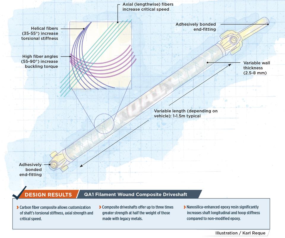
QA1 Filament Wound Composite Driveshaft Illustration: Karl Reque
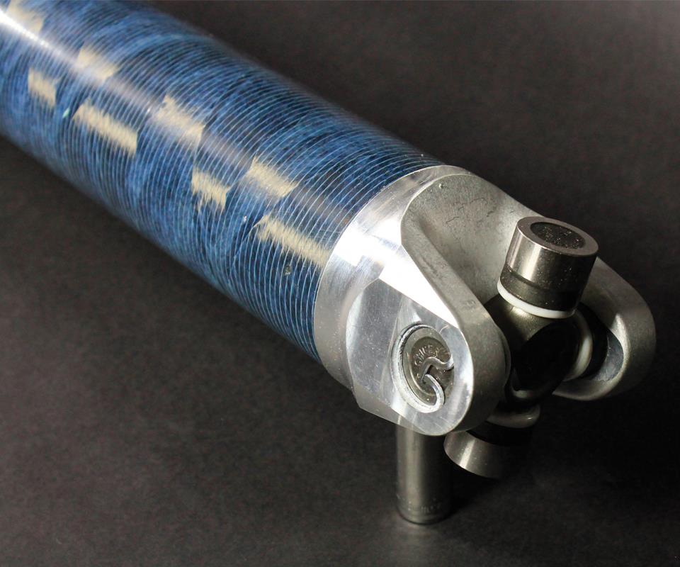
Lighter and stronger than metals. An all-composite, lament-wound driveshaft fabricated by QA1 (Lakeville, MN, US) is commonly three times stronger at half the weight than a metallic version. Custom metallic end- fittings, appropriate to a specific vehicle type, are attached to the ends of the composite shafts in a proprietary 11-step bonding process. Source (all photo): QA1 Precision Products
Critical: Winding pattern + material selection. The design process considers multiple performance factors to optimize the fiber winding pattern. QA1 employs a modified epoxy resin that contains silica nanoparticles, supplied by 3M Aerospace and Commercial Transportation Div. The additive significantly increases shaft longitudinal and hoop stiffness and delivers higher abrasion resistance, compared to conventional epoxy resin systems.
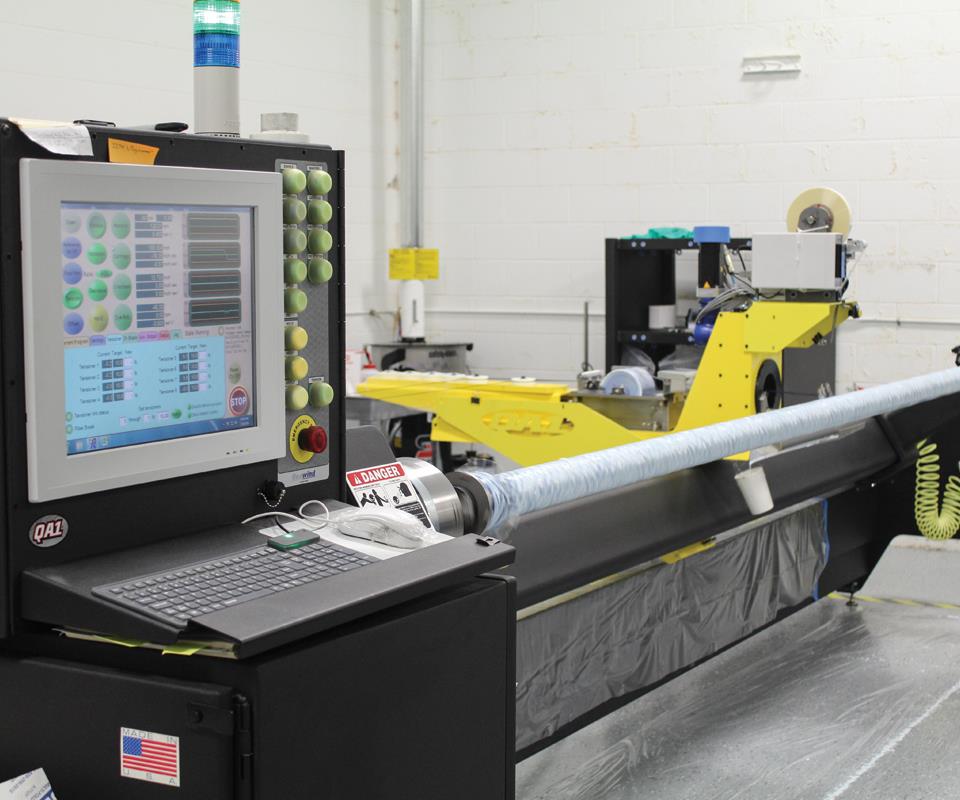
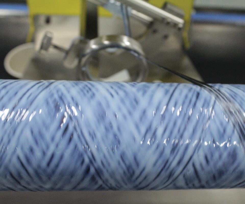
Wound, inspected and tested with care. Driveshafts are produced on a McClean Anderson-supplied lament winding machine, and oven-cured in-house. Each driveshaft undergoes microscopic inspection, mechanical testing and torsion testing, before delivery.
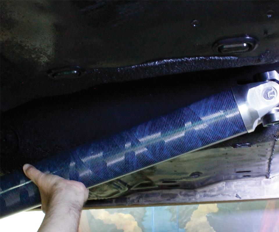
Market focus: Performance upgrades. An all-composite, lament-wound driveshaft fabricated by QA1 is installed in a performance car, replacing a metal driveshaft.


Every gearhead knows that the transfer of power from an engine to the axle and drive wheel in a rear-wheel drive vehicle requires a driveshaft, and that this highly loaded part is typically made of steel or aluminum. When composites became more widely available in the early 1980s, carmakers recognized that a carbon fiber composite driveshaft could bring significant benefits unavailable with metal designs, and several production vehicles were so equipped through the early 2000s (see “Composite driveshafts in production vehicles"). Nevertheless, OEMs never fully embraced composite driveshafts, due to shifts to front-wheel-drive cars (which don’t need driveshafts), four-wheel drive vehicles (which use shorter shafts, for which metals suffice) and the always-present composite/metal cost differential.
Yet, in some corners, composite driveshafts never went away, and there are numerous manufacturers who have prospered making shafts for race cars, hot rods and specialty applications. One of these is QA1 Precision Products Inc. (Lakeville, MN, US), founded in 1993. A specialist in driveshafts, QA1 also turns out bearings, suspension elements and shock absorbers for the full gamut of racing disciplines. “The technology governing composite driveshafts is better today, not just in materials but also in faster manufacturing and assembly,” asserts Travis Gorsuch, QA1’s director of advanced materials. “Composite shafts offer many benefits.”


Custom designs for customer applications
In a nutshell, several performance factors interact in driveshaft design. Basically a thin-walled hollow tube, a driveshaft must have adequate stiffness to resist buckling under a specified engine torque output, which might be, for example, 2,500 lb-ft in a high-end, 500-cubic-inch race engine turning at 8,000 rpm. Although the universal joint connections at each end of the driveshaft relieve much of the stress in the drivetrain due to the changing angles, the shaft must perform well because the rear axle constantly moves in relation to the engine. And perhaps most important to the design, the driveshaft must be stiff enough that its natural resonant frequency is higher than that of the engine and the rear axle, so that it does not create destructive resonant vibration. at is, critical speed — the point at which the driveshaft’s rotational speed and its natural frequency coincide, augmenting vibration to the point of instability — defines the frequency of the first order bending mode. At this point, the driveshaft will undergo amplified displacements, which can cause the shaft to bend or even whip, and ultimately destroy itself. Damping strategies to control first-order vibrations can be employed, to take advantage of the higher frequencies between the second, third, fourth and higher resonances.
Gorsuch’s team addresses these performance factors with a combination of computer modeling, laboratory tests and in-vehicle, on-track testing of driveshafts, for a range of specific applications. “We look closely at each market and develop specific performance goals, whether it is high critical speed, high torque, weight or perhaps durability, and create custom products for each.” He cites the example of QA1’s driveshaft for dirt track race cars, for which high buckling strength and durability are over- riding concerns. Another product targets street racers who favor much larger engines that produce higher torque, which overpower factory-supplied, two-piece steel driveshafts. Customers also can request a custom-made driveshaft for their specific requirements.
Beginning at square one
To produce a driveshaft, QA1’s engineers first input a customer’s information — car type, engine type, horsepower and torque, rpm limit, automatic or manual transmission, type of rear suspension setup, and more — into the company’s design process. According to Scott Neubauer, QA1’s composites engineer for advanced materials, QA1 calculates 12 engineering constants for the thin-walled, tubular driveshaft laminates via a numerical model that is based on a three-dimensional implementation of classical lamination theory. The constants are the elastic moduli (Ex, Eθ, Er), the shear moduli (Gxθ, Gθr, Gxr) and the Poisson’s ratios (Vxθ, Vθr, Vxr, Vθx, Vrθ, Vrx).
“Out of these 12 constants, we use the three elastic moduli and three shear moduli to calculate buckling torque, critical speed, torsional stiffness, and torsional frequency — the latter is a recent addition that is still being validated. All 12 of the constants are used in generating laminate-wide stress/strain responses from various directional loads,” explains Neubauer.
The software used for all infinite element analysis (FEA) and inertia calculations is SolidWorks Simulation, supplied by Dassault Systèmes SolidWorks (Waltham, MA, US). Says Neubauer, “We also use a numerical model that is implemented in Microsoft Office’s native scripting language, Visual Basic for Applications (VBA). This allows us to take advantage of Excel’s solvers [Evolutionary, GRG-Nonlinear, Simplex LP] to generate optimized laminates given certain criteria.” Modal analysis also is conducted to determine natural frequencies and thus the minimum required shaft stiffness. Ultimately, the design process produces fiber winding patterns, tube diameter and wall thickness for a customer’s specific requirements and performance factors. Although the winding patterns and ply sequence used for each customer or market application are strictly proprietary, generally, the following parameters apply: Axial (0-35°) fibers tend to increase critical speed; helical winding angles of 35-55° tend to increase torsional stiffness; high fiber angles of 55-90° (hoop) tend to increase buckling torque.
A lower winding angle of 20-30° might be chosen if torsional “softness” would be desirable, that is, the shaft would allow a slight axial twist to withstand abrupt power input. “The combination of our design software tools allows us to go through an iterative development process fairly quickly,” adds Gorsuch, “and we can design, fabricate and test shafts in a relatively short period, to confirm our computer modeling.” He adds that QA1’s driveshaft designs are symmetrical with balanced layups, to ensure even stress distribution and balance, with wall thicknesses ranging from 2.5 to 8 mm.
Nanotech for better performance, big benefits
QA1’s design efforts, however, go beyond careful attention to the critical reinforcement. “The axial and hoop moduli of a shaft are dependent not only on the winding pattern, but also on the resin matrix modulus,” Gorsuch points out, “which strongly affects lamina transverse and shear stiffnesses.”
QA1 has worked closely with 3M Aerospace and Commercial Transportation Div. (St. Paul, MN, US) to test and develop a version of 3M’s 4831 epoxy, which contains silica nanoparticles, for all of its products. Gorsuch says the nanosilica, added at 30-40 wt/%, significantly increases shaft longitudinal and hoop stiffness for a fixed winding pattern, fiber type and fiber content, and it also produces a more durable product with greater abrasion resistance than one made with an unmodified resin.
QA1 typically uses T700 standard-modulus polyacrylonitrile (PAN) carbon fiber from Toray Carbon Fibers America Inc. (Flower Mound, TX, US), but other fiber types are always under evaluation, including those from Mitsubishi Rayon Carbon Fiber and Composites Inc. (Sacramento, CA, US), DowAksa USA (Marietta, GA, US) and Hyosung Corp. (Seoul, Republic of Korea).
Gorsuch adds that the company has researched the use of high-stiffness, pitch-based carbon fiber, as well as combining fibers of different moduli in a single part, but, he adds, “while it helps to increase performance, it becomes difficult since it adds manufacturing cost.”
After a lament-wound shaft is completed on the company’s McClean Anderson LLC (Schofield, WI, US)-supplied lament winding machine, it is wrapped with compaction tape and oven-cured in QA1’s custom oven, built in-house for tailorable ramp and dwell cycles. After cure, a shaft is cut to length and a small piece is cut from one end, which undergoes microscopic inspection, using Olympus Stream image analysis software, from Olympus Corp. (Waltham, MA, US), to validate fiber volume, fiber angle and void content. “With this image analysis software, we can verify that the void and fiber volume meet our specifications. In addition, we verify layer thickness and fiber angle,” says Gorsuch.
The image analysis inspection is followed by mechanical testing, then metallic end fittings are attached, via QA1’s proprietary 11-step bonding process. Next, shafts are torsion tested in house, says Gorsuch: “This is a very vital part of our process, and allows us not only to validate our FEA modeling by showing that a shaft performs as modeled and that simulations are appropriate, but also to ensure the quality of every driveshaft we produce.” For specific markets, the testing certifies that driveshafts meet racing quality assurance overseer SFI Foundation Inc.’s (Poway, CA, US) driveshaft specification 43.1. This is followed by a balancing test, to ensure no vibration at operational speeds.
“Our designs are commonly three times stronger than a metallic shaft, and come in at about half the weight,” asserts Gorsuch. That alone is a huge benefit: Overall vehicle weight and engine power loss from rotating a heavier metallic shaft are significantly reduced, with no impact on performance. But there’s more. From a safety standpoint, the composite will splinter upon impact in the event of a crash, preventing additional damage to the vehicle and its occupants. That’s not the case with a metallic shaft, Gorsuch adds, which can fail catastrophically. Last, but not least, composites offer better corrosion resistance.
Concludes Gorsuch, “Drivers want more in their cars today, and a lighter driveshaft reduces rotating weight and overall vehicle weight. I believe there’s a trend toward greater adoption of composite driveshafts.”
See “Composite output shaft ready for automotive proving ground” for more on the design of a filament-wound automotive output shaft.


Related Content

CFRTP upper stage propellant tank
PROCOMP uses in-situ consolidation AFP and ultrasonic welding to demonstrate lightweight, novel tank design.
Read More
Digital design, multi-material structures enable a quieter supersonic NASA X-plane
NASA’s composites-intensive X-59 QueSST experimental aircraft is set for its first flight by the end of 2022, after nine years of design, manufacture, assembly and testing by Lockheed Martin Skunk Works.
Read More
Thermoplastic composites: Cracking the horizontal body panel nut
Versatile sandwich panel technology solves decades-long exterior automotive challenge.
Read More
Next-generation airship design enabled by modern composites
LTA Research’s proof-of-concept Pathfinder 1 modernizes a fully rigid airship design with a largely carbon fiber composite frame. R&D has already begun on higher volume, more automated manufacturing for the future.
Read MoreRead Next

Composite output shaft ready for automotive proving ground
Unlike automotive driveshafts, automotive output shafts cannot leverage shaft length as a factor when making the case for composites. Instead, other beneficial features have made a composite output shaft able to compete with metal shafts, especially in electric vehicles.
Read More
OOA: Thermoplastic alternative targets performance spec
CF/PEEK helicopter driveshaft’s toughness trumps traditional metric.
Read More
CW’s 2024 Top Shops survey offers new approach to benchmarking
Respondents that complete the survey by April 30, 2024, have the chance to be recognized as an honoree.
Read More