
Bridge cost cut with inflatable arches
Stay-in-place composite formwork shortens installation, doubles service life of concrete bridge structure.

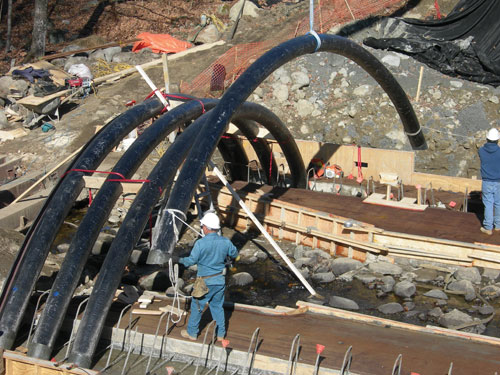
The fourth of 23 tubular composite arches for the Neal Bridge replacement, each with a diameter of 12 inches/31 cm, is lowered into position over the formwork. Source: UMaine
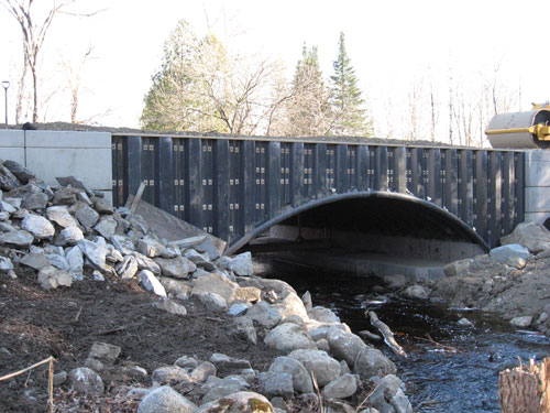
The finished bridge structure, with composite spandrel walls in place to contain the sand-filled backfill, awaits paving and placement of guardrails. The 35-ft-long by 44-ft wide (11m by 13m) span was installed in only three days. Source: UMaine
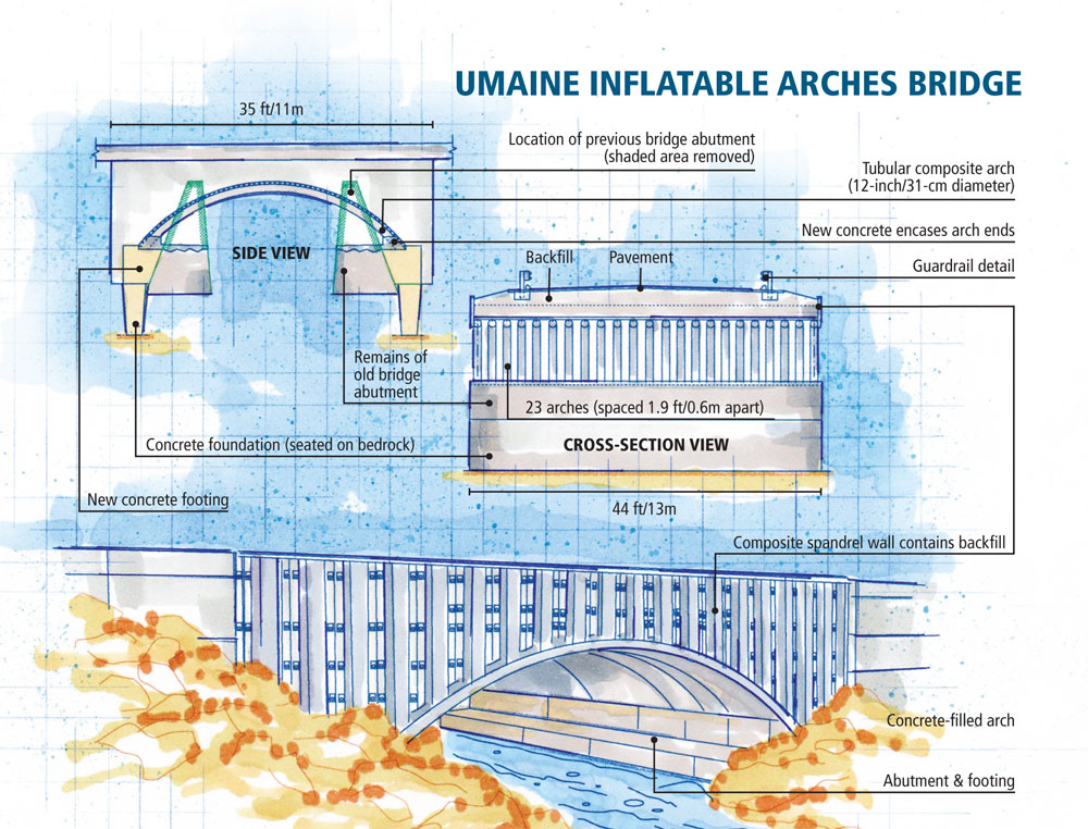
Illustration: Karl Reque
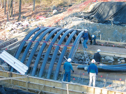
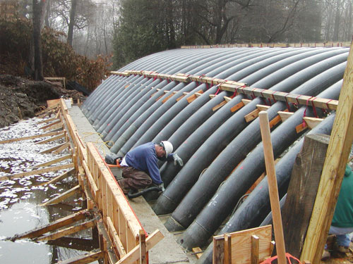
Here, installers check the spacing (1.9 ft/0.6m) between arches 7 and 8. When all 23 were secured, their ends were encased, on each side of the stream, in shallow concrete footings. Source: UMaine
With all 23 arches in place, structure is ready for decking, which will be fastened over the upside of the arch curve. Source: UMaine


Engineering challenge:
Devise a concrete bridge design that vastly reduces the cost and time expended for hand-assembled wooden forms and rebar, and mitigates the effects of environmental deterioration.
Design solution:
Replace conventional formwork with inflatable composite sleeves that are filled with Portland cement-based concrete, covered with decking and then surfaced, providing a low-maintenance, rebar-free bridge system.


Steel-reinforced concrete is a relatively inexpensive and, when properly cured, very strong, stiff and durable building material. But in bridge structures, it has proved problematic. Concrete is subject to chemical attack by road salts and other deicers. If these substances, mixed with water, enter cracks in the structure, temperature-induced expansion and contraction and the corrosion of rebar can cause spalling and premature loss of structural integrity. Additionally, cast-in-place concrete requires that extensive formwork be built on site and can’t be poured and cured in cold or wet weather. Although the use of precast concrete can abbreviate installation and prevent weather delays, precast pieces are extremely heavy and, therefore, costly to move and install. Further, the need for heavy equipment and large work crews can trigger environmental impact studies that delay project starts and inflate bridge costs.
The University of Maine’s Advanced Structures & Composites Center (UMaine, Orono, Maine) has spent eight years seeking remedies for these challenges. That work yielded its first practical result when the Maine Dept. of Transportation (M-DOT) recently replaced a 70-year-old concrete bridge in nearby Pittsfield, with one built on inflatable composite arches, a design that addresses all the issues that currently prolong a conventional concrete bridge installation and shorten the resulting structure’s service life.
“We were looking for ways to use … composites … to reduce the time it takes to erect formwork or, better yet, get rid of it — and rebar — altogether,” recalls Center director Dr. Habib Dagher of the program’s beginnings. “Plus, we wanted to find a way to protect concrete from the environment.”
Reinventing the concrete bridge
The university assembled a team to pursue these goals in the context of an arched structure (considered to be the most efficient for bridges) that could be produced at the work site. Among the large number of design options considered and then discarded were rigid foam-backed forms and composite overmolding, using “tools” like bent thermoplastic tubes.The concept that showed the most promise for formwork was an array of fabric sleeves that could be inflated and then made rigid by applying and curing a thermoset resin. In theory, it would serve as a stay-in-place concrete form, an exoskeleton that eliminates the need for rebar and a waterproof layer to protect the concrete from environmental deterioration, but it proved to be very challenging in the realization. Years were devoted to fiber architecture alone — finding the right types and orientations of fibers to handle the hoop stress (to contain the wet concrete), biaxial shearing forces, and longitudinal stresses. Other questions concerned the most efficient methods for producing the sleeves and introducing concrete into them, as well as how to ensure they would be watertight and that fiber buckling on the inner curve when the sleeves were formed into arches wouldn’t sacrifice mechanical properties.
In final form, the sleeve fabric is a complex and proprietary blend of glass, carbon and other unnamed fibers. The custom-designed sleeves are cut to length and width, joined in a proprietary manner to form a tube and mounted on custom-built fixtures. Next, the tube ends are sealed, the sleeves are inflated with air, and then they are impregnated with resin. Curing occurs at room temperature and normal atmospheric pressure. According to Dagher, tube length, diameter, wall thickness and the number of arches can be varied to accommodate the needs of any given application. Longer, larger-diameter arches placed closer together can carry higher loads.
UMaine also had to custom-formulate a durable, ductile resin that would adhere well to concrete and develop a proprietary self-consolidating Portland cement-based concrete that expands slightly to ensure a continuous bond between it and the composite shell.
Data collection & mathematical modeling
When the design and materials were set, the team built scale models and eventually full-size structures in the university’s 35,000 ft² (3,252m²) lab (soon to be expanded to 60,000 ft²/5,574m²). Dozens of arches were produced in 20-ft, 35-ft and 60-ft (6.1m, 11m and 18m) sections and subjected to a variety of tests, including static and fatigue testing, environmental cycling, and UV exposure.Accelerated fatigue testing subjected the concrete-filled arches to the equivalent of 50 years of truck traffic over a busy interstate bridge. Afterward, the arches retained their full load-bearing capacity — residual strength was equivalent to initial strength. Testing also revealed that, compared to reinforced concrete, the arches are extremely ductile, a function of confinement of the concrete and elimination of rebar. (If the bridge exceeds its design stresses and the rebar is put into compression, it can buckle outward, fracturing the concrete.) The arches effectively form three plastic hinges (constrained at both ends and at the top) and maintain peak strength throughout fatigue testing. Adverse environmental testing has shown that the arches are effective at the temperatures at which conventional concrete bridges are used, that is, from -30ºF to 150ºF (-34ºC to 66ºC).
The team used the test data to build mathematical models for now-patented virtual prototyping (CAE) tools that help optimize bridge design. The software calculates arch span and elevation, the number and spacing of arches required by the expected loads, and the diameter and thickness of the composite sleeve, and then it predicts failure and fatigue behavior.
Putting it together in Pittsfield
During a tour of the university’s composites lab a year ago, Gov. Baldacci and members of the Maine legislature were so impressed with the arches technology that the governor’s office and M-DOT developed a Composite Bridge initiative to promote the use of composites in the state’s infrastructure. M-DOT found a candidate for a full-size demonstrator in the 35-ft long by 44-ft wide (11m by 13m) Neal Bridge, which spans a stream along Rte. 100/11 a few miles outside of Pittsfield.In August 2008, the UMaine team began talks with M-DOT, Pittsfield officials and the contractor who won the public bid. Assuming an environmental impact study would be required, M-DOT and town officials had tentatively set installation for spring 2009. When the UMaine team pointed out that the arches technology requires neither heavy equipment nor a huge crew and could be installed without contaminating the stream, the study was deemed unnecessary and the install date was reset for October 2008.
While the old bridge was removed — a step that took 30 days — UMaine computer modeled the new bridge (23 arches, spaced 1.9 ft/0.6m apart, each with a diameter of 12 inches/31 cm), fabricated the sleeves, introduced the contractor’s workers to the technology and then trained them on the erection sequence.
In early October, the arches were inflated, infiltrated with resin and cured, then moved by truck to the worksite, where M-DOT provided inspection services. (UMaine maintains that inflation and impregnation also can be done at the installation site.) A wooden formwork for the bridge’s concrete foundation had been installed on both sides of the stream. Each arch was lowered by a simple boom and temporarily braced and secured/stabilized, using rebar that was already in place to reinforce the foundation, although other attachment methods could have been used. This portion of the installation took less than one day. When the arches were in place, their ends were encased, on each side of the stream, in shallow concrete footings. When the footings had cured, the arches were covered with corrugated pultruded-composite bridge decking attached to the arches with screws that also function as concrete anchors. Next, holes were cut with a router through the decking and into each arch at its peak, providing access points for the concrete pour. Each arch was filled with UMaine’s special-recipe concrete, with a cumulative fill time of only one hour. Concrete then was poured over the corrugated decking, which, along with the concrete anchors, forms a lateral, force-resisting diaphragm.
The next day, composite spandrel walls were erected along the sides of the cured arch structure to contain the granular, sand-filled backfill that was placed and compacted on top of the arch structure. Next, the bridge was paved with asphalt and conventional bridge rails were set in place before the road was reopened to traffic. The total installation time was about three days.
Planning for the future
After a long development period, the university is beginning to see its investment pay off. Although the new Neal Bridge is the first of its kind, its installed cost was equal to that of a conventional concrete bridge. (With economies of scale, it is expected that costs will be lower than conventional designs.) “We put a lot of planning into this project ahead of time, which is why the installation went very smoothly on site,” Dagher says, but he contends that it could be shorter. “We will probably make a few minor changes to the erection sequence to make it more efficient and faster.” Less susceptible to fatigue, corrosion and water infiltration, the new bridge should require less maintenance. UMaine researchers are monitoring “smart” sensors placed in the structure that will track strain in the arches at key locations as well as pressures in the surrounding soil. Data collected in the past six months show that their numeric models were quite accurate; the measured results are within 5 percent of predictions. “What we’ve seen indicates the design is right on,” Dagher notes. “We don’t foresee making any major design changes in the future.”
Now confident that its design will minimize a bridge’s life cycle cost and double the bridge’s life span, UMaine has issued a commercial license to newly launched Advanced Infrastructure Technologies (Orono, Maine, see the article entitiled "UMaine commercializes two hybrid composite/concrete bridge technologies" under "Editor's Picks," at right), which will sell and install bridges using the university’s inflatable-arches technology and design software. Bridges that will use the arches technology are already planned for 2009 in Maine and other states.


Related Content

Evolving natural fiber technology to meet industry sustainability needs
From flax fiber composite boats to RV exterior panels to a circularity model with partnerships in various end markets, Greenboats strives toward its biomaterials and sustainable composites vision in an ever-changing market.
Read More
Airbus works to improve the life cycle of composites in future aircraft
This companion article to CW's September 2024 Airbus Illescas plant tour discusses recycling, LCA, biocomposites, Fast Track technologies, qualification and more.
Read More
JEC World 2024 highlights: Glass fiber recycling, biocomposites and more
CW technical editor Hannah Mason discusses trends seen at this year’s JEC World trade show, including sustainability-focused technologies and commitments, the Paris Olympics amongst other topics.
Read More
Corebon induction heating
This sidebar to CW’s August 2024 feature article reviews this technology for more efficient composites manufacturing and why it aligns with Koridion active core molding.
Read MoreRead Next

New Bridge Deck Bests Early FRP Systems
Mechanically fastened, two-piece composite deck system addresses challenges inherent in previous fiber-reinforced polymer deck designs, lowering cost, speeding installation and reducing maintenance.
Read More
Integrated drop-in-place superstructure the solution for Eight Mile Bridge
Based on the successful performance of previous composite bridge decks installed in Hamilton County, Ohio, highway engineers recently took a bold step, specifying an integrated composite bridge superstructure — that is, deck and support beams together in one unit — to replace a deficient span known as Eight Mile Bridge.
Read More
Engineering Insights: Pedestrian Bridge Makes Case for Composites
Infusion molded deck incorporates high-performance core, which facilitates fast processing.
Read More