
Aerodynamic considerations when repairing complex composite structures
An example process gives steps and issues to consider when determining the most effective repair method for preserving the aerodynamic surface of a complex-contoured composite sandwich structure.


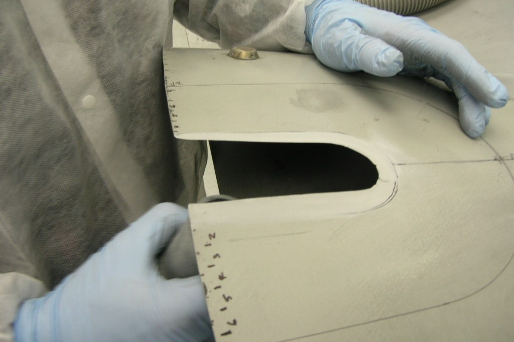
Figure 1. Remove damaged skins and core in affected area. Photo Credit, all images: Kirt Butler/Abaris Training Resources
It is always a challenge to perform through-damage repairs to a compound-contoured composite sandwich structure, especially when there is a critical aerodynamic (AD) surface to consider. It is most problematic when access is limited to one side — the aerodynamic side — where the damage removal and scarfing protocol for repair of the outer AD skin, core and inner skin would remove a significant amount of the original structure around the damage area, resulting in a greater amount of AD surface that would need to be reclaimed.
The first factor to consider is that substantial tooling may be required to regain the AD surface. This type of tooling is either taken from the same area on another part (if available) or made through additive manufacturing (AM) methods using a digital file to generate a 3D-printed tool. A second consideration is whether to approach the repair from the outside or inside of the part. While the example repair above necessitates an outside approach due to single-side access, it is more time-consuming, costly and presents a higher risk of changing the original AD profile. To avoid these factors, we look at repairing the damage from the inside using a multistep process.


Repair from the inside
If the repair technician can access both sides of the structure, then it may be preferable to do the repair from the inside (bagside) skin, thus minimizing the amount of original AD surface that must be removed and reclaimed. This can often be done with simple composite caul tooling that can be fabricated from the actual part once the AD surface has been temporarily recovered using common epoxy filler materials and sweep/splining methodologies.
Temporarily reclaim the aerodynamic surface
The first step is to perform a damage assessment/inspection and determine the extent of the damage area to be removed. Next, before removing any structure, remove high spots, clean the surface and mask-off around the periphery with one layer of tape. Fill the damage area to at least 0.5-inch (12.7-millimeter) deep with an appropriate amount of epoxy filler paste (or other stable filler material), spline to match the AD surface (plus tape thickness) and cure the materials. Remove the tape, and carefully scrape or sand back to the original surface profile.
Fabricate a semi-rigid caul tool
Map out the estimated area that will need to be controlled with a semi-rigid caul tool. This includes supporting inside and outside skin repair areas. Provide temporary index features on the part, just inside of the outer boundaries of the tool coverage area, so that the tool can be precisely located back to the part. Temporarily extend any edge band areas if applicable. Cover the part area with an adhesive-backed layer of polytetrafluoroethylene (PTFE)-coated fabric1, cutting out around the index locations as needed. Treat the index features with a coat of carnauba wax or other release agents. Mask-off and cover outside of the tool periphery as needed to keep the rest of the structure clean during layup and processing of the caul tool. Fabricate a 0.1-0.2-inch (2.5-5.1-millimeter) thick composite caul tool using low-temperature cure/high-temperature service wet layup (or prepreg if applicable) materials per standard shop practices. Carefully demold the caul tool without disturbing the index features. Remove the PTFE-coated fabric and thoroughly clean the tool and part surfaces with clean wipes and solvent. Apply a layer of PTFE-coated fabric on the surface of the caul tool to bring the surface back to the AD profile — do not cover the indexes. Cure the caul tool laminate above the glass transition temperature (Tg) of the repair materials to prevent distortion during the repair sequences.
Remove damaged area and prepare for repairs
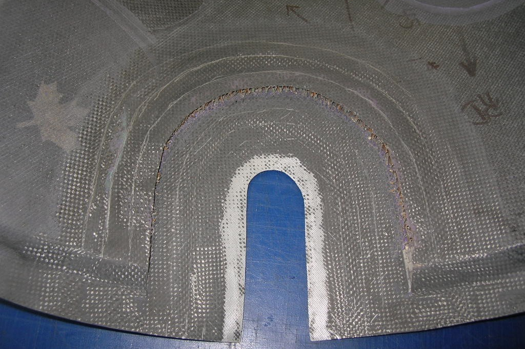
Figure 2. The inner skin and core are machined away in the local repair area for the outer skin. This is followed by taper scarf machining of the inside surfaces of the inner and outer skins that will be repaired.
Route or grind out the damage area through the entire structure as shown in Fig. 1. Cut out the damaged core and inner skin to approximately 0.8 inch (20 millimeter) beyond the edge of the total scarf distance. The scarf distance is based upon the number of plies in the outer skin multiplied by 0.5 inch (12.7 millimeter) per ply from the edge of the damage removal. This enables inner skin repair plus an extra landing for the core replacement. Proceed to machine the taper scarf for the outer skin and inner skin repairs as shown in Fig. 2.
Repair the outer skin from the inside
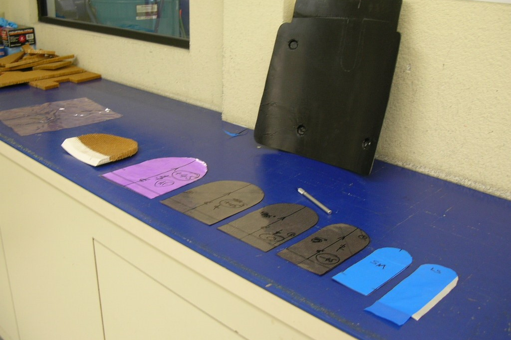
Figure 3. All adhesive layers and repair plies are precut to size and the caul tool is prepared for installation.
Clean all inside and outside surfaces, then install the semi-rigid caul tool and secure to part with flash tape. (The vacuum bag will later provide clamping pressure.) Prepare repair plies and adhesives for outer skin repair (Fig. 3). Fabricate a core replacement plug, potted along the tapered edge and set it aside for later. Layup, bag and cure the outer skin repair per standard practices (Fig. 4). (Note: This repair was cured using insulation behind a heat blanket under the bag, against the semi-rigid caul. Thermocouples were placed between the heat blanket and the semi-rigid caul and inside, on top of a thin (0.06-inch, 1.5-millimeter) aluminum caul plate, to monitor temperature of the blanket and control repair temperature.) Remove bag materials, etc. and lightly abrade and clean surface prior to the core replacement.
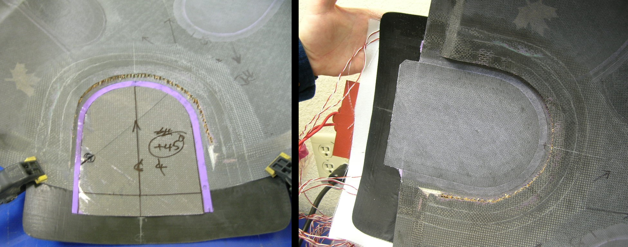
Figure 4. The repair patch for the outer skin is laid up (left) and fully cured (right), prior to replacing the core plug.
Install core replacement plug
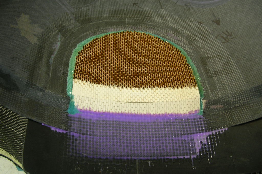
Figure 5. The potted core replacement plug is bonded in place with a layer of adhesive under the core and foaming adhesive around the periphery. It was then cured and is ready for final machining/profiling.
Lay up an adhesive layer over the repair and on the landing, up to the edges of the surrounding core. Install a core splice adhesive around the outer edges of the core plug and install in the cavity. Apply peel ply and other bagging materials as needed and draw partial vacuum, ~15 inches Hg. Cure as required. Afterward, the core is machined to the desired profile and all dust and debris are cleaned from the area prior to performing the inside skin repair. Reference Fig. 5 for the cured core plug. (Note: A hot air machine2 with a localized oven tent made from water heater insulation was used for curing the core bond and the subsequent inside skin repair. Temperature was controlled with a hot bonder and thermocouples located around and inside the core.)
Final repair to the inside skin
The inside skin is repaired in the same fashion as the outer skin — with applicable materials — in accordance with standard methods and practices. After it has been cured, the bagging materials are extracted, and the caul tool is removed from the AD surface (Fig. 6). The temporary indexes are later removed, and the repairs are inspected using nondestructive techniques (typically tap or ultrasonic testing). At this point, the edges can be trimmed back to the original trim line.
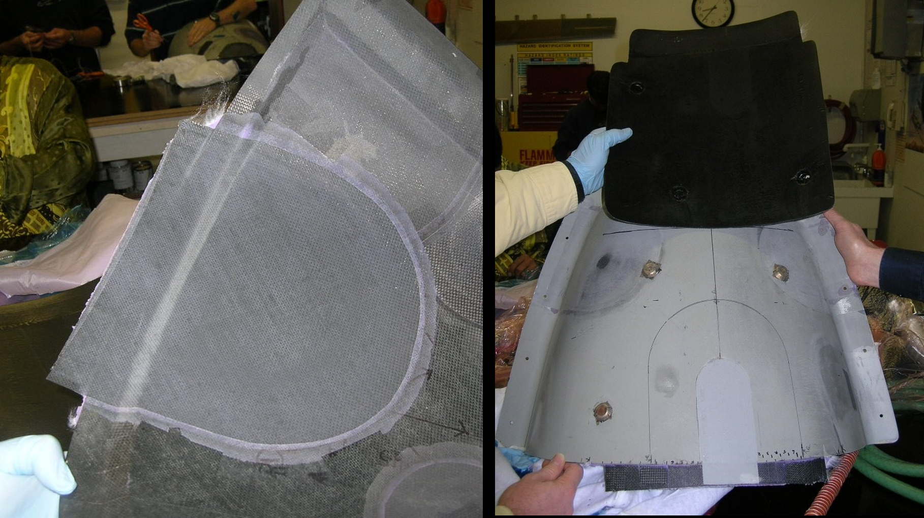
Figure 6. These photos show the completed repair of the inner skin (left) and the outer AD surface (right), which has been preserved using the inside repair approach. For reference, the black Sharpie line shows how much original AD skin was sustained.
The above examples are unique to the part that we used for demonstrative purposes in this column. Although the exact details may change, the basic concept remains the same. Ultimately, by performing the repairs from the inside there is minimal impact to the original AD surface, with no compromise to the structural repair. Always check to see if the repair scheme (size and proximity) is within the boundaries of the Structural Repair Manual or other applicable instructions. Otherwise, an engineering disposition may be required.
References:
- Tooltec A500 PTFE-coated glass fabric, adhesive backed from Airtech International (Huntington Beach, Calif., U.S.).
- HCS2041-02 hot air curing system from Heatcon (Seattle, Wash, U.S.).


.jpg;maxWidth=300;quality=90;format=webp)


Related Content

Developing repairs for thermoplastic composite aerostructures
HyPatchRepair project proves feasibility of automated process chain for welded thermoplastic composite patch repairs.
Read More
Segula Technologies initiates Z-WasTEK project for composite recycling, repair
The combined use of 3R resin and the development of digital programs will target the repair and more responsible use of carbon fiber.
Read More
Toray jointly wins Infrastructure Maintenance award for steel pipe repair innovation
Together with Tokyo Electric Power Grid and Yasuda Seisakusho, Toray employed in-situ VARTM with carbon fiber sheets to repair steel pipe corrosion on transmission towers, with application extension underway.
Read More
INFINITE consortium tackles wireless sensor integration for life-long aircraft monitoring
Engineers from University of Sheffield AMRC will support the embedding of highly specific sensors into composite aerospace structures for MHM and SHM and recylability opportunities.
Read MoreRead Next

A second look at cobonded tapered scarf repairs for composite structures
Composites repairs, such as cobonded tapered scarf repairs, seek to sufficiently restore structural loads so that components perform without failure
Read More
The basics of composite drawing interpretation
Knowing the fundamentals for reading drawings — including master ply tables, ply definition diagrams and more — lays a foundation for proper composite design evaluation.
Read More
Alternate heat sources for hot-bonded composite repairs
Successfully using an alternate heat source for repairing composite structures requires an awareness of thermal dynamics and effective heat transfer management.
Read More