


Source | APWORKS
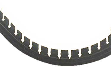
Hyperjoint is a patented technology that creates a stronger, tougher, more robust joint compared to traditional bolted and adhesively bonded joints. The concept uses arrowhead-shaped pins 3D printed as an integral part of additive manufacturing metal components. These are made using laser beam powder bed fusion, better known as selective laser melting (SLM).
The pins, printed in titanium to avoid galvanic corrosion with carbon fiber, are pushed through ≈75% of a composite laminate’s plies and then the assembly is vacuum-bagged and cured. The result is a hybrid structure — half composite, half metal — which can handle higher loads than current bonded and bolted joints but without drilling holes or using redundant “chicken rivets” (see “certification of bonded composite primary structures”).


Currently, bonded composite primary structures require a redundant load path in case of failure. Hyperjoint provides not only a higher lap shear strength versus bonded joints, but also a geometrical locking of the pins in the laminate. Source | APWORKS
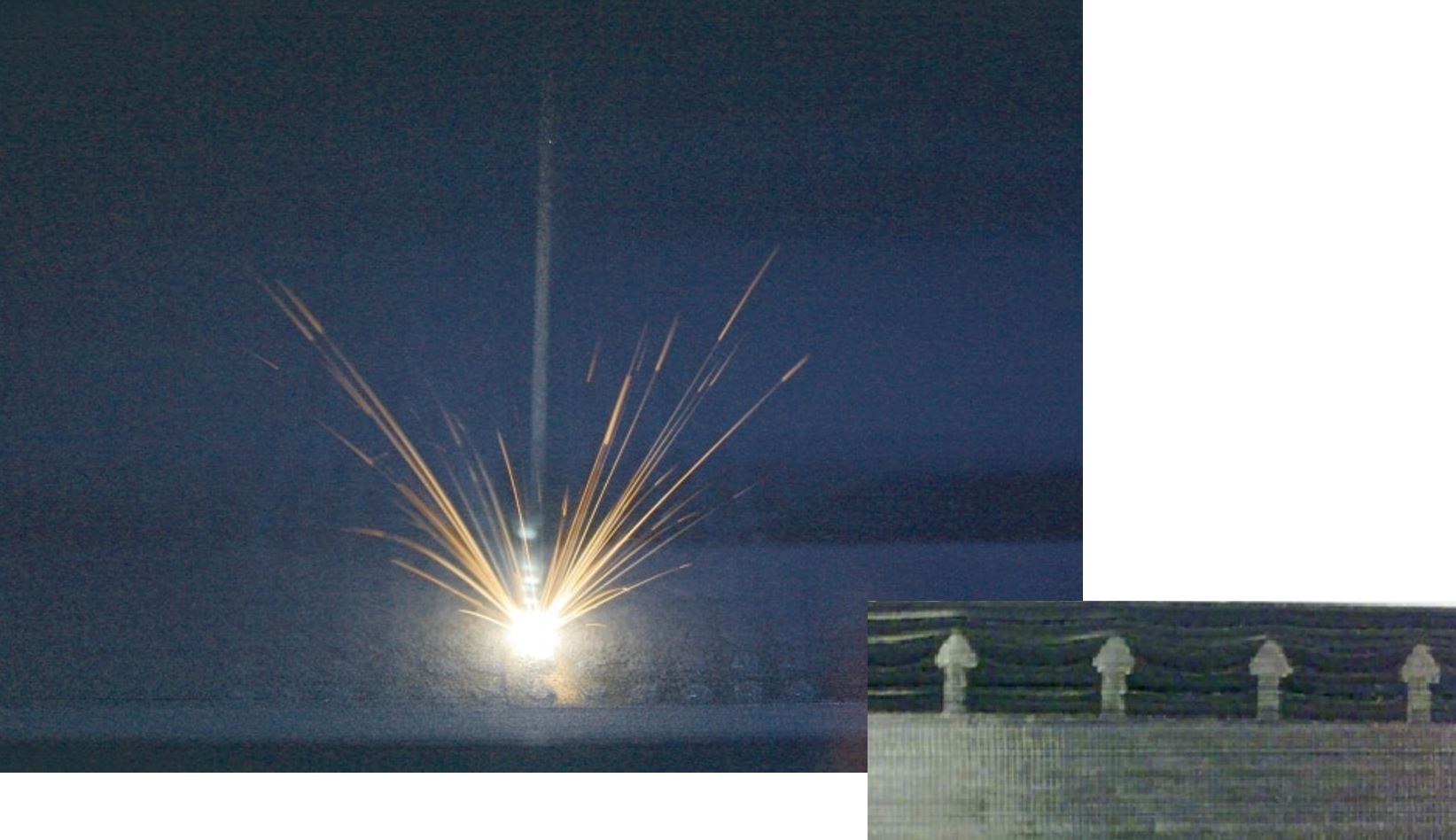
Hyperjoint pins, created as an integral part of the metal component made using selective laser melting (SLM), feature a conical arrowhead shape that prevents pull-out. Source | “Additive assembly: the 3D printed fastener” by Jon Excell, The Engineer magazine and Fig. 2.14, “Numerical modelling of through-thickness reinforced structural joints” by Francesco Bianchi, Cranfield University.
The technology was developed by Airbus Innovation Works in the U.K. (Filton) more than a decade ago and advanced as a means of achieving rivetless assembly. “Though we were proceeding with Hyperjoint within Airbus,” explains one of the technology’s key developers, Jonathan Meyer, “the process for application to commercial aircraft is very long and linear, moving in incremental steps.” Meyer saw a way to potentially speed and broaden applications.
In 2013, Airbus Innovation Works in Germany had spun off APWORKS (Taufkirchen, Germany) to commercialize metal additive manufacturing technologies like Scalmalloy — an aluminum-magnesium-scandium alloy offering benefits over aluminum powder for SLM. “APWorks had so much success with Scalmalloy,” says Meyer, “we wanted to do the same with Hyperjoint.” Thus, after a decade at Innovation Works and becoming the company’s technology roadmap owner for additive manufacturing processes, Meyer joined APWORKS as chief product officer in 2019. That same year, APWORKS was acquired by Tier 1 supplier Premium AEROTEC Group (PAG, Augsburg, Germany). “Our focus now is to work with composites companies to develop applications where bolting and bonding are not sufficient and/or too expensive,” notes Meyer.
Additive assembly demonstrator
In 2014, Meyer and fellow Airbus Innovations engineer Philip Parkes, now head of virtual product engineering at APWORKS, demonstrated Hyperjoint with Charge Bikes (Somerset, U.K.). They printed each of the two seat rails as a Hyperjoint component with integral pins on the ends. These were inserted into the seat’s carbon fiber-reinforced polymer (CFRP) laminate and cured. As explained in the July 2014 article, “Additive assembly: the 3D printed fastener” by Jon Excell in The Engineer magazine:
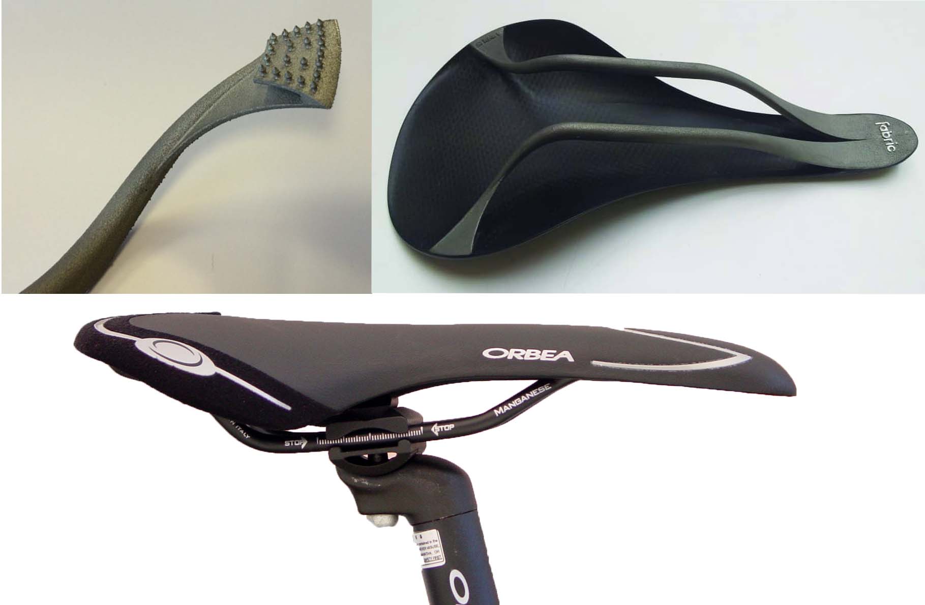
For the Charge Bikes demonstrator, two seat rails were printed with pins on each end (top left). These were inserted into the carbon fiber seat laminate (top right shows bottom of seat with rails attached) and cured. The image at bottom shows an example (not from Charge Bikes) of a more conventional seat with rail beneath attached to the bike’s seat post. Source | Wikimedia Commons (bottom) and “Additive assembly: the 3D printed fastener” by Jon Excell, The Engineer magazine (top).
“Traditionally, saddle makers use glue or bolts to attach rails to a saddle’s base. ‘The Charge project was a useful learning exercise,’ says Philip Parkes … The pins we used were much smaller at around 1-2 millimeters tall. The laminate was thinner and curved than configurations we had previously tested … ‘We have a lot of options to play with,’ says Parkes. ‘For instance, the pin has a conical head feature that prevents pull-out. We are testing how the size of that, compared with the shaft below, affects its strength. We’re also looking at the angle when inserting them into the composite, as well as how the spacing between the pins affects performance.’
Meyer notes that laminates used in Hyperjoint structures now are typically 3 to 7 millimeters thick, while pins range from 2.4 millimeters for thinner laminates to 3.6 millimeters for thicker laminates. While still at Airbus, Meyer and Parkes did test different pin shapes, shaft diameters, spacing, depth of pins in the laminate and many other parameters. They also obtained numerous patents. “We have a lot of levers we can pull to tune a Hyperjoint’s failure mode,” says Meyer. “But we’ve also developed some standard configurations that perform well to replace typical bonded and bolted joints.”
Stronger, tougher, more robust joints
In general, Hyperjoint shear strength is 50-55 megapascals.
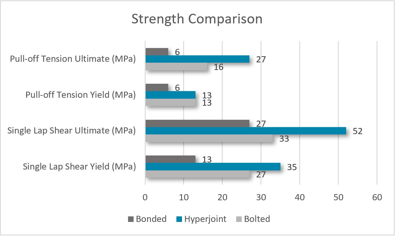
Test results for equivalent bonded, Hyperjoint and bolted joints in composites. Source | APWORKS
“In unbalanced lap shear tests with a large peel component resulting at the toe of the joint, the Hyperjoint reached about 6.5 times the strength of the equivalent bonded joint,” says Meyer. “In pure shear loading — the best case for the bonded joint — Hyperjoint gives more like double the strength, but so much depends on the setup you benchmark against.”

Hyperjoint increases joint toughness and damage tolerance versus equivalent bonded joints.
Source | APWORKS.
Even so, the toughness and robustness possible with Hyperjoint can be seen in the graph of lap-shear test results at right. The adhesively bonded joint for comparison is shown at bottom left in red. The next curve, represented by a solid black line, is an equivalent Hyperjoint where the pins were painted with PTFE to simulate no bonding with the composite laminate resin. The highest curves, shown with dashed purple lines, are the equivalent Hyperjoint which has bonded during the normal composite molding process. “So, Hyperjoint offers higher damage tolerance,” says Meyer. “Higher energy is required to fail this joint — 16.7 joules compared to 0.2 joules for the bonded joint. There is also a 400 percent increase in elongation at maximum load. And even when we got rid of adhesion to the laminate completely, the ultimate strength was still much higher than the bonded joint,” Meyer points out.
Hyperjoint also exceeds the performance of equivalent bolted joints. This can be seen in the graph below, which shows the static design envelope of the Hyperjoint versus equivalent bolted joints, based on more than 100 Arcan tests (see sidebar "Arcan test” below).
“We chose the Arcan test because it enables us to understand the behavior of the joint under different loading angles,” Meyer explains. “Due to the fact that composites are highly anisotropic, we need to understand how the joint will behave when loads are introduced at different angles.”
In the graph:
- Horizontal (x) axis is the shear component of the load (Fx, loading in the plane of the laminate)
- Vertical (y) axis is the tensile (out of plane) component of the load (Fz)
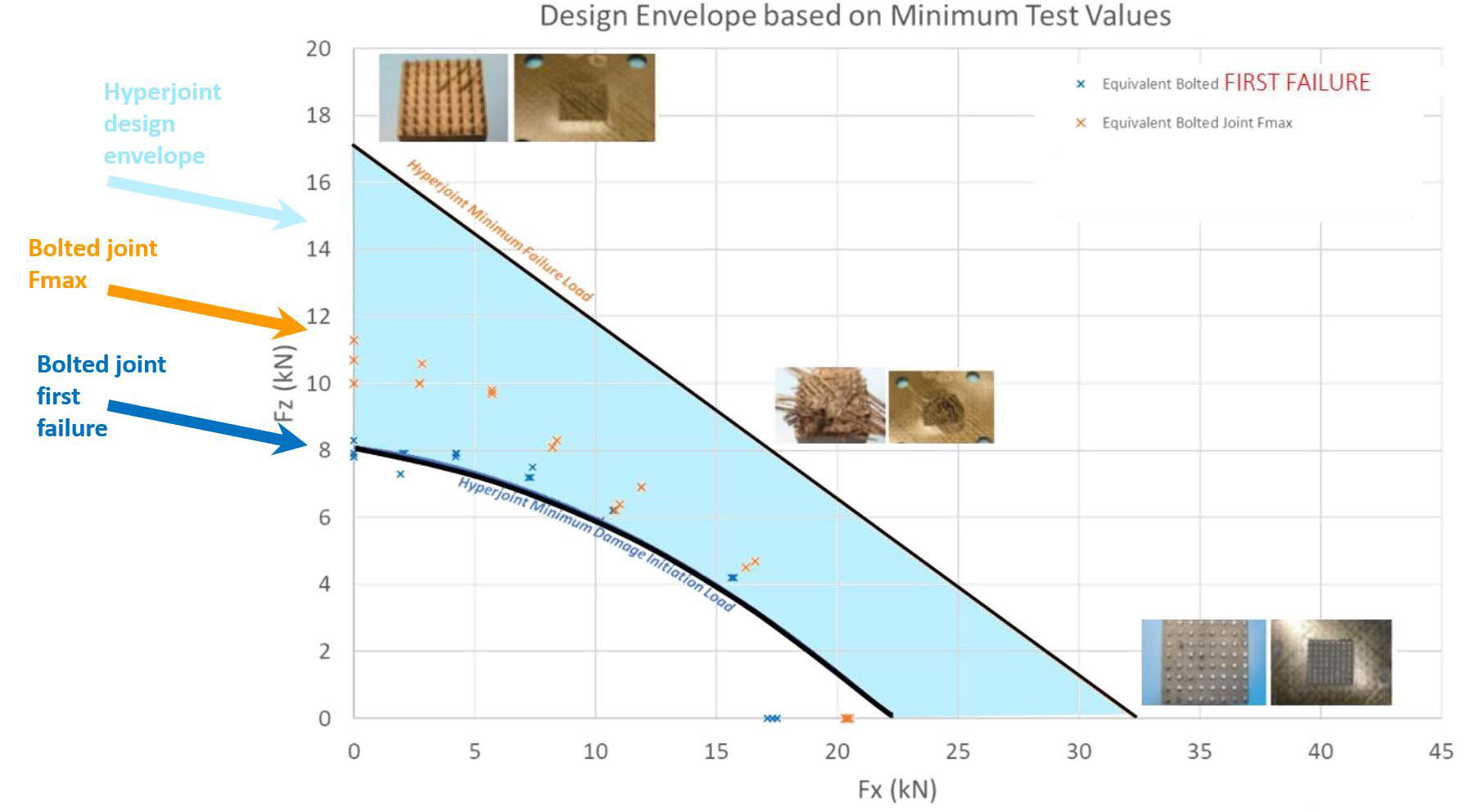
Static design envelope of Hyperjoint exceeds that of equivalent bolted joints. Source | APWORKS
“We tested across a range of angles between 0 and 90 degrees,” says Meyer. “All tests were performed on a single type of pin array geometry in a vacuum-bag cured prepreg CFRP laminate. The black lines on the graph show the envelope representing the absolute minimum failure values for Hyperjoint specimens with a patch area of 25 millimeters by 25 millimeters. The orange and dark blue datapoints show equivalent results for a bolted joint. Therefore, we compare conservative worst-case Hyperjoint results with ‘typical’ bolted joint test points.”
Tuning failure modes
The photos shown in the graph above represent Hyperjoint failure modes at 0, 45 and 90 degrees (click graph to enlarge). “You can see that in pure tension (top left) at 90 degrees, the Hyperjoint pins pull out of the laminate,” says Meyer. “The failure mode is pull-off. The pins are grabbing several plies of the laminate, so you don’t get first ply failure as you would in a bonded joint and compared to a bolted joint you also have much higher residual strength.” Why? “Because the total perimeter area of the ‘plug’ of composite under the Hyperjoint pins in a typical array is much larger than that of the equivalent bolt head, and that is where the work is done in a pull-through failure,” he explains.
“In pure shear (bottom right) at 0 degrees,” Meyer continues, “the pins are cleanly sheared off, while at 45 degrees they tear the laminate fibers out. So, this combination of shear and tension is where you have big peel forces, and that’s also where Hyperjoint comes into its own because the pins act like little anchors that can react to the bending forces in the composite laminate.”
“We’re in the same region as a bolted joint,” Meyer continues, “but we eliminate the knockdown, time and expense of drilling holes. We can also tune the joint failure modes by changing the pin geometry and the spacing in the array, so this design envelope is just one example.”
Arcan test
The diagram below shows the Arcan test rig and specimen geometry. The square plate is CFRP and the tall block with the hole & slot is titanium. They are connected with a Hyperjoint.

Arcan test equipment and set up. Source | APWORKS
In the test, the assembly is subjected to loading at a certain angle. The test machine starts at a displacement of zero and gradually increases the displacement over time at a constant rate (millimeters/minute). The load is measured through the load cell showing how much force is required to achieve the displacement.
F1 (First Failure) is defined as any indication of damage or permanent deformation. An initial damage will result in a temporary reduction in the measured force at a given displacement. As the displacement increases, the force again increases until eventually, the part breaks and the load drops to zero. Fmax (maximum force) is defined as the highest load the joint transfers at any point in this process.
Composites processes
The basic process to use a Hyperjoint is to proceed with composite layup as normal. The Hyperjoint fitting is then integrated prior to vacuum bagging. “Required insertion forces are low,” says Meyer, “so the typical low-tech solution is to tap the part in using a mallet. Caul tooling is required to avoid wrinkles at hard edges and to plug features in the part geometry in order to avoid resin pooling.” Hard tooling can be used for more precise relative positioning and also achieve insertion once vacuum pressure is applied.

Hyperjoint integration process. Source | APWORKS
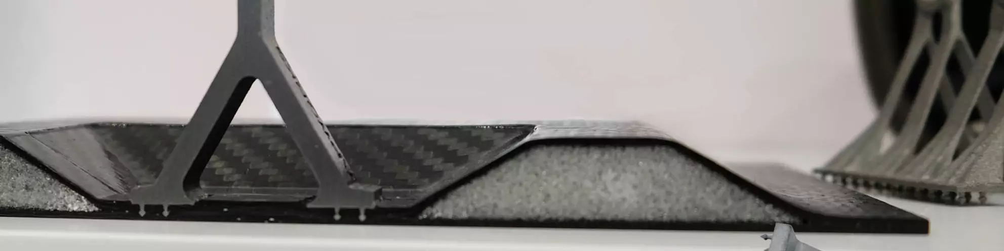
This cross-section shows how, in a curved joint, Hyperjoint pins are pushed into the composite laminate on a common axis, resulting in some pins inserted at an angle, while others extend further into the laminate than others. This is accounted for in the joint design. Source | APWORKS
Though using Hyperjoint with curved surfaces and corner fittings is possible, it is a bit trickier. “Insertion of the pins must be done based on a common axis,” Meyer explains. “This means that even though the laminate might be curved, the pins all need to be parallel to one another so that you can push them in, as they are printed on the fitting.” Thus, some pins are penetrating the plies at an angle, rather than perpendicularly.
“We have devised ways for corner fittings, but the easiest solution is to preform the laminate in a mold and then insert the pins on a common axis, as with a curved laminate,” he notes. “It’s mostly a matter of developing appropriate caul tooling.”
Hyperjoint is easy to use with prepreg, says Meyer, but is a bit trickier with resin infusion and resin transfer molding (RTM). “With resin infusion processes, the resin is less viscous and so resin rich areas form around the pins. This doesn’t really affect the joint performance in shear, but can influence the tension (pull-off, out of plane) strength of the joint, where matrix properties play a role. However, in the limited tests we’ve done with liquid resin infusion (LRI) processes, the pull off strength was still in the same ballpark as for prepreg, just with more scatter in results.”
What about fiber damage from insertion into the reinforcements? “There isn’t fiber damage from insertion, but fibers are deviated around the pins,” Meyer responds. “The impact with prepreg is minimal, as the resin systems are very viscous and under bag pressure they draw the fibers back under the head of the pins to give the illusion that getting them in there must have been a magic trick. Of course, the individual fibers do follow a shallow ‘eye shaped’ curve around the neck of the pin and so there is some knock-down to the in-plane properties compared to a laminate with no pins. Our testing shows that knockdown is much less than for a bolted joint.”
Although the majority of testing has been completed using laminates made with unidirectional carbon fiber/epoxy prepreg tapes and automated fiber placement/tape laying (AFP/ATL), Meyer notes good results with woven prepreg and a demonstration project with polyetheretherketone (PEEK) thermoplastic prepreg in a driveshaft application.
Commercial targets
Hyperjoint is continuing its development for aerostructures, but one of the key reasons it is being commercialized by APWORKS is to broaden its application. “We see a good fit with low-volume, high-performance applications,” says Meyer. Hyperjoint also works in laminates using glass fiber. “It might also provide a solution when dealing with aramid fibers such as KEVLAR and UHDPE (ultra high-density polyethylene) fibers such as Dyneema and Spectra, where bonding is notoriously difficult and a mechanical joint of this type might be very advantageous.”
“APWorks is very innovative and disruptive with regard to metals additive manufacturing,” Meyer observes. “We’re looking for like-minded composites manufacturers to partner with and further develop this technology.”


Related Content

CW finalizes Tech Days: Bonding and Welding agenda
A total of six presentations — four welding and two bonding — presented by industry experts will explore the drawbacks, potential and evolving technologies available to bonding and welding methods.
Read More
Click Bond unites bonding science, fastening innovation with Brighton Science acquisition
Click Bond expands its ability to deliver measurable, scientific confidence from surface to structure.
Read More
AnalySwift receives NASA STTR contract to enable second-use spacecraft infrastructure
Together with Purdue, AnalySwift aims to develop a composite heater layer and a novel software tool or module to achieve assembly, disassembly of thermoplastic composite joints in space during long-duration missions.
Read More
Plasma moves beyond improved bonding to coatings, multifunctional composites
Plasmatreat cold plasma systems clean, activate surfaces and apply nanocoatings for dielectric barriers and more.
Read MoreRead Next

Thermoplastic composite materials and processing interactions
Selection of product material formats and their interactions with various process methods heavily influence a final TPC part’s properties and fabrication options.
Read More
From PMCs to sandwich composites: Tracing the path of test method standardization
Over the decades, progression of PMC and sandwich composite test method development and standardization has been shaped by the requirements of the composites industry.
Read More
Robotic computed laminography brings X-ray CT resolution to large composite structures
Omni NDE collaborative robots, X-ray end effectors and Voxray’s reconstruction approach enables 5-micron inspection of aerospace parts without size constraints.
Read More