


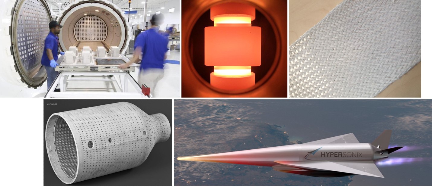
CMC scales for growing, faster, hotter applications. GE Aerospace has pushed CMC production to new levels (top left) to meet aviation’s need for faster, more efficient engines. Other growing markets include space, for parts like rocket nozzles (lower left), and hypersonic vehicles, like those being commercialized by Hypersonix (lower right). To meet this demand, faster processing is maturing, such as MATECH’s FAST sintering (top center) used to densify C/SiC and SiC/SiC CMC in <10 minutes. CMC fiber is also being produced in Europe, such as DITF’s OxCeFi fibers (top right), successfully braided and tested in OCMC parts and being commercialized to industrial scale by Saint-Gobain. Photo Credit (top left, clockwise): GE Aerospace, MATECH, DITF, Hypersonix and ©DLR-WF via the Ceramic Network
Landscape photo, top: Filament wound CMC parts produced by Schunk Kohlenstofftechnik (Heuchelheim, Germany). Photo Credit: Schunk, Ceramic Composites network/Composites United
Ceramic matrix composites (CMC) use ceramic fibers in a ceramic matrix to enable high-performance structures at high temperatures. For example, the silicon carbide (SiC) fiber-reinforced SiC matrix (SiC/SiC) CMC that GE Aerospace (previously GE Aviation, Evendale, Ohio, U.S.) produces for LEAP engine turbine shrouds can withstand 1,300°C, providing much higher resistance than metal superalloys like Inconel, but at one-third the density. This unique combination of properties has helped the LEAP engine run hotter with less cooling, improving efficiency to burn 15-20% less fuel, with lower emissions and maintenance. The GE9X engine, with five CMC parts, will reportedly be the most fuel-efficient engine ever built for a commercial aircraft when the Boeing 777X enters service in 2025.
Meanwhile, supersonic (Mach 1-5), hypersonic (Mach 5-10) and high-hypersonic (Mach 10-25) vehicles are in development that may need CMC not just in the engines but also in the airframes. For example, due to air friction from traveling at Mach 5, the nose cone and leading edges of such vehicles can see temperatures up to 1,600-2,800°C. R&D into ultra-high temperature CMC (UHTCMC) is aiming for service temperatures as high as 3,500°C.


CMC is also increasingly being sought for use in nuclear energy and other power generation plants (e.g., gas turbine, solar, hydrogen) as well as for thermal processes in industry. Again, higher temperatures increase efficiency. For example, prototype CMC reaction vessels for steam cracking hydrocarbons have shown as much as 50-60% improvement. However, there has been a limited supply of aluminum oxide (Al2O3) fibers used to reinforce the oxide matrix in such OCMC applications, says Denny Schüppel, managing director for the Ceramic Composites network. “High-performance OCMC use almost exclusively Nextel 610 and 720 fibers from 3M [Minneapolis, Minn., U.S.]. Other suppliers have left the market, and Nitivy [Tokyo, Japan] fibers with 85%+ oxide content are still in development.”
But now, oxide fiber production is preparing to double, says Schüppel. Founded in 2008, and now part of the global association Composites United e.V. (CU, Berlin, Germany), Ceramic Composites has helped its members bring new CMC fibers to serial production. These include oxide fibers from RATH Group (Mönchengladbach, Germany) working with Fraunhofer ISC-HTL (Bayreuth, Germany) and also Saint-Gobain Advanced Ceramic Composites (Pierre-lès-Nemours, France) in collaboration with DITF (Denkendorf, Germany). Both groups are aiming to start continuous fiber production by 2024-25. BJS Ceramics (Gersthofen, Germany) started producing continuous SiC fibers in a pilot plant in February 2021, and has received investment from aircraft engine and components manufacturer ITP Aero (Bibao, Spain).
Another challenge is lengthy production times because CMC fibers and parts typically require multiple, high-temperature thermal cycles and process steps. However, global R&D is advancing new manufacturing technologies and also targeting sustainability. This article will explore some of these developments as well as CMC’s evolving applications and supply chain.
Industrial production in Germany
Though Germany has had significant CMC research for decades, the Ceramic Composites network aims to accelerate widespread implementation of new CMC technologies. It works to disseminate information, connect industry players for technology transfer and assist companies with government support and funding. “CU and Ceramic Composites have worked with our members to receive increased EU and German funding for a wide range of projects,” says Schüppel. The network published a CMC global market report in March 2023. This valuable resource — an abridged version is free — details commercially available fibers and producers, types of CMC, their processes and applications, as well as new developments from Ceramic Composites members. Parts of the infographic below were developed from this report, along with a position paper published in 2021.
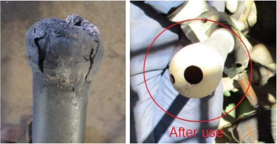
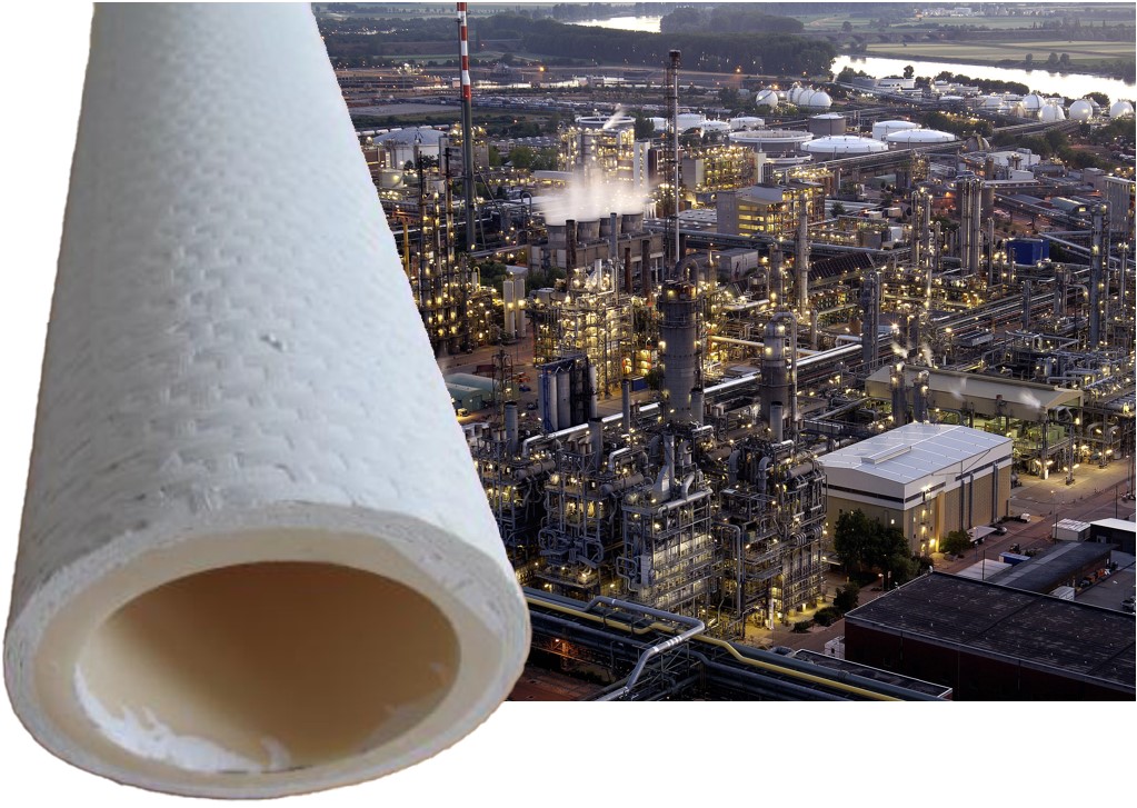
Figure 1. CMC parts boost efficiency, enable energy transition. Burner lances made from Keramikblech oxide fiber/oxide matrix (OCMC) offer 10 times longer life versus metal alloy burner lances used in steam crackers (top). A hybrid OCMC furnace tube (alumina liner, metal insert, outer OCMC sheath) has successfully demonstrated electrical-powered steam cracking (bottom left). BASF Ludwigshafen has installed the world’s first large-scale electrically heated steam cracker plant, with a potential 90% reduction in CO2 emissions (bottom right). Photo Credit: Walter E. C. Pritzkow Spezialkeramik
Member Walter E.C. Pritzkow Spezialkeramik is a five-employee company near Stuttgart founded in 1994 by Walter Pritzkow after working with CMC at the German Aerospace Center (DLR). The company’s award-winning Keramikblech OCMC uses fabrics of Nextel 610 and 720 fibers and a hand layup process to create a wide array of parts. “We work mainly with industrial companies,” says Pritzkow, “such as Linde and BASF, but also with companies doing metal casting and heat treatment. We do small series of 10-100 parts but also larger production of parts like burner systems where we deliver 2,000 to 5,000 parts per year.”
Keramikblech currently uses mostly woven fabrics but also braided sleeves. The latter can be supplied affordably by a specialty braider in Germany in lengths up to 200 meters. Pritzkow explains the CMC production process: “We infiltrate the fabric with a water-based ceramic slurry using a doctor blade [squeegee] and then apply the wet fabric onto a special plastic mold. This is dried in a normal drying furnace at 60-90°C (for 4-5 hours up to 20 hours, depending on part thickness, size and complexity). We then remove the green body from the plastic mold and sinter it (1,100-1,200°C), typically overnight, in a standard sintering furnace. We machine the parts with diamond tools, and hole patterns in plates are laser cut.” Parts can be made and shipped in as little as 3 days.
But what about quality, and why not use SiC? “Because SiC/SiC and C/SiC are much more complex materials and require longer processing. My parts are easy to fabricate. Even though we don’t use an autoclave, like CHI [Composites Horizons Inc.] and COIC [COI Ceramics], I’ve compared our bending strength to theirs and found no difference. We use a matrix with alumina and zirconia (ZrO2) as a binder, which produces good preforms and CMC with good high-temperature properties. Our parts are typically used at 1,150-1,200°C; the maximum would be 1,280°C.”
The company also works with R&D centers and completes development projects for customers. “We are located near DITF and tested their oxide fibers in unidirectional and woven fabrics in a project with BASF,” explains Pritzkow. “The fibers they have developed are at the same level as Nextel fibers.” He is optimistic about Saint-Gobain’s industrial production of the fibers. “Nextel fabric is the most expensive part of our products,” he notes, “and delivery is a problem, often with delays of 3-6 months.”
Pritzkow sees a large potential for OCMC parts in the future. “More and more applications are being developed,” he says. “In the beginning, we worked with specialty companies and niche applications, but now large companies want to run thermal processes at higher temperatures. We have also worked with engine manufacturers and now have a project with Atmos Space Cargo [Rheinmünster, Germany] to develop a high-temperature fan using OCMC.”
Still, industrial applications will move much more quickly, says Pritzkow, “especially if oxide fiber costs come down. We’ll get more opportunities to replace metal parts which are destroyed in weeks and months due to coking and corrosion. OCMC parts provide a much higher lifetime — for example, our flame tubes last up to 4 years. Some say that our parts are too expensive, but companies like BASF have found the reduction in maintenance, shutdown and part replacement costs they provide are significant. Time without production is even more expensive. And now these companies can run for longer and at higher temperatures, so their overall efficiency is really benefiting.”
Growing use in aeroengines
CMC was originally developed for rocket nozzles used in missiles and space launch vehicles in the 1970s. It expanded into thermal protection systems (TPS) for reentry vehicles and discs/rotors for aircraft brakes by the 1980s. Safran (Paris, France) claims it became the world leader in that technology and the first, in 1996, to qualify a CMC part for aeroengines. Its C/SiC outer flaps for the French Rafale fighter jet’s M88-2 engine were baselined for serial production, and more than 15,000 have been produced and used successfully. Safran continued developing CMC components (see “Ceramic matrix composite behavior enhancement for gas turbines hot section”) including its reported first test of a CMC turbine rotor in 2010.
GE is Safran’s partner in CFM International (Cincinnati, Ohio, U.S.) which produces the LEAP engine. GE began developing SiC/SiC engine parts in the 1980s. In 2014, it opened its CMC parts factory in Asheville, N.C., U.S., followed by its continuous fiber and prepreg plants in Huntsville, Ala., U.S. in 2018 (see “Vertically integrated CMC supply chain” and “Plant tour: GE Aviation, Asheville, NC, US”). GE’s fiber is based on the industry standard Hi-Nicalon-S SiC fiber produced since 1980 by Nippon Carbon (Tokyo, Japan). The technology was transferred via the joint venture NGS Advanced Fibers (Tokyo, Japan), formed in 2012 between Nippon Carbon (50%), GE Aerospace (25%) and Safran (25%). In 2021, GE Aerospace reported annual production of up to 10,000 and 20,000 kilograms of SiC fiber and prepreg, respectively, and had built more than 100,000 SiC/SiC high-pressure turbine stage 1 (HPT1) shrouds — 18 for each CFM LEAP engine — which had amassed more than 10 million hours in service. For the GE9X, it produces HPT1 shrouds and nozzles, HPT2 nozzles and the combustor inner liner and outer liner.
Also in 2021, GE Aerospace and Safran launched the Revolutionary Innovation for Sustainable Engines (RISE) program, which seeks a further 20% reduction in fuel consumption and emissions, centered on the team’s open fan design named for its absence of a case around the GE9X-sized turbo fan. Behind the fan is the core which holds the compressor, combustor and turbine, but as developed in RISE, it will be ultracompact — smaller than on a business jet, according to Mohamed Ali, VP of engineering for GE Aviation. In a June 2023 flightglobal.com article, Ali noted that HPT airfoils for the engine have benefited from CFM’s capabilities in CMC and were already manufactured and in testing using a modified military engine. RISE is on track for ground and flight tests by 2025 and flight tests using a hydrogen engine before 2030.
According to a GE blog in June 2023, some work for the ultracompact core has been completed through NASA’s Hybrid Thermally Efficient Core (HyTEC) project, which also began in 2021. Specific goals of that program include development of CMC liners for combustors, turbine blades and vanes as well as environmental barrier coatings (EBC). Meanwhile, GE’s XA100 Adaptive Cycle Engine developed for the F-35 fighter jet uses CMC more extensively than any commercial or military aeroengine to date, according to David Tweedie, general manager for advanced product at GE Edison Works. The engine reportedly delivers 25% better fuel efficiency, 10% better thrust and significantly more thermal capability compared to the current F135 turbofan from Pratt & Whitney (East Hartford, Conn., U.S.). GE began this development in 2007 with the Adaptive Versatile Engine Technology (ADVENT) program, where its prototype set a world record for the highest combined compressor and turbine temperatures, thanks in part to CMC. ADVENT also successfully tested SiC/SiC low-pressure turbine blades in an F414 turbofan demonstrator engine in 2015.
Hypersonix
Development of CMC and UHTCMC has expanded significantly as the U.S. Department of Defense (DOD) seeks to counter threats from hypersonic weapons. Hypersonic speeds are not only reached by current long-range ballistic missiles, but also by reentry and space launch vehicles, like the SpaceX Falcon. The rapidly expanding New Space market is thus also driving new hypersonic technology.
Straddling both markets is Hypersonix Launch Systems (Brisbane, Australia) and its three hypersonic vehicles based on a patented hydrogen-fueled scramjet engine called Spartan that produces no CO2 emissions. Hypersonix states its mission is to provide reusable space launch technology that is sustainable. The company was founded in 2019 to commercialize 30 years of development by cofounder Michael Smart, whose research spans NASA Langley and the renowned Hypersonics Research Centre at the University of Queensland (Brisbane, Australia). In March 2023, Hypersonix was selected from 63 respondents to provide hypersonic vehicles for the DOD’s Hypersonic and High-Cadence Airborne Testing Capabilities (HyCAT) program, overseen by the DoD’s Silicon Valley-based Defense Innovation Unit (DIU).
The vehicle chosen by HyCAT is Dart. “It is designed to be an affordable, single-use test platform,” says Andy Mulholland, head of product for Hypersonix. “Its small size doesn’t allow for the equipment needed for recovery and reuse. But the next two vehicles are reusable: VISR, which stands for Velos intelligence surveillance reconnaissance, and the Delta-Velos Orbiter. Both will return to land on a runway. VISR is a hypersonic UAV [unmanned aerial vehicle] and Delta-Velos is our highly reusable and high-cadence solution for delivering small satellites to orbit.”
While Dart is fully 3D printed from Inconel metal alloy, VISR and Delta-Velos will need CMC to address the very high temperatures they will encounter at the faster speeds needed to access space and reenter Earth’s atmosphere, explains Sam Grieve, manufacturing lead at Hypersonix. “If we didn’t use CMC, we’d need an ablative TPS like other spacecraft.” Vaporized during reentry, ablative TPS must be re-applied, which adds complexity, weight and cost. High temperature CMC (HTCMC) is a better solution, he says, “to handle temperatures that are generated from friction with the air, but also from combustion inside the engine.” To that end, Hypersonix recently received a C/SiC demonstrator part that was designed in-house but produced, notes Smart, “using a very complex, never-done-before process working very closely over the last 2 years with a team of experts in Germany.”
Figure 2. Hypersonic HTCMC demonstrator. The Spartan scramjet engine (left) is integrated into the airframes of Hypersonix’ vehicles (above). The C/SiC combustion chamber below is not for flight, but to demonstrate the high-temperature ceramic matrix composite (HTCMC) manufacturing needed for future reusability and flight speeds up to Mach 12. Photo Credit: Hypersonix
The C/SiC part is a Spartan scramjet combustion chamber (Fig. 2) that is expected to handle temperatures up to 1,400°C. “It’s a manufacturing demonstrator that teaches us about the material and the technology,” says Grieve. “We’re hoping to eventually have these parts produced here by a local supply chain, but we may also produce some parts ourselves.” Mulholland notes it’s not a flight piece, “but is just to demonstrate that we could make the variable and intricate geometries needed. C/SiC was chosen as a more basic and well-understood HTCMC to start with, but eventually we’ll need much higher temperature materials.”
Where will these materials be used? “First for parts where combustion is occurring,” says Grieve, “and then other parts of the engine, followed by airframe leading edges that are directly exposed to hypersonic air flow.” Will Dart use a CMC combustion chamber in its Spartan engine? “Not in the engine,” says Grieve, “but we are planning for parts like leading edges. CMC technology is important for enabling reusability, but that’s not required for our first Dart vehicles. Our HTCMC demonstrator and development now is to prove out technology we’ll need as we move forward.”
The Dart’s first flight via the HyCAT program is planned for 2024 using Rocket Lab’s (Long Beach, Calif., U.S.) Hypersonic Accelerator Suborbital Test Electron (HASTE) rocket as a booster. Grieve explains why. “Spartan produces thrust as air enters through an inlet, gets compressed, then injected with fuel and combusted, which adds energy to the air flow, and then expands as it exits the nozzle. But unlike a turbojet, we have no moving parts — our compression is done by shockwaves which come off the front of the vehicle. The booster gets Spartan to the speeds above Mach 5 that it needs to operate.”
In August, Hypersonix announced an exclusive teaming agreement with Kratos Defense & Security Solutions (San Diego, Calif., U.S.). “This is complementary to our contract with DIU,” says Mulholland, “and gives us another channel for commercialization. Kratos also has a lot of experience in the space market and their Zeus rockets can also be used as a booster for Spartan.”
These first contracts are a key step in the company’s vehicle development. “As we continue to develop VISR and Delta-Velos, we’ll be running up against the limits of materials technology pretty quickly,” says Grieve. “There’s a nonlinear increase in temperature with Mach number, and our scramjet engine is designed to operate up to Mach 10, and we think even Mach 12. So, we’re going to reach pretty crazy temperatures sooner than later, and we’ll need to find and prove out new HTCMC and UHTCMC materials.”
FAST: 99% dense CMC in <10 minutes
A possible pathway for producing UHTCMC materials is spark plasma sintering (SPS), a process used to synthesize metals and ceramics by applying high amperage, pulsed direct current (DC) to powder in a sintering die (Fig. 3). Developed in the 1960s by Sumitomo Coal Mining Co., SPS was reported to achieve uniform, high densification in one-tenth to one-twentieth the time compared to conventional methods and use 60-80% less electricity. Modified to use a pulsed DC or AC power source, the process became known as field-assisted sintering technology (FAST) in the 1990s, according to FCT Systeme (Frankenblick, Germany), which claims it developed a novel process and the first FAST furnace in Europe in 2002. FAST reportedly enables the furnace to be “tuned” to the specific material being processed, which makes heating even more efficient than SPS.
Development has continued, with hundreds of SPS/FAST systems in use for R&D and commercial production. The Penn State Applied Research Laboratory claims FAST can be used to sinter CMC and metal matrix composites, achieving 100% density of near-net shapes at rates 70-80 times faster than conventional methods. In general, higher density enables higher mechanical properties.
Meanwhile, Safran announced in 2022 its investment in Sintermat (Venarey Les Laumes, France), citing its SPS technology that works with composites and biomaterials to produce complex shapes with a homogeneous microstructure. “This investment and our technology partnership will support Safran’s research and technology efforts,” said Eric Dalbiès, Safran senior executive VP of R&T and innovation,
“especially concerning the materials and production processes for the components on tomorrow’s aircraft engines, reflecting the disruptive technologies needed to support the development of a more sustainable aviation industry.”
After years of CMC and UHTCMC materials and process R&D, MATECH (Westlake Village, Calif., U.S.), founded in 1989 by Ed Pope, began looking into FAST. Pope knew it worked great with powdered metals, ceramics and ceramic metal composites (cermets) but what about with continuous fiber CMC? “There was interest from the Office of Naval Research,” he says, “which is still pushing today for 2,700°F CMC for higher efficiency turbine engines. So, I talked to industry colleagues to see what had been tried. Their results were disappointing. The main approach was to begin with a 40-50% densified CMC and then use FAST, but what they ended up with was nowhere near 100% dense, and the properties were terrible because the fiber had been destroyed. I realized this approach was trying to get too much done in one step. The preforms had to be more dense to start with, down to 7-10% porosity. But that could be done with typical polymer impregnation pyrolysis [PIP], chemical vapor infiltration [CVI], melt infiltration [MI] or other processes. You then apply FAST. We demonstrated that this works, and we can get up to 99.9% dense SiC/SiC in less than 10 minutes with the strength and toughness we expect from a CMC.”
Fig. 3. FAST SiC/SiC parts. MATECH’s patented process (top) uses standard field-assisted sintering technology (FAST) equipment (bottom) which applies pulsed electrical current and a pressing force through a die into a CMC part, so that material reactivity and temperature increases through Joule heating. Photo Credit: MATECH, Fig. 2 from FCT Systeme Booklet FAST/SPS First Edition 2022
To prove the process works and measure critical properties, MATECH started with simple geometries including round discs and rectangular plates. More complex geometries, such as the aeroengine doublet vane shown in Fig. 3, are possible using graphite tooling within the FAST die. This was already designed for use with PIP but not yet used to create a FAST-densified part. The FAST process time, pressure and temperature for a shaped part is the same as a flat plate geometry.
Pope obtained two patents for this development: a process patent in 2019 and a composition of matter patent in 2020. “We were able to show we can reach near theoretical density for C/SiC and SiC/SiC composites,” he explains. “We have done limited testing with both types of CMC parts in rotational detonation engines at Wright Patterson [Air Force Research Lab, AFRL] that performed really well, but we haven’t made hot section blades or vanes to put in a test rig yet.” MATECH’s work so far has focused on precursor CMC made using PIP, which is highly amenable to complex shapes and fiber architectures. “We’ve found that 1,800°C was the sweet spot for this type of FAST processing of SiC/SiC CMC,” says Pope, “to achieve the density and fracture behavior we want.”
MATECH’s densification of SiC/SiC and C/SiC CMC has used between 30 and 100 megapascals of pressure. “This is a typical range used in FAST processing,” says Pope. “The electrical current used ranges between 2,500 and 10,000 amps, depending on sample size. But that is concentrated in a relatively short burst, which makes it much more efficient than hot-pressing techniques. Also, the heat is generated within the material itself — you’re not heating from the outside. By using electrical current and the pressure of the die, you’re efficiently adding thermal energy, but also vibrational energy which makes the material more reactive.” He adds that FAST opens the door to performance gains for hypersonic leading edge, nose tip and propulsion applications that were previously unattainable.
Laser CVD, short SiC fibers
Founded in 2006, Free Form Fibers (FFF, Saratoga Springs, N.Y., U.S.) spent years working on continuous SiC fiber before pivoting its focus to production of fibers no longer than 1.5 inches. The move to discontinuous fiber was based on the science of CMC fracture toughening behavior, says CEO Shay Harrison. “Once you get past a fiber length-to-diameter ratio of 1,000:1, you don’t get additional fracture toughening. If we apply that ratio to our 30-micron-diameter fiber, we get a length of 1.25 inches.”
So, how does the FFF fiber compare to other SiC fibers on the market? FFF fibers are roughly 2X the diameter of the 10- to 18-micron diameters typical for spun polymer precursor fibers such as Hi-Nicalon-S and its competitors, says Harrison. “But our fibers have excellent handleability characteristics, such as being able to wrap them down to a radius of about 1/16 inch.” Fibers are also produced by using chemical vapor deposition (CVD) to deposit SiC onto a carbon or tungsten core, such as those made by Specialty Materials Inc. (SMI, Lowell, Mass., U.S.). “FFF fibers have no core, and thus, no dissimilar [non-SiC] material in the fiber structure,” says Harrison. “The SMI fibers also have a much larger diameter, on the order of 75-140 microns, which leads to processability issues when using them as reinforcements in CMC because of the high fiber stiffness.”
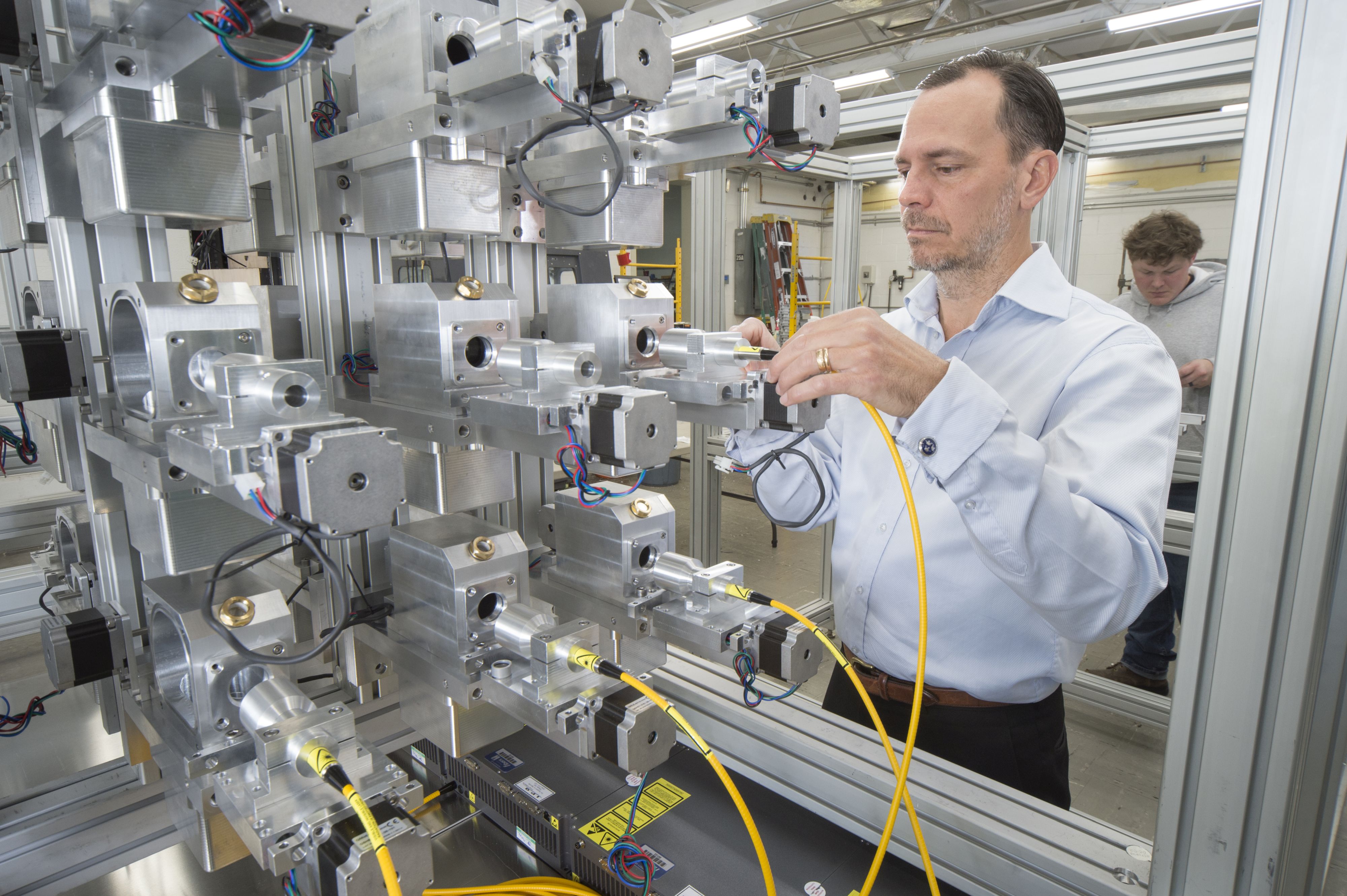
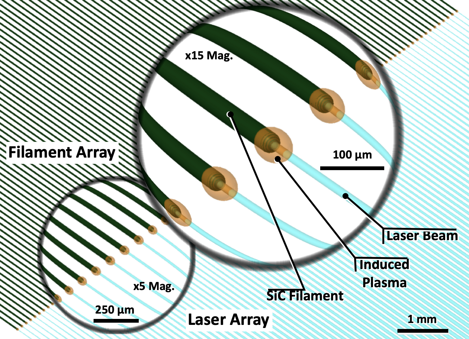
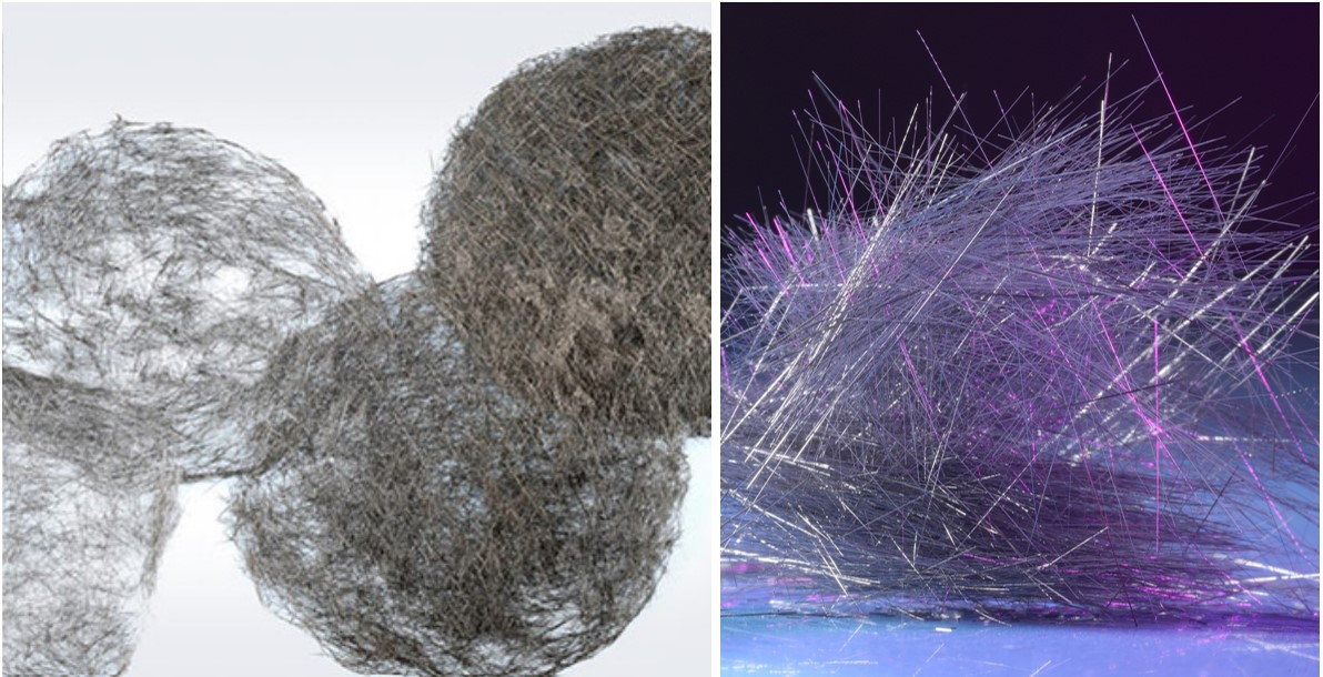
Figure 4. Laser CVD, scaling short SiC fiber production. Free Form Fibers’ patented single production tool (top) comprises 9 individual reactors, each using a multiplex laser to grow arrays of 50-100 SiC fibers up to 1.5 inches long (center), which can be used as nonwoven mats (bottom). Current gen2 production tools have 24 heads and gen3 production tools are being developed. Photo Credit: Free Form Fibers
How is the FFF process different from more conventional CVD? “Instead of heating up the entire volume inside a reactor and then introducing gases that deposit solid material onto a filament,” says Harrison, “we’re delivering the energy to decompose the gases in a focused laser beam onto a substrate, which initiates the breakdown of the gases to form solid SiC (Fig. 4). We’re basically growing the fiber by moving the substrate and the laser, to continuously deposit solid material.” Another difference is the reactor size. “It’s a little bit bigger than my fist,” says Harrison. “We have a very low CAPEX, but we use high-purity inputs and have developed our process to produce very high-quality fibers.”
CVD is indeed renowned for producing very pure SiC materials, but also for being glacially slow. “For typical hot wall CVD, the coating thickness onto the filament core drives the pull through rate of the fiber,” says Harrison. One industry source quotes production rates of 0.1 to 10 inches per minute for this process. “Yes, but that is for production of a single fiber,” notes Harrison. “We multiplex the laser so that we grow arrays of 50-100 fibers simultaneously. Even at the bottom end of that scale, we are producing 50 fibers at 1.25 inches long in approximately 10 minutes — which is effectively a production rate of more than 6 inches of fiber per minute. And we have scaled that to make kilograms of fiber per month. We then further scale by adding reactors, which are not expensive. So, our approach does have an economic basis to be not just competitive, but actually get to lower price points once we are at high-volume.”
FFF is maturing the technology now from lab to production scale. “We have built our first production tools, which are running 24/7 and we’re making material that we’re selling to customers. We’re on track to double our production capacity by the end of this year,” says Harrison. What are the targeted applications? “We’ve seen a lot of movement over the last year in ceramic-based additive manufacturing (AM), and that’s where having the discontinuous fiber has become an advantage. But we’re also looking at other material formats. We’re working with a partner to convert our fiber into a nonwoven mat, a format that is easily infiltrated with matrix, which reduces porosity, and also provides fibers in the Z-direction, which helps prevent delamination. We’re also developing relationships to look at turning our short fibers into a yarn that simulates continuous tow, in response to customers who still want that type of product.”
In addition to SiC, FFF is also looking into UHTCMC aimed at hypersonics applications. “One of these is silicon nitride (Si3N4) fiber for electromagnetic applications, which is desired but not yet available,” says Harrison. “We’re working through a DOD program to get that to a point of commercialization.” He notes that CMC is becoming a larger part of material solutions for an array of advanced applications, including nuclear energy, where the company is also active. “We want to be a manufacturer that supplies customers with real quantities of material for the higher end of temperatures in these applications,” he continues. “We think we have a good product that the market needs. We need to prove that and scale up, but we have good technology that has benefits and we’re going to be able to deliver that at a volume and price that matters to the CMC market.”
U.K.’s “Ceramic Valley” and NCC
The National Composites Centre (NCC, Bristol, U.K.) has also seen increased demand for CMC. In August 2023, NCC announced its partnership with Lucideon (Stoke-on-Trent) to develop advanced CMC solutions. NCC will lead system and product design, plus industrial scale-up. Lucideon will provide analysis, evaluation and access to the new AMRICC Centre (Staffordshire), which it hosts and has developed with Stoke-on-Trent as a key part of the area’s “Ceramic Valley.” AMRICC includes the National Advanced Sintering Centre which focuses on flash, cold, microwave and SPS technology and includes a project to use novel sintering and AM to innovate CMC for aerospace engines.
U.K. aeroengine manufacturers do indeed support CMC development at NCC, including the AFP-CMC Core project with partners Rolls-Royce (London), Reaction Engines (Abingdon) and missile manufacturer MBDA (Stevenage). In 2022, NCC successfully demonstrated manufacturing of an oxide CMC part using automated fiber placement (AFP) of 3M Nextel prepreg (see “Leveraging towpreg to reduce the cost of CMC”). Follow-on goals included to optimize AFP parameters for more complex geometries and to investigate, with 3M’s help, wider material formats to reduce the number of joints between tape courses for higher performance.
NCC has also worked with universities to develop UHTCMC that can withstand temperatures up to 2,000-3,000°C and is working to mature extrusion-based 3D printing and other AM. Another key program is HASTE-F, where NCC and the UK Atomic Energy Authority (UKAEA) report they’ve developed a step change in SiC/SiC manufacturing that reduces cost to one-fifth that of current CVI methods while achieving 95% density (versus 75% for CVI) and shorter cycle times plus more complex geometries and thicker sections. NCC claims such SiC/SiC components have the potential to double the electricity generated from every gigawatt of heat produced compared to fusion reactors using advanced steel designs. This is possible because a SiC/SiC breeder blanket, and the coolant within it used to extract energy from the reactor, can withstand higher temperatures up to 900-1,000°C — at the upper end of current R&D metal breeder blankets. This allows more efficient generator approaches to be used. NCC adds that it is pioneering industrialization of U.K. SiC/SiC design, modeling, manufacturing and technology capabilities to support the STEP (Spherical Tokamak for Energy Production) program aiming to construct the first grid-connected fusion reactor by 2040.
New CMC developments
Microwave-assisted CVI
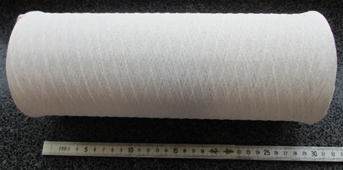
Photo Credit: CEM-WAVE project
The CEM-WAVE project (2020-2024) aims to produce novel CMC parts using a microwave-assisted chemical vapor infiltration (MW-CVI) process to reduce production time and cost. For example, the University of Birmingham in the U.K. reduced multiple cycles totaling 1,000 hours to a single 100-hour cycle for SiC/SiC parts. CEM-WAVE has produced tubular preforms using filament winding of Nextel 610 fiber with an aluminum phospate (AlPO4) coating and a zirconium matrix which will be sintered in equipment modified by Archer Technicoat Ltd. (ATL, High Wycombe, U.K.). Coatings have been developed by Fraunhofer ISC (Bayreuth, Germany) to help the largely microwave-transparent alumina fibers and matrix to absorb microwaves.
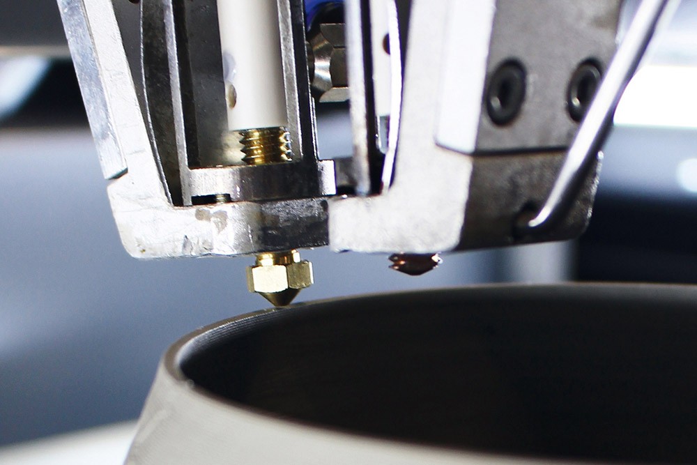
Photo Credit: Fraunhofer IKTS
3D-printed CMC
Fraunhofer IKTS (Dresden, Germany) has developed a fused filament fabrication process for ceramics (CerAM FFF) which uses homogeneous, highly filled thermoplastic filaments with a diameter of 1.75 millimeters. They are melted and deposited by the printhead and and then densified using PIP to form the CMC. This process offers the possibility to integrate ceramic fibers into the filaments, enabling AM of short to long fiber-reinforced CMC. A variety of ceramic matrices have been demonstrated and SiC/SiC components are in development.
DITF oxide fibers ramping to industrial scale
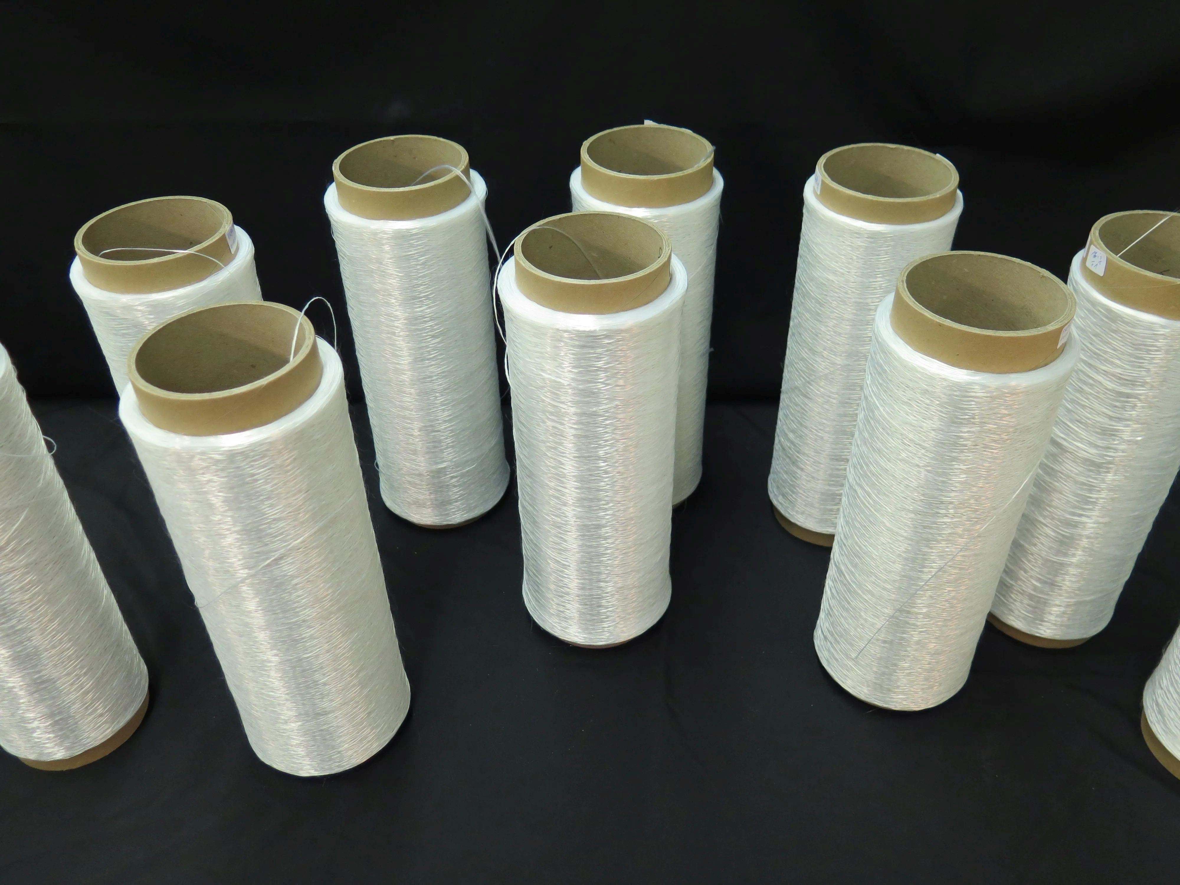
Photo Credit: DITF (Deutsche Institute für Textil + FaserForschung)
Having developed oxide fibers since 1990, DITF is now in partnership with Saint-Gobain for the industrial production of alumina (OxCeFi A99) and mullite (OxCeFi M75) fibers, scheduled to start in 2025. DITF fiber R&D continues, aiming at even better properties using multi-phase systems and elements such as Zirconium (Zr) and Yttrium (Y), with pilot production of Zr-toughened alumina (OxCeFi ZTA) and Zr-toughened mullite (OxCeFi ZTM) fibers already well advanced.
New UHTCMC
The C3HARME project (2016-2020) aimed to develop novel UHTCMC materials for hypersonic and space applications. Coordinated by CNR-ISTEC (Faenza, Italy), the project included partners such as Airbus, Ariane Group, Avio, DLR and others. Subscale rocket nozzles using short and long carbon fiber were fabricated and densified using SPS for densification and tested to technology readiness level (TRL) 6. TPS plates were also made using 2.5D carbon fiber preforms impregnated with zirconium diboride-alumina (ZrB2) slurry and converted using radio frequency-assisted CVI. Such TPS was tested to TRL 5. The C/ZrB2 UHTCMC materials developed in C3HARME were patented by CNR-ISTEC and have been commercialized by spinoff company K3RX.
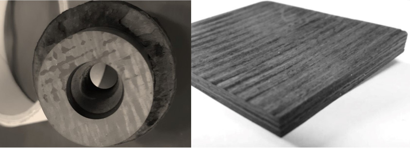
UHTCMC nozzle and plate. Photo Credit: K3RX
Filament-wound, laser-sintered CMC
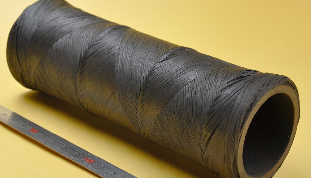
Photo Credit: Fraunhofer IKTS
Fraunhofer IKTS produced SiC/SiC parts using filament winding with an integrated laser system for sintering. This eliminates the need for post-winding sintering in a furnace. “We showed the feasibility of the laser process and built a simple CMC tube as a demonstrator. However, the part strength was not sufficient for industry applications,” says Clemens Steinborn, testing laboratory manager and researcher at Fraunhofer IKTS. “We are pursuing funding for a follow-up project to reach a higher TRL.”
Robot-sprayed short fiber OCMC
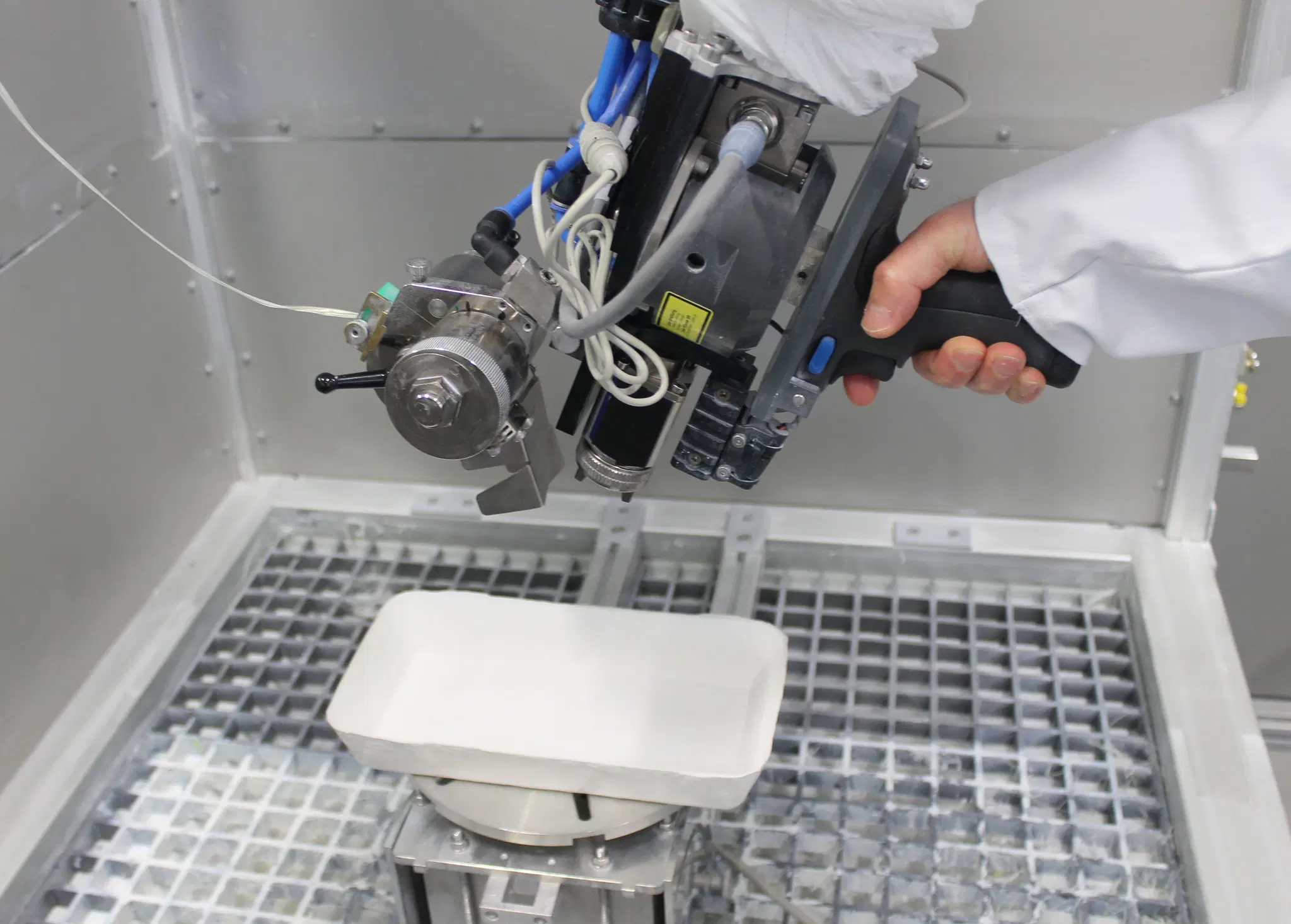
Photo Credit: University of Bayreuth
The University of Bayreuth is researching the production of oxide CMC using short fibers (14-60 millimeters long) in the FlexFiber project (2023-2026), funded by the German Research Foundation (DFG). The goal is a robot system that can be operated flexibly and intuitively by technicians.
Continuous fiber coating
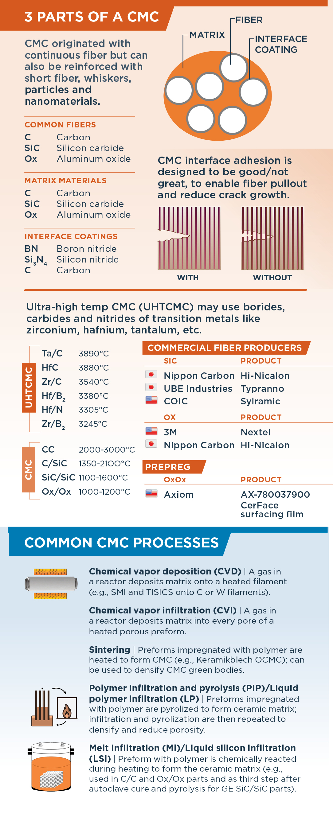
Another key CMC technology being developed in the U.K. is continuous coating of SiC fiber. “There are three main parts to a CMC — the fiber, the interface coating and the matrix,” explains John Yeatman, managing director of Archer Technicoat Ltd. (ATL, High Wycombe, U.K.). “For nearly all CMC, at the moment, the interface coating on the fibers is produced using CVD. Typical coatings include boron nitride, silicon nitride or a plain carbon interface.” ATL has provided advanced coating solutions for 40 years and interface coating for CMC for 20 years. “We perform R&D, design systems, build and sell coating equipment and also provide coating services,” says Yeatman. “Most of the latter has been using batch processes, where you take your woven fiber, preform or layup and put it in a mold, and then you’ll infiltrate it using CVI and put the coating on that way. We say CVI instead of CVD if we’re coating all of the surfaces in a porous preform.”
“But there are also continuous coating methods,” Yeatman continues, “where you coat the fibers before layup. As long as you can make the coating both stable and flexible — so that you can handle the coated fiber and lay it up — then it has obvious advantages in efficiency. Pioneered mostly by GE, this is used in its industrial-scale CMC production. But that technology is restricted, so nobody else in the world has access to it.” Yeatman says ATL’s goal is to develop continuous coating capability for CMC fibers that can be used by pretty much anyone, especially companies outside the U.S.
This was the goal for the Continuous Interface Coating for Silicon Carbide composites (CICSiC) project, led by ATL. “The CICSiC project allowed us to design and build a prototype piece of coating equipment, operate it and test it. And it’s been very successful,” says Yeatman. The U.K. project partners included the University of Sheffield Advanced Manufacturing Research Centre (AMRC, Rotherham), Cygnet Texkimp (Northwich) and TISICS (Farnborough). “Cygnet provided the fiber handling expertise that could help us run the fiber back and forth through the furnace,” says Yeatman. “You have to control the tension and speed, which is quite tricky, because the fibers are very fine, easily abraded and broken.” TISICS also provided fiber handling expertise and helped design a specific aspect of the coating equipment, while AMRC tested the flexibility of the coated fiber.
With CICSiC completed, ATL is seeking a follow-up project to accelerate the final development needed. “Although the machine works well, and we’re using it, you can only put a single coating on when you pass the fiber through the furnace,” explains Yeatman. Multiple coatings are typical, he adds, and used by GE, for example. “Each layer has a separate function, be it as a diffusion barrier, debonding [good not great interface] or oxidation resistance. For now, if you want a multi-layered coating, you have to wind it through one way and then wind it back through the other way. So, we need to improve our fiber handling for this and also to enable longer runs. We want to get to a point where we can build a piece of equipment with multiple coating stages that we can sell, so our customers will be able to produce their own coated fibers.”
Customers interested in this technology include the major aerospace companies outside of the U.S. and a growing supply chain to produce SiC fibers in Europe. “But there is now an operation in Germany and one of the ideas is to basically add coating as a part of the fiber production process,” says Yeatman. “Just put a CVD system on the end, so that as the fiber comes off the production line, it gets coated, continuously straight away. And to me, the potential that could have has already been proven.”
Needs for expanded CMC future
When asked what is needed to increase the use of CMC, Ceramic Composites network’s Schüppel says it varies by each of the four major types. “Industry is looking for reactor tubes that also have good thermal shock resistance. For Ox/Ox, the challenge is to get CMC parts dense enough to hold gases.” For SiC/SiC, he notes GE has fiber, coating and parts production all in-house. “The challenge is that European SiC fiber producers don’t necessarily have that know-how in coatings and their interaction with the SiC matrix nor in the intricacies of CMC parts production.” To expand C/SiC applications, says Schüppel, “simulation is needed to create a virtual twin along the entire process chain. This will help reduce trial and error, and thus cost. For C/C, aircraft brakes are the largest market. Safran has said it is researching new CVI. The challenge is to get high-quality parts but also meet targets for less energy, cost and carbon footprint.”
Indeed, sustainability of CMC is a nascent, but growing topic. For a discussion of energy use, lifecycle analysis and bio-based materials, watch for our upcoming digital article: “Increasing the sustainability of CMC.”


Related Content

Low-cost, efficient CFRP anisogrid lattice structures
CIRA uses patented parallel winding, dry fiber, silicone tooling and resin infusion to cut labor for lightweight, heavily loaded space applications.
Read More
Plant tour: Airbus, Illescas, Spain
Airbus’ Illescas facility, featuring highly automated composites processes for the A350 lower wing cover and one-piece Section 19 fuselage barrels, works toward production ramp-ups and next-generation aircraft.
Read More
Composites end markets: New space (2025)
Composite materials — with their unmatched strength-to-weight ratio, durability in extreme environments and design versatility — are at the heart of innovations in satellites, propulsion systems and lunar exploration vehicles, propelling the space economy toward a $1.8 trillion future.
Read More
Carbon fiber composite pallet revolutionizes freight industry
LOG Point Pallet fuses advanced materials with innovative design and manufacturing to improve supply chains worldwide.
Read MoreRead Next

RATH prepares for production of advanced oxide ceramic fiber for CMC
New facility in Germany is part of regional supply chain and vision to lead green energy transition using CMC, supported by German government and Composites United’s Ceramic Composites network.
Read More
Plant Tour: GE Aviation, Asheville, NC, US
An avant-garde approach to unprecedented CMC parts production.
Read More
Vertically integrated CMC supply chain
GE Aviation's new ceramic matrix composite supply chain includes fiber, prepreg and unprecedented parts production facilities, plus a strongly tied 4-bump development stream.
Read More