
The Picture Frame Shear Test method
Dr. Donald F. Adams (Wyoming Test Fixtures, Salt Lake City, Utah) reviews the history of the Picture Frame Shear Test method.
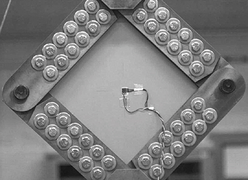
Fig. 1: A typical Picture Frame Shear Test fixture used for testing solid laminates. Source: Don Adams
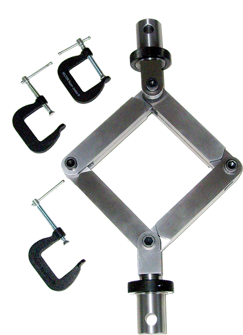
Fig. 2: Simple Picture Frame Shear Test fixture. Source: Don Adams
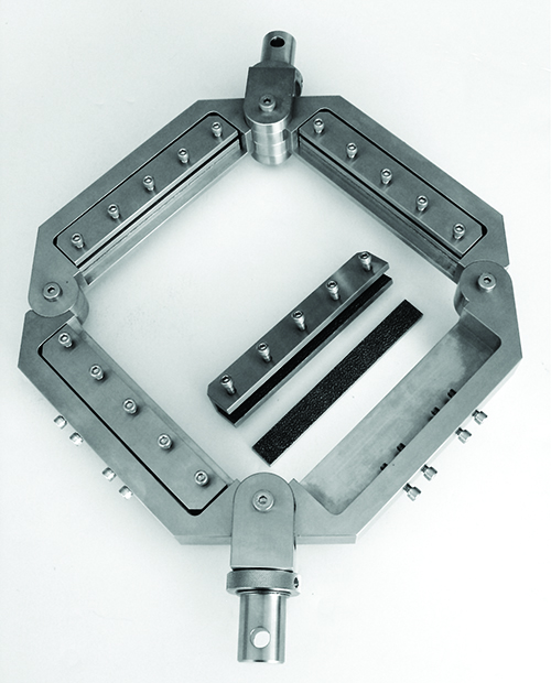
Fig. 3: Picture Frame Shear Test Fixture with strand-straightening mechanism. Source: Don Adams


The picture frame shear test method achieved some popularity in the early days of composite materials development when few other shear test methods existed. But as the two- and three-rail shear test methods, and later the Iosipescu shear test, were introduced for characterizing basic shear properties, picture frame shear testing became less popular for three reasons: It used a relatively large specimen; test preparation required that a number of holes be drilled in the specimen; and the method required a complex fixture. Despite these disadvantages, the picture frame shear test continued to be an attractive option for composite laminate panel testing because the method accommodates large specimens.
A fixture similar to that shown in Fig. 1 (see images at left) has long been in use. As noted above, a series of holes are drilled in each of the panel’s four edges. The required number of holes depends upon panel strength and thickness. The hole pattern matches that of the four pairs of fixture rails. Bolts are then used to clamp the panel edges between the rails. The rail surfaces that come into contact with the specimen may be coated with tungsten carbide particles, or otherwise roughened, to increase their gripping effectiveness. The four corners of the fixture are pinned, allowing the pairs of rails to rotate relative to each other. During the test, the panel is subjected to shear by applying a pulling force to diagonally opposed corners of the fixture’s frame.


When the method is used to test relatively low-strength composite panels, it might be possible to simplify both the specimen and the fixture. An example of a simple fixture is shown in Fig. 2. No bolts are used, so drilling is unnecessary. The pairs of rails are joined using C-clamps, with the panel sandwiched between them. Alternatively, clamps can be integrated into the fixture rails. Here, too, the rail surfaces may be coated with tungsten carbide particles or roughened to enhance gripping.
Despite its long history, the picture frame test has not yet been the subject of an ASTM International (W. Conshohocken, Pa.) published standard. But today, as designers turn increasingly to composite sandwich panels in many applications, picture frame shear testing is attracting renewed attention. In response, a draft standard is now being developed by ASTM Subcommittee D30-09 on Sandwich Construction. It will use a test fixture similar to that in Fig. 1, but with a single row of fasteners along each edge.
Beyond sandwich panel testing, an even greater motivation for picture frame fixture development is its utility in determining the shear properties of dry reinforcement fabrics and uncured fabric prepregs. The purpose is to determine the material’s drapeability during layup procedures. The material must smoothly conform to the mold’s three-dimensional surface without wrinkling. The fabric achieves this primarily by the rotation of the fiber bundles relative to each other at their crossover points, which is a shear process. The practical limit of this shear deformation is reached when the fiber bundles rotate so far that they begin to interfere with each other, defining the lock angle of the fabric. Thus, shear is the appropriate simulation mode, and a picture frame shear test is a suitable method for applying the shear force.
There are alternative methods for determining drapeability. The specimen can be subjected to opposing in-plane forces at, and parallel to, two opposite edges, much like the loading of the two-rail shear test method for solid composite laminates (ASTM D 4255). However, this so-called Direct Shear Force Loading induces tensile stresses throughout the dry fabric or prepreg, in addition to nonuniform shear stresses. Because it is difficult to separate the contributions made to fabric deformation by the shear and tensile stresses, the accuracy of this test’s result is questionable.
Another technique, favorable for its simplicity, is the Bias Extension method. The fabric is oriented at ±45º and subjected to a simple in-plane tensile loading (that is, a biased loading), much like that applied in the ASTM D 3518 in-plane shear test for composite materials. No fixture is required — just tensile grips. To generate a central zone of shear stress, a specimen at least twice as long as its width must be used, so that none of the fiber bundles in the specimen’s central region are held in the grips at either end. But because the quantity of interest is the shear force required to cause a given shear deformation (i.e., fiber bundle rotation), this test, too, is problematic. Even the fiber bundles in the central region carry some tensile load due to sliding friction between bundles. Again, separating the force required to create the shear rotations from the sliding friction forces of the fiber bundles is difficult so the result could be unreliable.
Given the above, the picture frame method is preferred for determining drapeability. But one practical challenge, especially with dry fabrics, is properly gripping the specimen. In theory, all of the fabric strands should be gripped and loaded uniformly because there is minimal force transfer between strands to aid in load redistribution — force transfer is high when testing a composite laminate. Ideally, the strands should be equally straight before the test begins. Practically, this can be achieved to a degree as the load is applied: those strands that are straightest and, thus, carry a greater portion of the load, slip in the grips, redistributing the load. Unfortunately, the loads required to shear the dry or prepregged fabric are not high, so the tensile loads carried by these strands will distort the test result. Some improvement in load uniformity can be achieved by applying multiple preliminary loadings prior to that for which deformation measurements are made.
The fixture in Fig. 3 exemplifies one attempt to straighten fibers prior to testing. The fabric or prepreg is carefully aligned and lightly clamped between the rails (coated with 36-grit tungsten carbide), and then the clamps are moved outward, using the adjustment screws on the fixture’s four sides. Because the specimen is lightly clamped and the displacements are in the strand directions, tight strands slip and slack strands straighten. When acceptable alignment is achieved, the clamping screws are fully tightened.
Although it doesn’t straighten fibers, another grip design has rail pairs with mating wavy surfaces perpendicular to the strand direction, forcing the clamped strand end down into the troughs to create a more torturous pullout path.


Related Content

Corebon induction heating
This sidebar to CW’s August 2024 feature article reviews this technology for more efficient composites manufacturing and why it aligns with Koridion active core molding.
Read More
Active core molding: A new way to make composite parts
Koridion expandable material is combined with induction-heated molds to make high-quality, complex-shaped parts in minutes with 40% less material and 90% less energy, unlocking new possibilities in design and production.
Read More
ASCEND program completion: Transforming the U.K.'s high-rate composites manufacturing capability
GKN Aerospace, McLaren Automotive and U.K. partners chart the final chapter of the 4-year, £39.6 million ASCEND program, which accomplished significant progress in high-rate production, Industry 4.0 and sustainable composites manufacturing.
Read More
Testing to support composite bolted joint analysis
An overview of ASTM Standard Guide D8509, and its coupon-level mechanical testing of design properties for analyzing composite bolted joints.
Read MoreRead Next

Ultrasonic welding for in-space manufacturing of CFRTP
Agile Ultrasonics and NASA trial robotic-compatible carbon fiber-reinforced thermoplastic ultrasonic welding technology for space structures.
Read More
Cutting 100 pounds, certification time for the X-59 nose cone
Swift Engineering used HyperX software to remove 100 pounds from 38-foot graphite/epoxy cored nose cone for X-59 supersonic aircraft.
Read More
Ceramic matrix composites: Faster, cheaper, higher temperature
New players proliferate, increasing CMC materials and manufacturing capacity, novel processes and automation to meet demand for higher part volumes and performance.
Read More