
.jpg;width=70;height=70;mode=crop;format=webp)


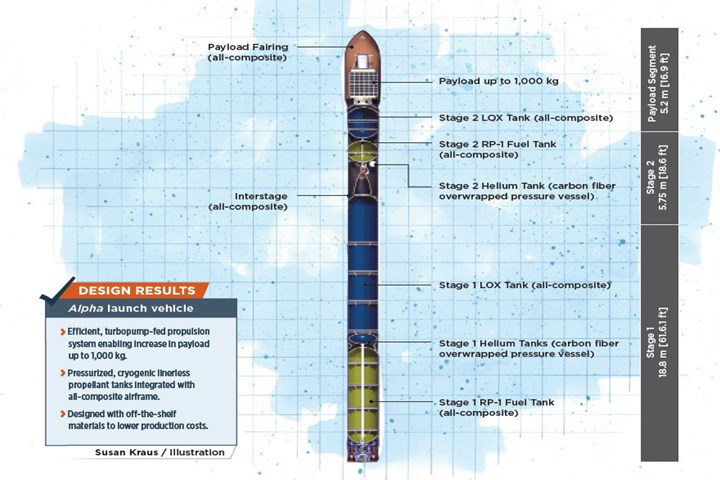
Alpha 2.0 launch vehicle illustration. Photo Credit: CW
Firefly Aerospace’s (Austin, Texas, U.S.) all-composite Alpha small-satellite launch vehicle is scheduled for its first launch by the end of 2020. The rocket, which is designed to launch satellites for customers into orbit, was originally conceived by Firefly Space Systems (Austin), which filed for bankruptcy in 2017. The intellectual property and assets of Firefly Space Systems were subsequently purchased by Dr. Max Polyakov’s Noosphere Ventures (Menlo Park, Calif., U.S.), which recapitalized and reopened it as Firefly Aerospace the same year.


According to John Courter, director of structures at Firefly Aerospace, the temporary closure and rebooting of the company provided “an inflection point” in which to perform additional market research and re-imagine the Alpha rocket. The original Alpha vehicle was an all-composite, 6-foot-diameter rocket, with a payload capacity of 300 to 500 kilograms. In the reopening, the company decided that the new version of the launch vehicle, which can be referred to as Alpha 2.0, would be viable in the market only if it could carry a 1,000-kilogram payload, filling a need for launching mid-sized satellites to low Earth orbit (LEO).
In addition to increasing Alpha’s payload capacity, according to Jeff Duncan, Stage One airframe engineer, one of Firefly’s goals, for Alpha and for the company overall, is to take scientifically proven rocket technology and evolve it into a high-performance, relatively low-cost system (Alpha, for example, costs about $15 million USD per launch).
Accordingly, Firefly Aerospace has spent the past three years designing, building, testing and qualifying the Alpha 2.0 rocket.
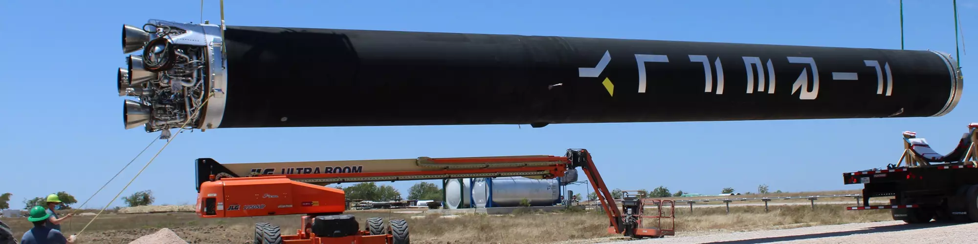
Putting Alpha to the test. The Stage One system for Firefly Aerospace’s Alpha 2.0 small launch vehicle sits on the company's test stand at its Austin, Texas, U.S., facility. Photo Credit: Firefly Aerospace
Designing Alpha 2.0
The United States government’s Air Force Space Manual 91-710, says Courter, outlines the qualification standards and safety requirements for launch vehicles within the U.S. “It tells you a lot of what you need to do to build a rocket, and it gives you some baseline for what you’re doing,” he says. However, according to Courter, most of the guidelines and qualification documents are written for metallic rockets. “There’s no document that tells you how to build a composite rocket,” he says. Regardless, a composite rocket seemed the obvious choice given Firefly’s composites design and manufacturing experience, along with goals to increase payload capacity for Alpha without increasing the diameter (the 6-foot diameter is ideal for transport), and to keep the overall weight as low as possible.
The first step to designing a rocket that met all of Firefly's goals, Duncan says, was figuring out what shape the rocket was going to take.
Alpha 2.0, standing at 29 meters (95 feet) tall in total, comprises a two-stage structure. Topping the rocket is the newly enlarged payload segment, made up of a 2-meter (6.6-foot) diameter carbon fiber composite payload fairing covering the payload storage area. Beneath the payload fairing, the cylinder of the rocket is divided into two stages: Stage Two, directly under the payload fairing, is the smaller stage, at 6 meters long (19.7 feet). Stage One, at the bottom of the rocket, is longer at 18 meters (59.1 feet). Both stages comprise an exterior composite airframe and, inside, the oxygen, fuel and helium tanks, and avionics systems. Stage One is designed to launch the rocket into space from the ground, but eventually separates from Stage Two, which carries the payload into LEO.
To power the Alpha 2.0 rocket design, Firefly also decided to build the new launch vehicle with a higher-thrust, more efficient propulsion system, which enabled weight reduction and optimization of the overall structure. The original design included a pressure-fed propulsion system — which relies on high-pressure propellant tanks to force fuel into the combustion chamber.With Alpha 2.0, Firefly switched to a more efficient, turbopump-fed propulsion system that replaces the high-pressure tanks with motorized pumps. The change to a lower-pressure system, Courter says, allowed for a redesign of the overall rocket structure itself, from a “carbon overwrapped classic pressure vessel-esque design” in which the pressurized propellant tanks were completely separate from the airframe and other unpressurized structures, to a “carbon monocoque design” in which the tank and airframe are integrated into one continuous structure.
“In Alpha 2.0, we don’t use a carbon overwrapped pressure vessel because it’s much lower pressure. Instead, we have what the industry would call a pressurized structure,” Duncan explains. “When we integrate the airframe, the unpressurized sections of the vehicle are combined with the pressurized sections of the vehicle into a continuous structure. We call it our carbon monocoque airframe or carbon monocoque architecture.” This design, Courter says, enabled significant weight reduction for the rocket.
Courter explains that the design of Alpha 2.0 has been an iterative process between design/analysis and testing. “Our approach is that we make it, break it, make it, break it, make it and then fly it. We find what our own failure mechanisms are, we iterate to remove those from the equation and then we go again,” he says.
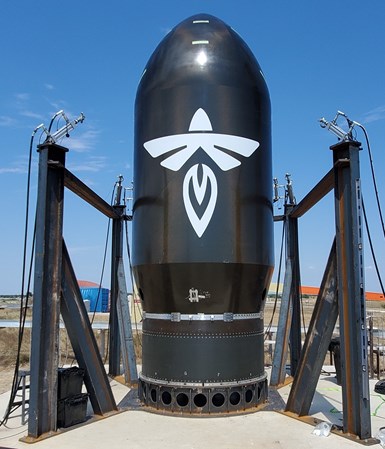
Increasing payload. The payload section of the Alpha 2.0 launch vehicle is designed to carry up to 1,000 kilograms of payload into low Earth orbit. Firefly Aerospace is also working on a larger version of Alpha, called Beta, to carry more than 7,000 kilograms. Photo Credit: Firefly Aerospace
Along with structural and load requirements, core design considerations included safety, cryogenic tank temperatures and reproducibility. Alpha was designed in a “scaled approach,” Courter adds, “meaning we designed our Stage Two first, as [it] had smaller tanks, lower loads and the cost of development (and failure) were much lower. Once we optimized that system, we scaled our approach up to make the Stage One systems.”
“When it comes to designing the rest of the rocket, we largely tried to stay as simple as possible,” Duncan says, “and make [the structures] as simply and inexpensively as we can while still being able to execute the mission and maintain the high-performance structural requirements and mass requirements.”
To produce the structures, Firefly defined the tool geometry using Autodesk (San Rafael, Calif., U.S.) Inventor software. The ply schedule and orientations were subsequently mapped and combined with the simulated mold shape to model the full structure, using ANSYS (Canonsburg, Pa., U.S.) software.
Material selection and manufacture
Step two, Duncan says, was material selection. In designing Alpha 2.0, Firefly Aerospace performed trade studies to compare the performance of composite versus metallic structures, and found significant weight savings with composites. “With these smaller classes of vehicles, the rocket’s just not that big and it’s limited by how much mass it can carry, and so you need the lightest airframe possible,” Duncan says.
Firefly decided on an all-carbon fiber prepreg construction, simply, Duncan says, because of its wide availability in the market. “I mean, just making a composite rocket was a big enough challenge, without having to reinvent the material systems to get there,” he says. “We wanted to find commercially available materials to help reduce the cost of [the rocket].”
Firefly did material testing with a variety of commercially available resin and fiber systems, assessing them to see which would be most effective for Alpha’s requirements — especially, Courter says, given the cryogenic requirements of the rocket propellant tanks.
The goal is to scale up production to a targeted 24 rockets per year, which is expected to take place by the end of 2022.
“Ultimately, we came up with a partner that was going to help get us to space,” Courter says. Currently, Firefly Aerospace constructs the composite structures on its Alpha rockets from Toray (Tokyo, Japan) carbon fiber prepregged with a proprietary epoxy resin system.
The smaller, helium and nitrogen tanks are filament-wound, metal-lined composite overwrapped pressure vessels (COPV); most of the other structures are completely composite, including all Stage One and Stage Two RP-1 fuel and liquid oxygen tanks, interstage, intertank, payload fairing, payload attachment fittings, payload skirt and various unpressurized structures.
Courter notes that, once the initial design was created and simulated virtually, the tooling could be built, which was a challenge in itself. To save costs, the team manufactured most of the rocket’s composite structures on multiple smaller, static tools and then joined the pieces together to build the full rocket.
All of Firefly’s composite structures are manufactured out of autoclave (OOA) using hand layup with vacuum-only compaction and oven cure. This decision was partly made due to the high expense of purchasing an autoclave, but mostly, Duncan says, Firefly knew it had to use an OOA approach if it ever wants to build even bigger rockets than Alpha 2.0 someday.
Four phases to test and launch
Between the first design conversations and the final flight-ready rocket, there are essentially four rockets that need to be built, Courter explains: A development rocket, a qualification rocket, a stage qualification rocket and the flight rocket.

Rocket fuel. An RP-1 fuel tank for Alpha's Stage One sits at Firefly Aerospace’s test stand. Photo Credit: Firefly Aerospace
“The first, [demonstration] rocket wasn't meant to be fully assembled,” Courter says. “It's a manufacturing demonstration of concept.” The development units are built quickly and early in the process, and “show you what manufacturing processes are robust, and which ones need to be fixed.” The qualification rocket is built for testing — and not just the structure, but the avionics, software and propulsion system as well. Testing is done at Firefly’s Texas facilities and includes a variety of burst tests, squeeze tests and other assessments to ensure each individual structure can withstand more than the required load and pressure. The stage qualification rocket is what gets qualified for flight-readiness. This is where the fully assembled rocket is tested against the U.S. Air Force standards for safety. Finally, the flight rocket is ultimately the one that will launch to space.
As issues arose at each phase, designs and processes were adjusted, tanks went through multiple iterations and, ultimately, lessons were learned. “We replaced major components, we changed the engine, broke the tanks, changed the tanks,” lists Lawrence Goedrich, Stage Two responsible engineer. “We teased out a lot of failure … and we took all those lessons and we applied them [to the next iteration].”
Courter sums up the process: “Every part of the rocket … [goes] through the same design process, where you come up with your initial constraints, your compliance matrix, your requirements, how you come up with your materials and how you're going to build it. You figure out what the big pieces are and how they're going to go together. You go through that design, analysis and iterative optimization. Then you do the tooling, you qualify it, you do the acceptance. And then you're clear to fly.”
Design challenges
According to Duncan, the most challenging structure to design on the rocket was also the largest, coldest and held the most flammable fluid onboard the rocket: The 7,000-gallon, 31-foot-long, cryogenic liquid oxygen (LOX) Stage One tank. Each of the two stages of Alpha 2.0 surrounds a LOX tank containing the oxidizer for the propulsion system. Each tank is maintained at a specific pressure for Firefly’s propulsion system, and cooled to -300°F (-149°C). Goedrich adds, “this will be the largest operational carbon composite propellant tank system that we know of.”
On the original, smaller Alpha 1.0 rocket, the LOX tanks were built from filament-wound, composite-lined COPVs. This type of typical, industrial tank, Duncan says, allowed for the higher pressures required of a pressure-fed rocket. However, the lower-pressure turbopump-fed propulsion system on Alpha 2.0 enabled Firefly to shift to a linerless, Type V tank integrated with the rocket's airframe. “We jokingly call it a ‘liner-only’ tank, as in a composite-liner only, which really just means a thin laminate,” Duncan says.
Another major challenge, Duncan says, was figuring out how to join the interior tanks to the exterior airframe. Firefly decided that traditional fasteners presented too many challenges, but the company could not find an off-the-shelf adhesive that was durable enough to bond the major rocket joints while withstanding the LOX tanks’ cryogenic temperatures. “You need a glue that’s highly elastic, and there are just not many out there,” Duncan says. The team has since developed a proprietary assembly method to meet its requirements.
Scaling up with automated fiber placement
Once the rocket system has proven successful for flight, the goal, Courter says, is to scale up production to a targeted 24 rockets per year. Firefly expects to have necessary systems in place by the end of 2021, with high-scale production to begin in 2022. At full-rate production, Firefly will have about two weeks to manufacture and test all rocket components.
To meet such an aggressive schedule, Courter says, manufacturing methods need to be optimized. The low-rate development rocket structures were built with hand layup and soft-cut tooling, “but as we go forward, there is way too much touch labor involved, and it’s a variable process” with too much room for human error. With the recent purchase of an automated fiber placement (AFP) machine from Ingersoll Machine Tools (Rockford, Ill., U.S.), Firefly intends to scale up its rocket production through automation.
“Firefly has been a very collaborative group to work with,” says Chip Storie, CEO of Ingersoll Machine Tools. “From the start, they told us exactly what the criteria were that they were going to evaluate, and they had some challenging things that they wanted to achieve, both technically and commercially, but knowing upfront what those goals were allowed us to put together a package to meet their needs for both complex parts and high rate of production.”
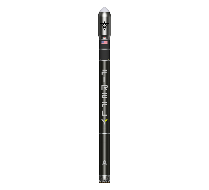
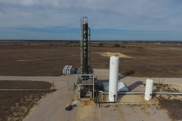
Ready for takeoff. A rendering of the full Alpha launch vehicle, expected to make its first launch by the end of 2020. Photo Credit: Firefly Aerospace
“With AFP, we’re able to put the same materials down [every time], we’re able to better tailor the system, and we can vary our quantities to put more fiber in a given direction if we need to,” Courter says. “We will be taking advantage of the steered fiber capability, which allows us to better optimize loads around structural penetrations, and complex shapes (like the payload faring) … and will allow us to greatly increase our capabilities in the future.”
Looking to the future, Firefly says Alpha 2.0 will be the baseline for a much larger, two-stage, 7,000+-kilogram payload Beta launch vehicle, which, along with Alpha 2.0, will be manufactured at the company's 70,000-square-foot composites facility in Austin that Firefly expects to be operational by the end of 2021, which will include a second Ingersoll AFP machine for additional production capacity.


.jpg;maxWidth=300;quality=90;format=webp)
Related Content

RUAG rebrands as Beyond Gravity, boosts CFRP satellite dispenser capacity
NEW smart factory in Linköping will double production and use sensors, data analytics for real-time quality control — CW talks with Holger Wentscher, Beyond Gravity’s head of launcher programs.
Read More
Materials & Processes: Tooling for composites
Composite parts are formed in molds, also known as tools. Tools can be made from virtually any material. The material type, shape and complexity depend upon the part and length of production run. Here's a short summary of the issues involved in electing and making tools.
Read More
One-piece, one-shot, 17-meter wing spar for high-rate aircraft manufacture
GKN Aerospace has spent the last five years developing materials strategies and resin transfer molding (RTM) for an aircraft trailing edge wing spar for the Airbus Wing of Tomorrow program.
Read More
Novel dry tape for liquid molded composites
MTorres seeks to enable next-gen aircraft and open new markets for composites with low-cost, high-permeability tapes and versatile, high-speed production lines.
Read MoreRead Next

Composites in the race to space
Advanced materials use in current and upcoming NASA missions.
Read More
Composites end markets: Energy (2024)
Composites are used widely in oil/gas, wind and other renewable energy applications. Despite market challenges, growth potential and innovation for composites continue.
Read More