
Testing the damage tolerance of composite materials
Dr. Donald F. Adams (Wyoming Test Fixtures, Salt Lake City, Utah) looks at standards and also-rans in the area of testing for damage tolerance.
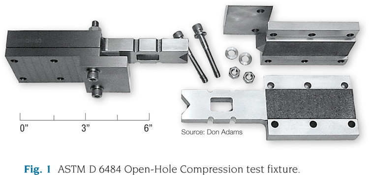
Fig 1: ASTM D 6484 Open-Hole Compression test fixture. Source: Don Adams
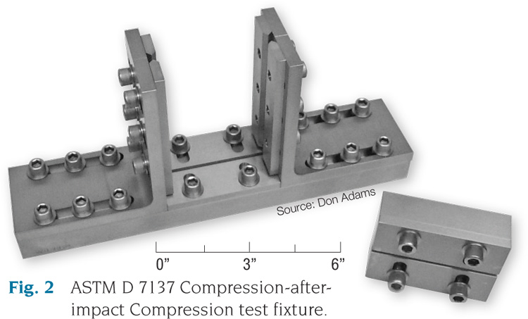
Fig 2: ASTM D 7137 Compression-after-impact Compression test fixture.


In the early 1980s, the limited damage resistance/tolerance of relatively brittle carbon/epoxy composite materials that had been available up to that time spurred development of toughened epoxies, bismaleimides, polyimides and high-temperature thermoplastics, such as PEEK, PPS and PAS. These materials enabled designers to extend composites to new applications while considering “the effects of defects,” which became a new catchphrase. But these enhanced properties in the new materials necessitated the development of corresponding new tests to quantify their damage resistance and damage tolerance.
Two categories of damage-tolerance test methods gained particular attention: open-hole and compression-after-impact. Each was developed somewhat independently in different forms by a number of industry and government groups. By 1990, several detailed approaches, and corresponding test-fixture configurations, had been published but the level of use in the composites community remained limited.


It was the well-defined and oft-quoted seminal publication by The Boeing Co. (Seattle, Wash.), “Advanced Composite Compression Tests,”1 that had the greatest influence. First published in 1982, it led to a number of subsequent Boeing documents, to the Suppliers of Advanced Composite Materials Assn.’s (SACMA) Recommended Methods SRM 3-88 and SRM 2-88, and to NASA Reference Publication 1092. Eventually, two new ASTM standards resulted. Since then, several European and ISO standards also have been written, following the same general procedures.
It was the publication of the ASTM standards that firmly established damage tolerance testing as a desired element in the characterization of composite materials. The first of the two is ASTM D64842, “Open-Hole Compressive Strength of Polymer Matrix Composite Laminates." The 300-mm/12-inch long, 36-mm/1.5-inch wide specimen contains a centrally located 6-mm/0.25-inch diameter hole, which is assumed to be an idealized defect, amenable to a corresponding stress analysis of the effect of this “defect” on structural performance. But actual structures also have deliberately induced holes and cutouts that provide internal access or accommodate fasteners. Therefore, this standard serves a dual role, and its use increased rapidly as it has become more widely known. Although a quasi-isotropic [0/±45/90]ns laminate is typically used, other layup configurations can be specified as well, if they are appropriate to the design application.
The Boeing/ASTM test fixture is shown in Fig. 1. Because the compression specimen is so long, the primary function of the test fixture is to prevent the specimen from buckling by constraining it between the fixture's flat plates. As originally conceived by Boeing, the fixture is gripped between large wedge grips, and the load is induced into the specimen by shear forces between the fixture and the specimen. But because the ends of the specimen and fixture are flush, the ASTM standard also permits direct end loading.
A similar test method, developed by the Northrop Corp.3 (Hawthorne, Calif.), uses a 76-mm/3-inch long, 25-mm/1-inch wide end-loaded specimen, also with a 6-mm/0.25-inch diameter hole and a somewhat different fixture configuration. Although it has been demonstrated that this alternate configuration yields similar results yet conserves specimen material, it has not been adopted by any standards group and, therefore, is not widely used.4
A carefully prepared round hole is relatively easy to replicate from specimen to specimen, but it may not be representative of the actual degradation of strength properties that can occur in a damaged structure. Damage often is induced by accidental impact and may be invisible, or barely visible, to the unaided eye.To simulate such damage, the Compression After Impact (CAI) test was developed, now standardized as ASTM D7137.5 Adapted from the original Boeing version, the quasi-isotropic specimen is 150 mm/6 inches long, 100 mm/4 inches wide and typically ~5 mm/~0.2 inches thick. After the specimen is subjected to a controlled impact-damage event, it is clamped over a rectangular hole in a baseplate and drop-weight impacted by a hemispherical-nosed tup that delivers a specified amount of energy, which typically induces visible but limited damage (see ASTM D7136).6 Then the specimen is subjected to inplane compression in the fixture shown in Fig. 2 while it is supported along all four edges and uniformly loaded along its shorter edges. The two long edges are supported by “knife edges,” and the supports along the short edges are actually flat surfaces, but the clamping forces are minimal.
An alternate CAI fixture was introduced by NASA7 about the same time as the Boeing original, using a 254-mm/10-inch by 127-mm/5-inch specimen. Because it consumed more specimen material than the Boeing method and its fixture has no obviously superior technical features, NASA's method never gained much popularity, even though the specimen size could have been sized like Boeing's.
Much more recently, Airbus SAS (Toulouse, France) has introduced a modification of the Boeing fixture, using the same specimen size and employing edge-constraint geometry, but providing for the application of positive clamping force on all four edges via clamping screws.8 Although this helps assure that positive contact is made with the specimen edges, the specimen's long sides are still “simply supported” by knife edges, and the clamping screws cannot provide enough rotational restraint to induce a “fixed” boundary condition on the short sides. Consequently, it is not obvious what technical benefit has been gained relative to the Boeing/ASTM fixture. That said, the Airbus fixture is gaining popularity, primarily among those who conduct testing for Airbus Industries.
No other damage tolerance test methods have been introduced in recent years, and none are on the horizon. Therefore, it is likely that the two existing Boeing/ASTM standards discussed here will continue to govern testing for some time to come.
Wyoming Test Fixtures Inc.
References:
1Boeing Specification Support Standard BSS 7260, “Advanced Composite Compression Tests,” The Boeing Co. (Seattle, Wash.), revised December 1988 (originally issued February 1982).
2ASTM D6484-09, “Open-Hole Compressive Strength of Polymer Matrix Composite Laminates,” ASTM International (W. Conshohocken, Pa.), 2009 (originally published 1999).
3Northrop Specification NAI-15604C, “Open Hole Compression Test Method,” Northrop Corp. (Hawthorne, Calif.), May 1988.
4Coguill, S.L., and Adams, D.F., “A Comparison of Open-Hole Compression Fixtures by Experimental Evaluation,” Proceedings of the 45th International SAMPE Symposium and Exhibition, Long Beach, Calif., May 2000, pp. 1095-1105.
5ASTM D7137-07, “Compressive Residual Strength Properties of Damaged Polymer Matrix Composite Plates,” ASTM International (W. Conshohocken, Pa.), 2007 (originally published 2005).
6ASTM D7136-07, “Measuring the Damage Resistance of a Fiber-Reinforced Polymer Matrix Composite to a Drop-Weight Impact Event,” ASTM International (W. Conshohocken, Pa.), 2007 (originally published 2005).
7NASA Reference Publication 1092, “Standard Tests for Toughened Resin Composites,” NASA-Langley Research Center (Hampton, Va.), Revised Edition, July 1983.
8Airbus Test Method AITM1-0010, “Determination of Compression Strength after Impact,” Airbus SAS (Blagnac, France), Issue 3, October 2005.


.jpg;maxWidth=300;quality=90;format=webp)

Related Content

Novel dry tape for liquid molded composites
MTorres seeks to enable next-gen aircraft and open new markets for composites with low-cost, high-permeability tapes and versatile, high-speed production lines.
Read More
Plant tour: Spirit AeroSystems, Belfast, Northern Ireland, U.K.
Purpose-built facility employs resin transfer infusion (RTI) and assembly technology to manufacture today’s composite A220 wings, and prepares for future new programs and production ramp-ups.
Read More
Carbon fiber in pressure vessels for hydrogen
The emerging H2 economy drives tank development for aircraft, ships and gas transport.
Read More
Materials & Processes: Fibers for composites
The structural properties of composite materials are derived primarily from the fiber reinforcement. Fiber types, their manufacture, their uses and the end-market applications in which they find most use are described.
Read MoreRead Next

Compression after impact testing
During the late 1960s and most of the 1970s, the composites industry was absorbing the impact of what was then the recent introduction of carbon fiber. The resulting composites exhibited both high strength-to-weight and high stiffness-to-weight ratios. And while it was known that composites reinforced with this new
Read More
CW’s 2024 Top Shops survey offers new approach to benchmarking
Respondents that complete the survey by April 30, 2024, have the chance to be recognized as an honoree.
Read More
From the CW Archives: The tale of the thermoplastic cryotank
In 2006, guest columnist Bob Hartunian related the story of his efforts two decades prior, while at McDonnell Douglas, to develop a thermoplastic composite crytank for hydrogen storage. He learned a lot of lessons.
Read More