
“Smart tooling” cuts time and risk for complex unitized composite structures production
One-piece bladder tooling helps to actualize NASA/Boeing’s revolutionary fluted core design for next-gen cryogenic fuel tank skirt.

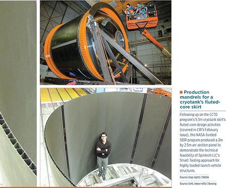
Production mandrels for a cryotank’s fluted-core skirt. Following up on the CCTD program’s 5.5m cryotank skirt’s fluted-core design activities (covered in CW’s February issue), this NASA-funded SBIR program produced a 2m by 2.5m arc section panel to demonstrate the technical feasibility of Spintech LLC’s Smart Tooling approach for highly loaded launch vehicle structures. Source (top right): NASA Source (left, lower left): Boeing
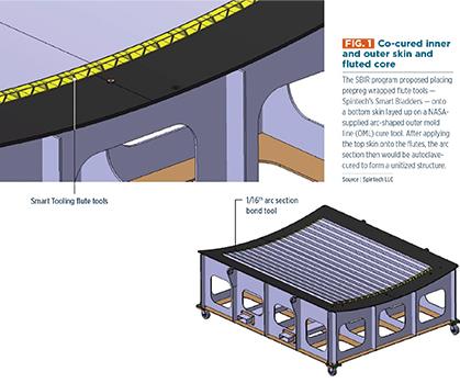
Fig. 1: Co-cured inner and outer skin and fluted core. The SBIR program proposed placing prepreg wrapped flute tools — Spintech’s Smart Bladders — onto a bottom skin layed up on a NASA- supplied arc-shaped outer mold line (OML) cure tool. After applying the top skin onto the flutes, the arc section then would be autoclave-cured to form a unitized structure. Source: Spintech LLC
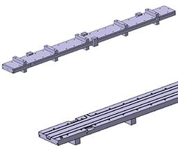
Step 1: The Smart Bladders must first be formed into their basic hollow configurations. This is done in a special mold depicted in the illustration. Proprietary reinforcement was layed onto a male mandrel, which is placed into the female clamshell mold. The shape memory polymer (SMP) resin was injected into the closed mold and cured to cast each Smart Bladder. Source: Spintech LLC
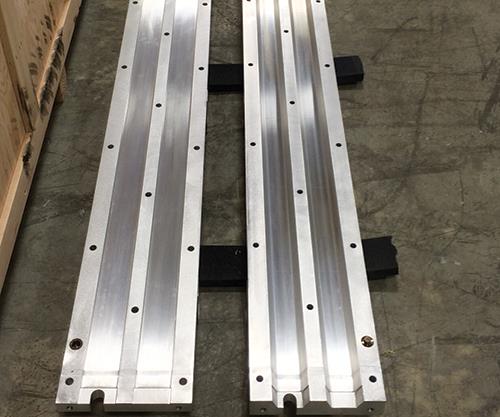
Step 2: The basic Smart Bladder blanks, however, then must be formed to final part tolerance. That is accomplished in this second metal mold set, which is machined to the flute inside mold line (IML) tolerances. There, the blank’s SMP material was conformed to the mold’s dimensions using pressurized air and heat — a shape it would hold once cooled again to room temperature. (This two-step forming process permits the use of a single mandrel and two-part female mold to form hollow bladders that then could be adapted to a variety of differently shaped parts.) This second mold would also be used to reset the Smart Bladders’ IML shape between part cure cycles, after the SMP material’s IML shape was “relaxed” to enable easy removal from the flutes. Source: Spintech LLC
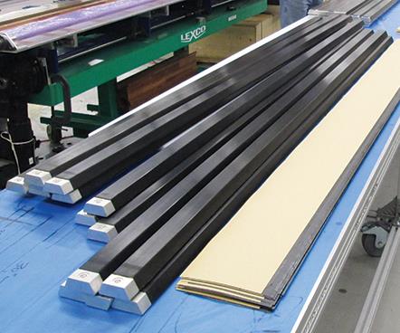
Step 3: The Smart Bladders, after removal from these second mold are shown here, shaped precisely to the flute’s IML and fitted with end caps. Source: Boeing
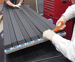
Step 4: Four plies of CYCOM5320-1 carbon fiber/epoxy prepreg were layed, each ply offset by 7.6 mm, to create a staggered joint in the final flute. These stepped plies were debulked into a stack called a charge. Source: Boeing
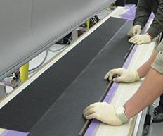
Step 5: Each carbon fiber prepreg charge (black line in center) was wrapped around a Smart Bladder (off-white line next to prepreg) and tamped down by an automated machine to create a pre-compacted flute preform. Source: Boeing
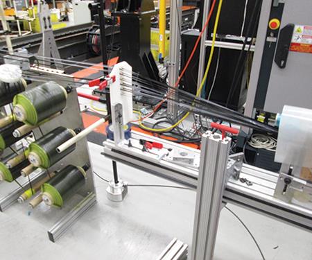
Step 6: To fill the small gaps between the slightly radiused top edges of the bladder supported layups between the flutes and the skirt’s top and bottom skins, pultruded radius fillers (or “noodles,”) were produced by pulling multiple slit tape carbon fiber tows through a heated die, where they were compacted and cured to the desired shape. Source: Boeing/Spintech LLC
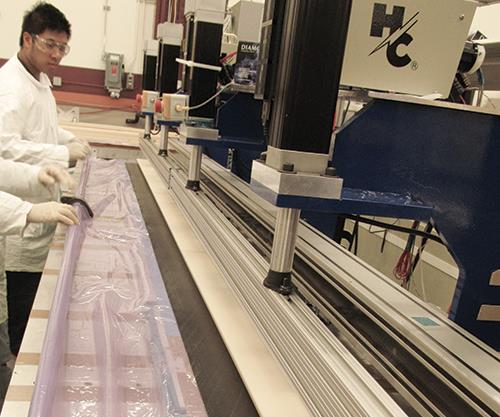
Step 7: Technicians collected the layed up smart bladders (alternating wide end in/ wide end out) in sets of eight or nine, debulked them under a vacuum bag to create a flute pack, then began laying in the radius fillers, as shown here. (This pack is shown from the end that clearly shows the perpendicular closure illustrated in Fig. 2) Source: Boeing
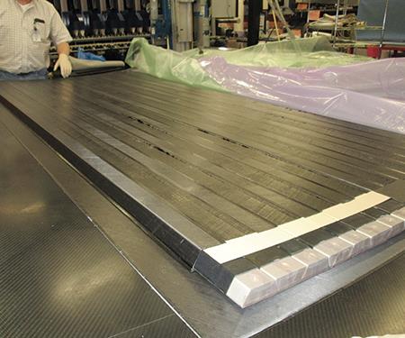
Step 8: A flute preform pack is shown here with all the pultruded radius fillers in place between them. This and the other fully kitted flutes were then debulked onto the arc section bottom/outer skin. Source: Boeing
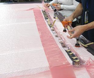
Step 9: After debulking, the top/inner skin was placed and debulked, and the whole assembly (shown here) was prepared for autoclave cure, with each Smart Bladder individually vented, via the end cap shown in Fig. 2, through the vacuum bag. Source: Boeing
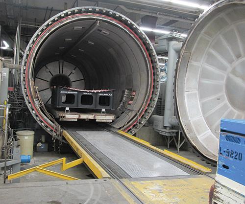
Step 10: The vacuum-bagged, fluted arc panel was then wheeled into this autoclave for cure at 121°C for 4 hours. Source: Boeing
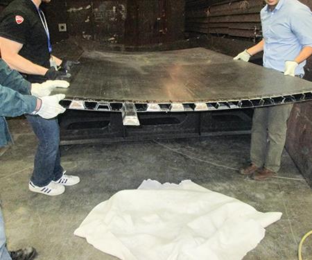
Step 11: After cure, the arc panel was heated above 62°C in a standard convection oven, enabling extraction of the softened Smart Bladders by hand. Source: Boeing
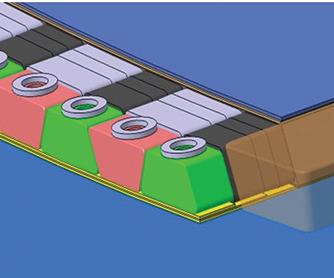
Fig. 2: More than a mere mandrel
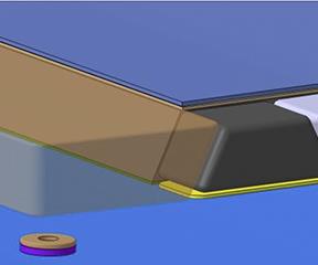
Fig. 2: Each Smart Bladder would be cast with a perpendicular closure on one end and after the casting mandrel was extracted, a metallic end cap would be bonded into the other end, to permit the hollow tool to be pressurized when it entered its elastomeric phase at high temperature while in the autoclave, to aid in compacting and consolidating the flute laminate from the inside while the vacuum bag compacted the layup from the outside. Source: Spintech LLC


In February, CW’s Focus on Design feature reported on the Composite Cryotank Technologies and Demonstration (CCTD) project’s successful build of a subscale 5.5m-diameter composite tank with special attention to the makeup of its carbon fiber-reinforced plastic (CFRP) fluted core skirt structure (Read more about it online “NASA/Boeing composite launch vehicle fuel tank scores firsts” under "Editor's Picks" at top right). Although the skirt’s all-new structural scheme was an unqualified improvement over previous honeycomb-cored sandwich skirt constructions, the CCTD team knew the rigid trapezoidal mandrels used to mold the skirt prototype’s core would not be practical for use in a production skirt for a tank that would fly on a launch vehicle.
In that scenario, explains Tom Margraf, the director of engineering for tooling technology innovator Spintech LLC (Xenia, OH, US), “the final cryotank skirt components will have to assemble to other pieces.” In order to accommodate them, the skirt’s flutes must taper at the structure’s open ends. “Each section’s flutes will have to narrow in cross-section to receive a coupling collar,” he explains. Thus narrowed during manufacture, then cured, the flute’s ends would prevent mandrel removal. As a next step, then, CCTD’s team of NASA and Boeing Co. (Chicago, IL, US) engineers worked with Spintech to demonstrate how the latter’s Smart Tooling products could provide a solution to this problem.


NASA funded a Small Business Innovative Research (SBIR) program, using CCTD’s 5.5m skirt design as a baseline geometry, with two main objectives: Demonstrate the technical feasibility of a Smart Tooling product on a NASA launch vehicle component, and evaluate the performance of Smart Tooling in comparison to the component’s baseline tooling methodology. To secure those objectives, Spintech made 27 3m-long mandrels, trapezoidal in cross-section, called Smart Bladders, which Boeing then used to mold a 2m-by-2.5m fluted-core skirt/cryotank arc-section panel.
Requirements for fluted core tooling
The fluted-core construction used in the CCTD project was created by wrapping four-ply stacks of prepreg around long, thin mandrels with trapezoidal cross sections, arranging these layups on a faceskin layup, topping them with another faceskin layup and then curing the result as a unitized skin/fluted-core structure in an autoclave. The wrapped trapezoidal tools were alternated — wide end facing out/wide end facing in — to achieve the nesting that creates the truss-like core structures.
Production-worthy mandrels would need to be stiff enough at room temperature, during and after layup, to allow hand carry without flexing significantly, which could induce wrinkles. They also would have to have sufficient compressive strength to resist automated flute-wrapping techniques and, eventually, automated fiber placement (AFP) head pressure, yet be highly elastic during cure to translate sufficient internal force from the autoclave onto the wrapped layup radii, webs and caps. This would ensure full compaction with minimal voids. Further, the tooling had to yield a part with consistent web, skin and radius dimensions — the flute walls and skins could not bulge (exhibit concavity/convexity).
After cure, the mandrels had to release from the flute inner walls and then be pulled or pushed out of the cavity with minimal force. Further, the mandrel materials had to withstand multiple cure cycles with limited refurbishment, and tool cost must be reason- able vs. other tooling approaches. Finally, the mandrels had to be scalable from the 3m lengths that would be used in this SBIR skirt arc test section to the roughly 30m lengths envisioned for next- generation launch vehicle cryotank skirt structures.
Dynamic modulus polymer tooling
Spintech’s patented Smart Tooling products are based on a class of thermoset materials called shape memory polymers (SMP). These are dynamic-modulus materials that respond to temperature. For example, an epoxy-based SMP can exhibit properties similar to common epoxy resins up to 80°C, but then transition from a rigid to an elastic material in the 80-105°C range, and become fully elastomeric above 105°C, achieving strains up to 400% (neat polymer).
Smart Tooling replaces the metal mandrel with the Smart Bladder, a hollow SMP tube that is pre-formed to the part’s inner trapezoidal mold line. The Smart Bladder is rigid at room temperature, but becomes a balloon-like elastomer during cure, capable of translating internal cavity pressure from either the autoclave or a separate pressure system (e.g., a compressor or gas bottle) — and can withstand up to 191°C. Thus, Smart Bladders act as a rigid layup mandrel at room temperature, but can function at elevated temperatures as a bladder to consolidate the laminate from the inside out and to facilitate removal.
“This technology originated from an SBIR targeting the F-35 composite inlet duct, which required very tight control of the inner mold line,” recalls Margraf. “The Smart Tooling material’s ability to transition from rigid during lay-up to elastomeric during cure, and consolidate against an outer mold line rigid tool surface, found strong market acceptance in components that were traditionally bladder molded, like blade spars,” he adds.
Margraf explains that the typical solution for this type of problem is to lay up the part onto a multi-piece metal mandrel and place that inside a two-piece, machined female cavity mold. “Now you must go in and disassemble the metal layup mandrel and replace that with a vacuum bag so that you can achieve compaction on the interior surface,” he adds, because the metal mandrel will act as a heat sink and could cause thermal non-uniformities that reduce residual stress within the part. “Not only is this labor-intensive, it also risks damage to the layup during removal of the steel mandrel and insertion of the vacuum bag.”
“The Smart Bladder is a layup tool that does not have to be removed prior to autoclave cure, but instead exerts compaction pressure on the part like a vacuum bag does,” says Margraf. “Because we relax the Smart Bladder for easy extraction after cure, we then reform it between cycles to the net inner mold line of the part, using a reasonably priced metal mold.”
Margraf notes that Smart Tooling excels with parts that have line-of-sight issues for extraction, meaning they are curved so that you cannot pull a metal mandrel out without disassembling it. “Our material is elastomeric, so you are essentially pulling out a rubber hose which has no clearance issues with the part.”
Demonstrating fluted core production
Boeing provided the flute design for the 5.5m cryotank and NASA Marshall Space Flight Center (Huntsville, AL, US) supplied the composite outer mold line (OML) cure mold for the tank arc section (see Fig. 1). Spintech then began manufacture of the Smart Bladders, one at a time, with a single set of matched steel clamshell molds (see Step 1). Proprietary reinforcement, which increases Smart Tool toughness but still allows for elastomeric expansion, was placed onto a male mandrel, which was then placed into a female clamshell mold. The clamshell mold was closed and SMP resin was injected and cured to cast a simple, hollow “blank” for each Smart Bladder. The final shape for each Smart Bladder would be imparted later.
In order to create a sealed cavity, each Smart Bladder blank was cast with a perpendicular closure on one end, and a metallic end cap was bonded into the other end after the metal mandrel for casting was extracted (see Fig. 2). The end caps will permit pressurization of the Smart Bladder in its heat-induced elastomeric state during the cure cycle.
Each Smart Bladder blank was then placed into a second metal mold, machined to the net inner mold line (IML) tolerance of the flutes (Step 2). For this demonstration project, the second mold may have seemed unnecessary, but Boeing wanted to adhere to the actual production process. When used to produce a part with convex-to-concave cross-section changes or other line of sight issues, the simply shaped hollow Smart Bladder is placed inside the second mold and conformed using compressed air. Boeing used this process in the SBIR program, heat-forming each Smart Bladder to its final shape. This same forming mold was also used after each cure cycle to reset the IML flute tolerances of the Smart Bladders, ensuring proper layup geometry for subsequent parts.
Plies of CYCOM 5320-1 carbon fiber/epoxy prepreg from Cytec Solvay Group (Woodland Park, NJ, US) were cut with a 3-axis automated cutter and kitted. Four plies were then layed, each ply offset by 7.6-mm, to create a staggered joint in the final flute. These stepped plies were debulked into a stack called a charge (Step 3). Each charge was dropped into an automated machine and a Smart Bladder was placed on top. The machine then pushed the Smart Bladder and prepreg plies down into a female cavity. The wings of the prepreg (sized larger than the cavity) then stood up, extending beyond the tool cavity. The machine then lowered arms that folded these wings back onto the top side of the bladder, forming a flute. The machine then tamped down the completed layup, which resulted in a compacted flute preform (Step 4). Thus, the charge was wrapped very tightly around the Smart Bladder, and the stepped plies created the staggered joint that is preferred over a butt joint for load transfer. Sets of eight or nine flutes were then collected and debulked under a vacuum bag to create a flute pack (Step 5).
The debulked flute packs were then placed onto the bottom/outer skin layup, which already had been applied to the carbon composite arc section mold tool and debulked. Pultruded carbon fiber composite “noodles” were required to fill in gaps between the flutes. Multiple s lit tape carbon fiber tows were pulled through a heated die and compacted into the required shape (Step 6). Once the radius fillers were placed between all of the flutes (Step 7), the top/inner skin was applied on top of the now smooth surface and debulked to compact it to the flute-radius filler assembly. The layup was then prepared with thermocouples and vacuum bag for autoclave cure (Step 8). Each Smart Bladder’s end cap was individually vented through the vacuum bag to the autoclave atmosphere, which prevented them from crushing under the autoclave cure pressure (6 bar) and allowed for pressurization and compaction of the flute interiors (Step 9).
The arc panel was step-cured at 121°C for four hours under full vacuum (Step 10). After initial cure, the panel was heated above 62°C in a standard convection oven so that the mandrels were sufficiently flexible for extraction. The panel was removed from the oven and the bladders were extracted by hand (Step 11). After the Smart Bladders were extracted, a final free-standing post-cure at 177°C was conducted on the panel. Although a stepped cure process was used here, per NASA material and process specifications, Smart Bladders do not require a step-cure process and are compatible with cures up to 191°C.
Extending to fastener-free and low-volume primary structures
Boeing completed production of the arc panel in April 2015 and reported that the Spintech have since completed more complex skirt flute geometries, including unitized skin-flute structures with significant change in cross-section. “We are ... demonstrating [its] compatibility with more complex flute designs that will provide a solution for trapped tooling with no line of sight for removal,” he says.
Margraf notes that the fluted panels look a lot like unitized control-surface parts (skins with integrated omega stringers) that Spintech is also heavily supporting right now. “We can co-cure all of these layups together in a single cycle because we are able to exert consolidation pressure on all composite surfaces, whereas the baseline process can only exert pressure in one direction,” he explains. “So now you can, theoretically, get rid of chicken rivets.” Margraf cites Spirit AeroSystems’ (Wichita, KS, US) Inflexion technology as an example, developed to produce fully integrated composite fuselage modules (Read more online about Spirit AeroSystems’ Inflexion technology in “Inflexion technology enables complex composite structures without fasteners” under "Editor's Picks" at top right).
“That is one of the end games for our products,” he points out. “We can deliver solutions for manufacturing fully unitized structures that do not require any secondary bonding or fastening.”
Spintech is working with a variety of partners to push this technology, and has already deployed unitized-structure tooling solutions in markets with less onerous certification requirements. “One of our customers told us their manufacturing process, including trimming, assembly, bonding and fastening, used to take a month per part,” says Margraf, but he claims, “They can now do it as a single cured part in a week.”
Having attained a manufacturing readiness level (MRL) of 10 and technology readiness level (TRL) of 9 via previous programs and the successful demonstration in the Boeing/NASA fluted core SBIR program, Smart Bladders are now validated as a solution for volume production. Innovative technologies like these offer a welcome solution to an industry that needs to relentlessly pursue reductions in manufacturing cost and time that do not sacrifice quality in primary composite structures.


Related Content

Carbon fiber composite pallet revolutionizes freight industry
LOG Point Pallet fuses advanced materials with innovative design and manufacturing to improve supply chains worldwide.
Read More
Sulapac introduces Sulapac Flow 1.7 to replace PLA, ABS and PP in FDM, FGF
Available as filament and granules for extrusion, new wood composite matches properties yet is compostable, eliminates microplastics and reduces carbon footprint.
Read More
The potential for thermoplastic composite nacelles
Collins Aerospace draws on global team, decades of experience to demonstrate large, curved AFP and welded structures for the next generation of aircraft.
Read More
Low-cost, efficient CFRP anisogrid lattice structures
CIRA uses patented parallel winding, dry fiber, silicone tooling and resin infusion to cut labor for lightweight, heavily loaded space applications.
Read MoreRead Next

Inflexion technology: complex composites without fasteners
Spirit AeroSystems has developed production methods using rigid-flexible tooling for more affordable unitized composite aerostructures.
Read More
NASA/Boeing composite launch vehicle fuel tank scores firsts
Subscale 5.5m-diameter cryogenic tank demonstrator with innovative fluted-core skirt is formed via robotic AFP and cured out of the autoclave.
Read More
Ceramic matrix composites: Faster, cheaper, higher temperature
New players proliferate, increasing CMC materials and manufacturing capacity, novel processes and automation to meet demand for higher part volumes and performance.
Read More