
Shear testing of high-shear strength composite laminates
CW columnist Dan Adams compares three V-notched shear test configurations used to measure the shear stiffness and shear strength of composite materials.

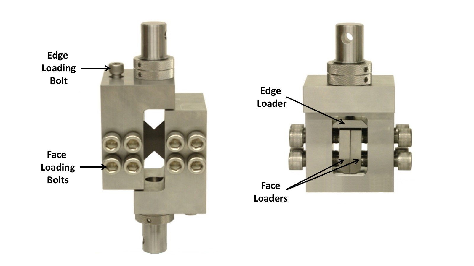
Fig. 1a: Combined loading shear test fixture.
Source (all images) | Dan Adams
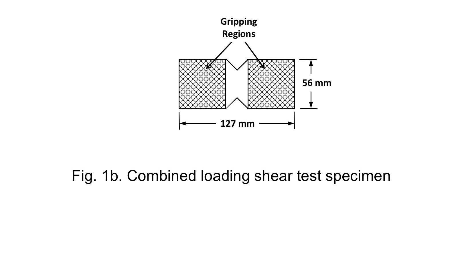
Fig. 1b: Combined loading shear test specimen.
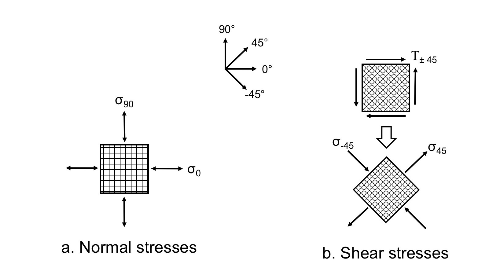
Fig 2: Efficient fiber orientations for stresses
a: Normal stresses
b: Shear stresses
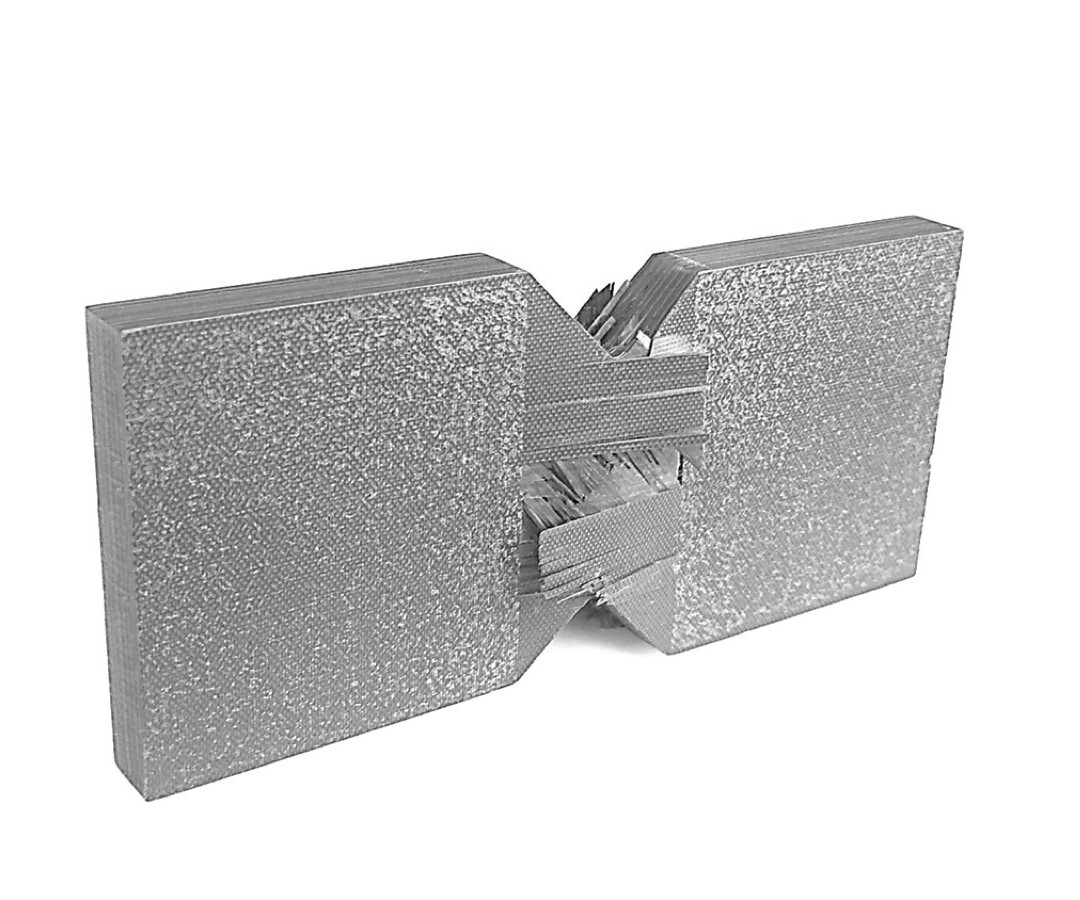
Fig 3: Failure mode in quasi-isotropic shear specimen.
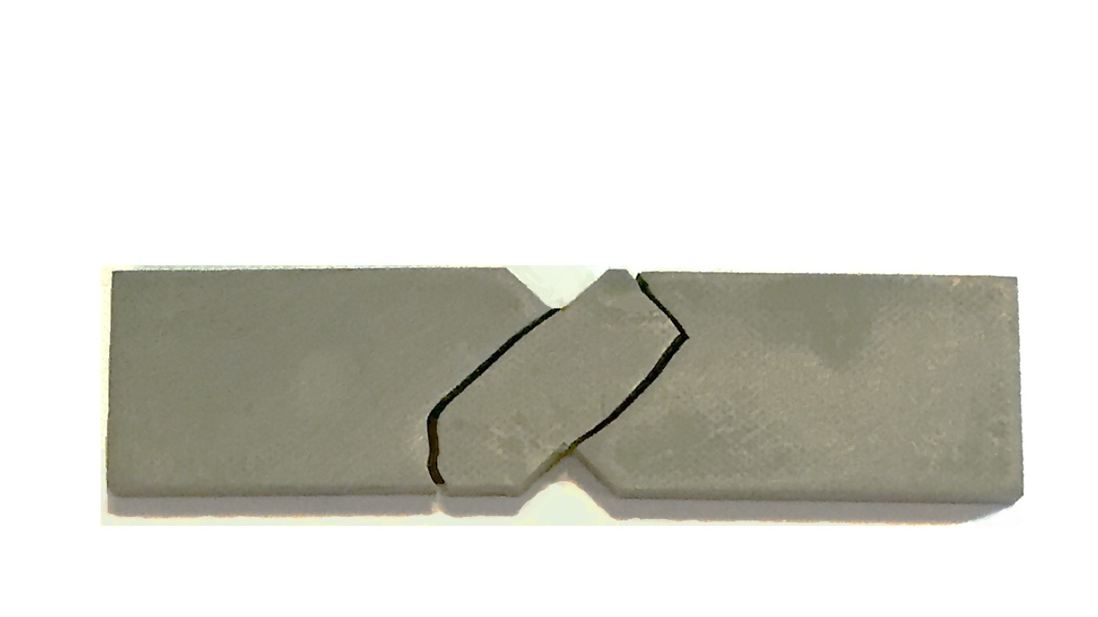
Fig 4: Failure along 45° planes in epoxy shear specimen.
Share


In my October 2015 column, I compared three V-notched shear test configurations used to measure the shear stiffness and shear strength of composite materials: The V-notched beam shear test (ASTM D53791), the V-notched rail shear test (ASTM D70782) and the V-notched combined loading shear test. All three use specimens with 90° V-notches machined into the central test section to produce a region of uniform shear stress.
The primary differences between the three shear test configurations are the size and shape of the test specimen as well as the methods of load application: through the top and bottom specimen edges (ASTM D5379), through the specimen faces (ASTM D7078) or both (combined loading shear test). Here, we’ll focus on shear testing of thick, high-shear-strength laminates for which the combined loading shear test method is best suited.


The combined loading shear test fixture (Fig. 1a) is similar to that used in the V-notched rail shear test, but is larger and has bolt-adjustable specimen edge loaders. The specimen is loaded into one fixture half, using an alignment jig to properly position it. The edge loader bolt is tightened to ensure specimen edges are in contact with the fixture. Next, the bolts for the face loaders are adjusted to align the specimen’s centerline with the centerline of the fixture half before tightening. The second fixture half is mounted in the same way onto the specimen’s other end. Finally, the edge loader bolts for both fixture halves are loosened, then retightened to ensure that no preload is applied to the specimen edges. The assembled fixture is mounted into a universal testing machine via pinned adapters and loaded in tension.
Although the central V-notched region of the combined loading shear specimen has the same geometry as in the V-notched rail shear test, the gripping region’s length is increased from 25 to 51 mm, providing twice the area for both edge and face loading. The resulting 127-mm-long by 56-mm-wide specimen (Fig. 1b) has been shown to produce acceptable gage-section failures in relatively thick, high-shear strength laminates that require applied shear loads up to 100 kN3.
High-shear strength composite laminates are of interest for many structural applications, including the central web region of composite beams, which carry the majority of the shear stress under transverse loading. Unlike tension and compression stresses, which are carried most efficiently by reinforcing fibers oriented in the direction of the stress (Fig. 2a), shear stresses are carried most efficiently when fibers are oriented at ±45° angles (Fig 2b). This concept can be visualized by considering the shear stress element rotated 45°, showing that the ±45° fibers are actually carrying the stresses directly in tension and compression. For this reason, high-shear-strength composite laminates typically have a relatively high percentage of ±45° plies. Note that a quasi-isotropic [0/±45/90]s laminate is expected to have relatively high shear strength, having 50% of its plies in ±45° orientations.
The ability to mechanically test high-shear-strength laminates is especially important because of the challenges associated with predicting their shear strength. Using laminated plate theory analyses with progressive ply failure4, shear-loaded multidirectional laminates typically are predicted to experience matrix-dominated ply-level damage prior to reaching their ultimate shear strength. Additionally, predicted shear strengths are highly dependent on the ply failure theory used.
As an example, combined loading shear testing and laminated plate theory strength analyses were performed using a [0/±45/90]4S quasi-isotropic carbon fiber/epoxy laminate. The laminate shear strength was predicted using three ply-failure theories: maximum strain, Tsai-Wu and Hashin. Ply damage produced during incremental shear loading was modeled by reducing associated stiffness properties of the damaged ply4. The three failure theories predicted ply-level damage initiating at applied shear stress levels of 250-443 MPa. The ultimate shear strength measured from shear testing was 346 MPa3, whereas the predicted strengths were 250-564 MPa.
The post-failure condition of the quasi-isotropic shear specimens (Fig. 3) showed a complex failure mode, with different failure planes produced in the various ply orientations. Knowing that the maximum shear stress is produced on the vertical plane connecting the V-notches, it is logical to expect that a proper shear failure would occur on this vertical plane. However, shear loading of a multidirectional laminate produces a complex, multiaxial stress state that is different for each ply orientation. Thus, the rather complex failure mode observed in the quasi-isotropic shear specimen is less surprising.
Interestingly, isotropic materials also can provide somewhat unexpected failures under shear loading. For example, Fig. 4 shows the post-test condition of a V-notched epoxy shear specimen. The specimen failed along 45° planes, which, as shown previously (Fig. 2b), is the plane on which the maximum tensile stress occurs. Thus, even some isotropic materials do not fail on the plane of maximum shear stress when subjected to shear loading.
References
1ASTM D5379/D5379M-12, “Standard Test Method for Shear Properties of Composite Materials by the V-Notched Beam Method,” ASTM International (W. Conshohocken, PA, US), 2012 (first issued in 1993).
2ASTM D7078/D7078M-12, “Standard Test Method for Shear Properties of Composite Materials by the V-Notched Rail Shear Method,” ASTM International (W. Conshohocken, PA, US), 2012 (first issued in 2005).
3Litz, D. J. “Development of the Combined Loading Shear Test Method and Shear Strain Measurement in the V-notched Rail Shear Test,” M.S. Thesis, Department. of Mechanical Engineering, University of Utah, 2012.
4Gibson, R. F. “Principles of Composite Material Mechanics,” 4th Edition, CRC Press, 2016.
About the Author
Dr. Daniel O. Adams is a professor of mechanical engineering and has been the director for 21 years of the Composite Mechanics Laboratory at the University of Utah and vice president of Wyoming Test Fixtures Inc. (Salt Lake City, UT, US). He holds a BS in mechanical engineering and an MS and Ph.D in engineering mechanics. Adams has a combined 38 years of academic/industry experience in the composite materials field. He has published more than 120 technical papers, is vice-chair of ASTM Committee D30 on Composite Materials and co-chair of the Testing Committee for the Composite Materials Handbook (CMH-17). He regularly provides testing seminars and consulting services to the composites industry.


Related Content

Automated robotic NDT enhances capabilities for composites
Kineco Kaman Composites India uses a bespoke Fill Accubot ultrasonic testing system to boost inspection efficiency and productivity.
Read More
Laser-excited acoustics provide contact-free, nondestructive composites inspection
Xarion’s couplant-free NDT technology uses laser physics and a membrane-free optical microphone, eliminating the requirement for fluid coupling, widening the scope for NDT technology.
Read More
Putting next-generation composite materials, processes to the test
Research at Faserinstitut Bremen’s ECOMAT site, alongside industry partners, aims to enable sustainable, aerospace-focused composites — including thermoplastic welding and cryogenic material testing.
Read More
Modular approach to material card development of composites
Forward Engineering GmbH walks through a modular testing and simulation approach for automotive/aviation composites enabling more accurate material selection earlier in the design phase.
Read MoreRead Next

Kaneka BMI material attains >25% lead time, >20% tool cost reductions in Janicki evaluations
Process evaluations find that novel BMI polymer chemistry addresses longstanding manufacturing challenges of BMI tooling prepregs while maintaining high temperature performance and durability.
Read More
Bonded fastening meets the digital factory
Automation and XR tools aim to scale adhesive fastening for composites at next-gen aerospace production rates.
Read More
Post Cure: CFRP mainframe, modern manufacturing techniques pioneer next-generation rigid airships
Advanced composites enable the revival of rigid airships in LTA Research's 400-foot-long Pathfinder 1.
Read More