


The ARE comprises a new, shorter configuration with a forward-swept horizontal tail plane (HTP), offering weight savings and laminar flow aerodynamics for fuel savings. Photo credit, all images: Airbus, Aernnova, Clean Sky 2/Clean Aviation
The Advanced Rear End (ARE) demonstrator was one of the work packages in the 2015 Clean Sky 2 technical program, aimed to develop an all-carbon fiber-reinforced polymer (CFRP) rear fuselage to provide significant weight savings for next-generation short- and medium-range large passenger aircraft (LPA).
Originally conceived to help enable a rear fuselage-mounted Open Rotor engine — targeting significant reductions in weight, noise and CO2 emissions — the ARE was reconfigured in 2017 to enable a radical new aerodynamic design that could be matched with a range of propulsion systems, including electric. The goal of an all-CFRP structure remained, but the new forward-swept horizontal tail plane (HTP) design shortened the fuselage section, requiring a new rear fuselage design and aerodynamics analysis, as well as a new systems layout.


“There are two main streams to this Clean Sky 2 project: The first is the technical dossier and the second is the full-scale demonstrator that we will finish building this year,” explains Pierre Durel, project officer for the Clean Aviation Joint Undertaking (CAJU), which was launched in November 2021 to carry forward from Clean Sky 2.
“The first [technical dossier] is more of a virtual stream,” notes Enrique Guinaldo, head of airframe engineering empennage R&T for Airbus (Getafe, Spain) and ARE demonstrator project leader, “where we analyze aerodynamics, manufacturing constraints and how this new configuration will fit into the overall systems design and airframe design. The second stream is more physical, where we have two relevant demonstrators: an upper shell, which is a portion of the full-scale rear fuselage but without the lower shell, and then a lateral panel, which represents one-third of the lower shell.”
These two demonstrators have been structured to explore a number of different technologies and address the key challenges in the new ARE configuration. The lateral panel is being manufactured by the German Aerospace Center (DLR, Stade) with tooling developed in the FRAMES subproject, using automated fiber placement (AFP) with heat from a xenon flash lamp instead of a laser (see “Clean Sky 2 FRAMES project advances heating simulation of thermoplastic composite AFP with xenon flashlamp”). Meanwhile, the upper shell demonstrator, managed by Tier 1 supplier Aernnova (Miñano, Spain), will not include the HTP, vertical tail plane (VTP) or lower fuselage, explains Durel, “but just the upper fuselage skin with integrated stiffeners and one fitting for attaching the VTP. This fitting has been redesigned from aluminum to a complex 3D composite part.”
New design, new composite frames
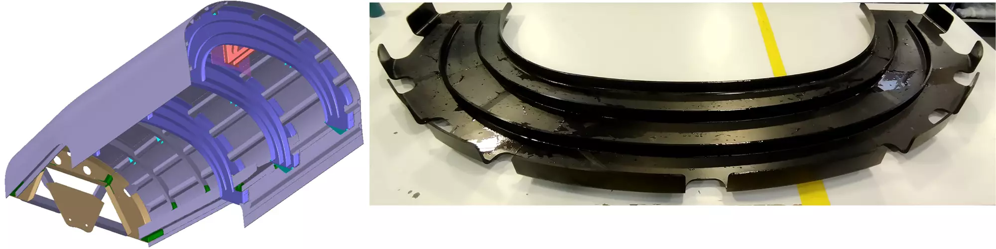
The new design validated in the ARE demonstrator requires three multi-flange composite frames — shown in rendering (top) and actual RTM part (bottom) that can transfer loads from the VTP to the fuselage, historically handled by forged and machined aluminum frames. Photo Credit: Airbus, Aernnova, Clean Sky 2/Clean Aviation
Guinaldo explains that the upper shell is the most complex part of this new rear fuselage configuration, which is why it was chosen as the industrial demonstrator. “The rest of the section is a mix of thermoset and thermoplastic composites technologies,” he says. “The skins and stringers are prepreg and the highly loaded frames are made using a resin transfer molding [RTM] process. We have tried to explore which technology was the best fit for each application.”
ARE is one of five large Clean Sky 2 demonstrators designed to advance Innovative Structures and Production Systems and organized within the LPA Innovative Aircraft Demonstrator Platform (IADP). It passed technology readiness level (TRL) 3 in February 2021, thereby freezing the design, and completed component parts production in 2021. These will be assembled in 2022 and all testing is to be completed by the project’s end in 2023.
The ARE’s overall goals include a 20% savings in cost and weight versus a conventional single-aisle aircraft design. But to achieve this, many innovations must be combined to work together, says Guinaldo. “This includes new tooling and a new, highly loaded composite frames design, as well as simulation, mechanical testing and materials studies, all to enable this radical new rear fuselage and empennage configuration.”
Multiple partners, radical reconfiguration
ARE has involved more than 10 subprojects, including Airbus-led TAILSURF, IMPACT and MONNALISA to optimize rear fuselage and empennage shape, to validate aerodynamics and aeroelastic lift-enhancing devices and to study deicing technologies; Airbus-led CHRZASZCZ to optimize auxiliary power unit (APU) air intake and muffler systems; HEGEL, led by Fraunhofer Gesellschaft (FHG, Munich, Germany) to complete fatigue analysis; and FALCON, led by Aernnova to develop low-cost, smart tooling for the highly loaded, RTM’d composite frames, as well as INNOTOOL to develop assembly tooling for the ARE upper shell demonstrator and the press-forming tool used to produce the thermoplastic composite ARE closing frame. In CERES and TABASCO, Airbus leads the ARE test program, which includes the Aernnova highly loaded RTM frames.
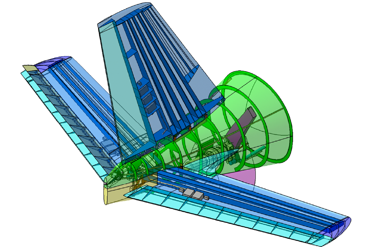
One of the key aspects that make the new ARE design radical is its forward-swept HTP. Angled opposite of a conventional rear fuselage, the goal of the design is to improve laminar flow at the tail, which reduces aerodynamic drag and fuel burn. It also shortens the rear fuselage, saving weight and creating potential space for an extended passenger cabin (or hydrogen fuel storage).
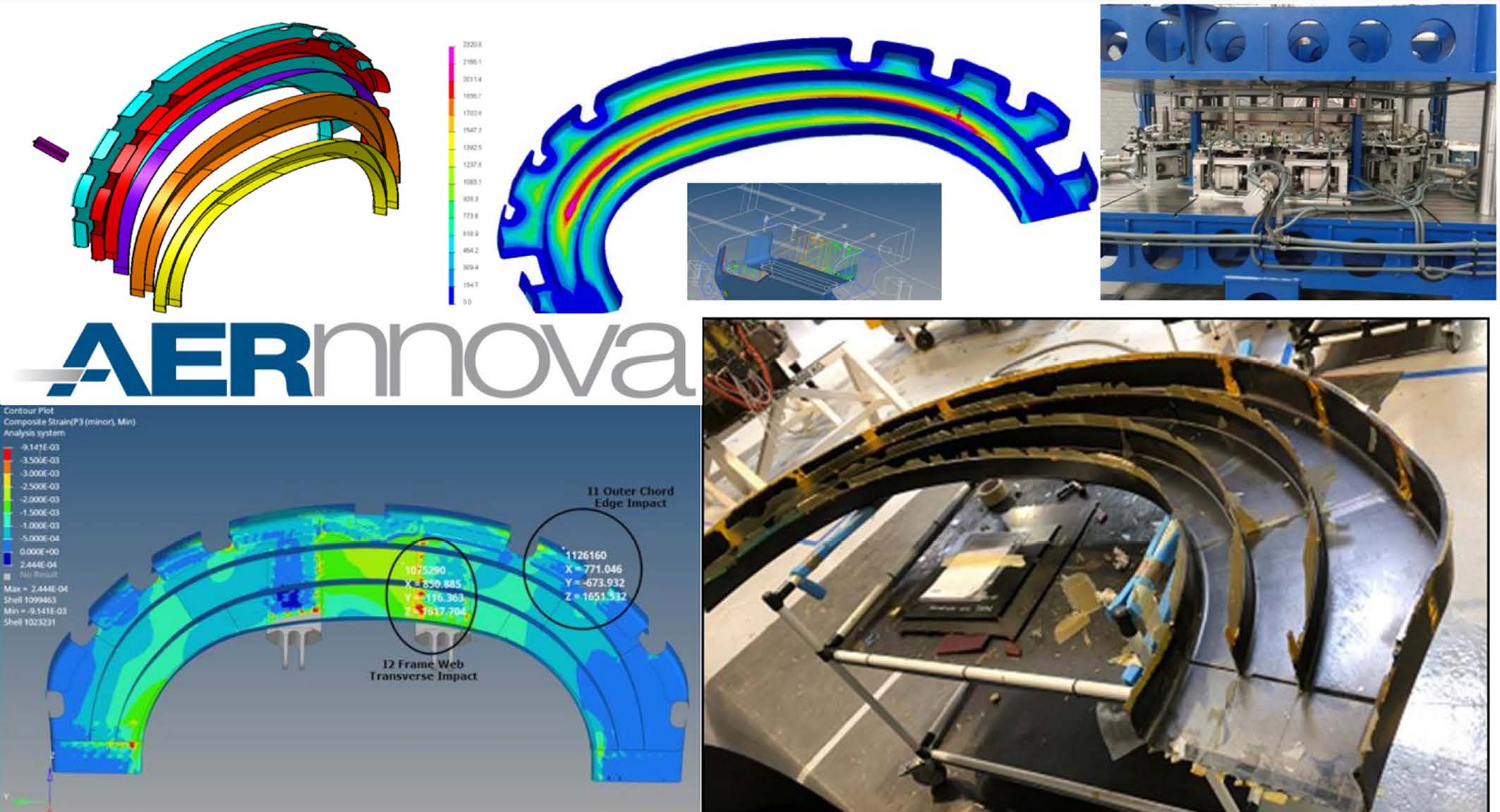
However, this shortened end section also pushes the APU forward to sit beneath the VTP. “This requires addressing the risk that the APU would catch fire or have a rotor failure, sending fragments with high energy toward the interface with the VTP,” says Guinaldo. “Our response was to design a composite containment box surrounding the APU to protect critical areas of the airframe.” Partners DLR and the French Aerospace Lab Onera (Palaiseau) tested a variety of materials — braided reinforcements, carbon fibers, high-density polyethylene fibers, thermoplastic prepreg and also different thicknesses and layups. “We ran a full ballistic impact test campaign, both physical testing and virtual simulations, to understand the behavior. We correlated our physical test results to improve the simulation methodology. Through this work, Onera and DLR were able to define the geometry and detail a solution for this containment structure.” This box will also include a firewall. “The full development of this firewall is outside the scope of this project, but is not seen as a technical challenge, and will most likely use fire protection materials similar to what we use today.”
Highly loaded, multi-flange frames
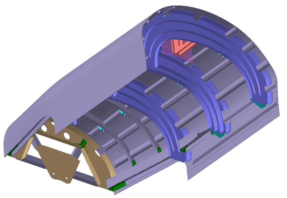
Most CW readers have seen CFRP fuselage frames, those curved parts with angled “feet” that attach to the fuselage skin and feature “mouseholes” where the fuselage’s longitudinal stringers fit through. “These are what we call shape frames,” says Guinaldo. “They basically maintain the pressurized fuselage shape but they are not intended to transfer interface loads. The frames we have developed for the ARE must transfer the interface loads from the VTP to the fuselage, which creates a very highly loaded local area. Until now, this loading has been handled by complex forged and machined metallic frames. But these are expensive and weigh a lot. They also have a different CTE [coefficient of thermal expansion] than the surrounding composite structure, which, under thermal loads, can add stresses between the frames and skin for the rest of the fuselage.”
Highly loaded interface frame
The RTM frame shown here uses increased thickness and multiple flanges across its web to handle high local loads in the VTP area of the ARE demonstrator compared to shape frames used in today’s state-of-the-art composite fuselages. Photo Credit: Airbus, Aernnova, Clean Sky 2/Clean Aviation and Aitiip
“Switching these interface frames to composites is definitely a step beyond,” he continues. “This is the first time we are introducing such high loads into a composite frame component.” To do this, a new design was developed and patented by Aernnova. It uses several flanges within the frame to provide the stiffness and strength needed. And, he notes, “the radius of curvature in these rear fuselage frames is small. This, combined with the 7-8 millimeters in thickness required to carry the load, made the composite frame manufacturing even more complex.”
Preforming multiple flanges
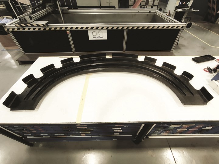
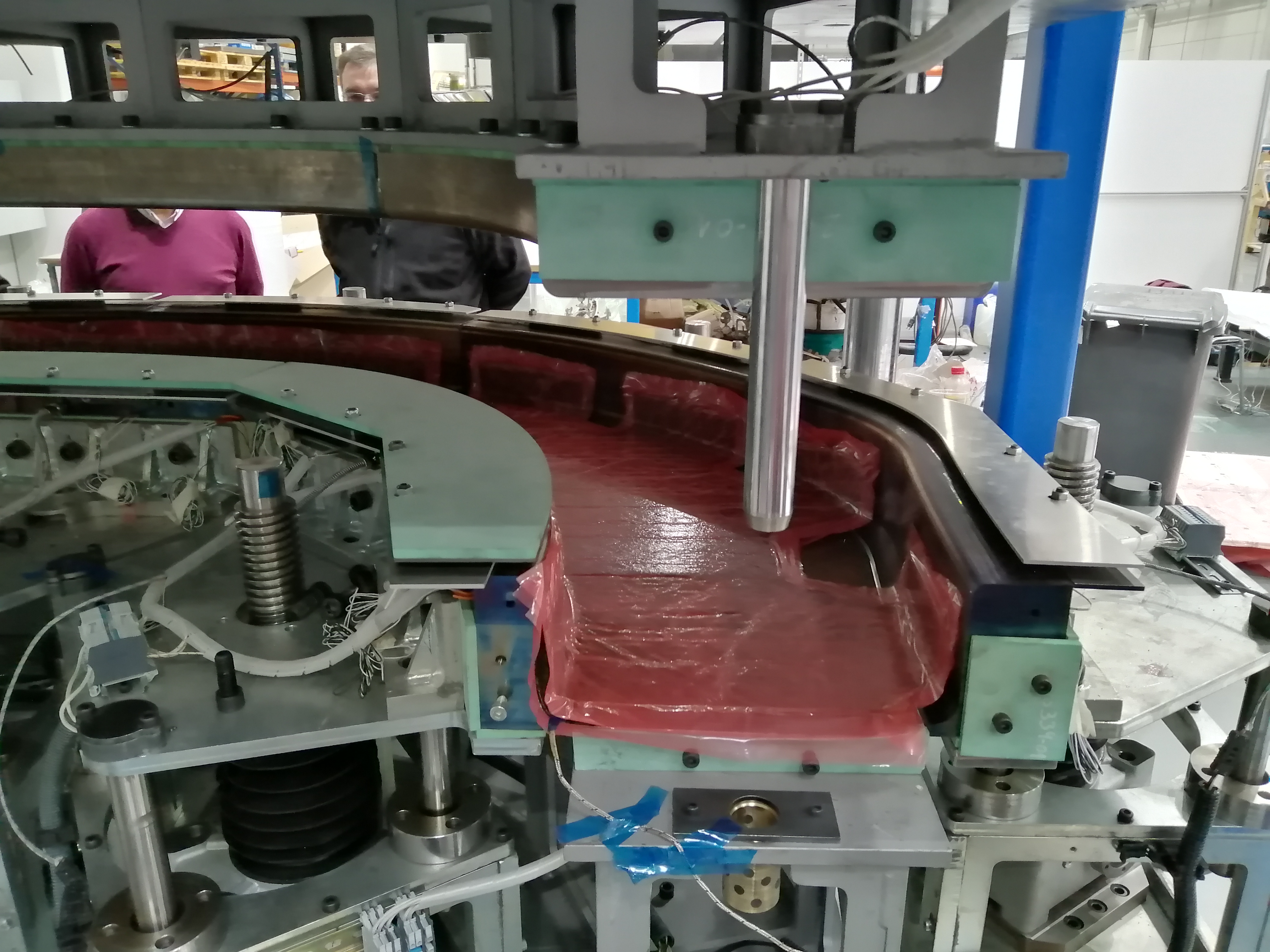
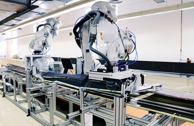
Preforming for the interface frames uses a tool developed by Aitiip in the FALCON subproject and a flexible process to press-form HiTape UD dry fiber layups, acquiring and analyzing data during preforming to correct actuation of the press and tool, if needed, to prevent defects. Photo Credit: Airbus, Aernnova, Clean Sky 2/Clean Aviation and Aitiip
“We use a press for hot-forming the flat C shape and also the C-shaped flanges,” says Luis Aliaga, executive project manager at Aernnova. “The tight curvature can create wrinkles when the reinforcement materials are bent. We tested many different materials.” The final choice was HiTape dry unidirectional (UD) tape and RTM6 epoxy resin, both from Hexcel (Stamford, Conn., U.S.).
Aernnova worked with FIDAMC (the Composites Research, Development and Application Centre, Madrid, Spain), which developed the AFP flat layups using HiTape and supported the automatic forming cycle in the FALCON subproject (see discussion below). This forming achieved the C shape of the multi-flange frames and enables industrialization for high production rates.
“We completed coupon and element level mechanical tests and many simulations in order to predict the behavior of this material in the final part,” notes Aliaga. “We also completed many simulations of the resin injection to confirm an injection strategy.” The final one-shot process used multiple injection points to ensure proper resin wetout of the complex-shaped preform.
But why was RTM chosen over thermoplastic composites, which offer increased toughness and heat resistance? “The thermoplastic technology was not mature enough to develop the highly loaded interface frames,” says Aliaga. “But the closing frame of the rear fuselage is going to be thermoplastic.” He notes that by the end of the project, ARE itself will reach TRL 6 but the closing frame — to be made from Toray Advanced Composites (Nijverdal, Netherlands) LMPAEK material — will only reach TRL 4. “We are not yet there with the thermoplastic processes that would be required for these interface frames,” says Aliaga.
FALCON tooling for frames
In the FALCON project, Aitiip Centro Tecnológico (Zaragoza, Spain) developed a unique, 150-ton-capable steel press tool for preforming the frame web and flanges. The company also built an RTM curing tool. These tools were designed to be versatile, able to produce CFRP frames for different fuselage sections subjected to different loading levels. The aim was also to reduce tooling cost by 40%, production time by 30% and production cost and energy by 20% each. To achieve this, FALCON also innovated use of software, control, monitoring and modularity.
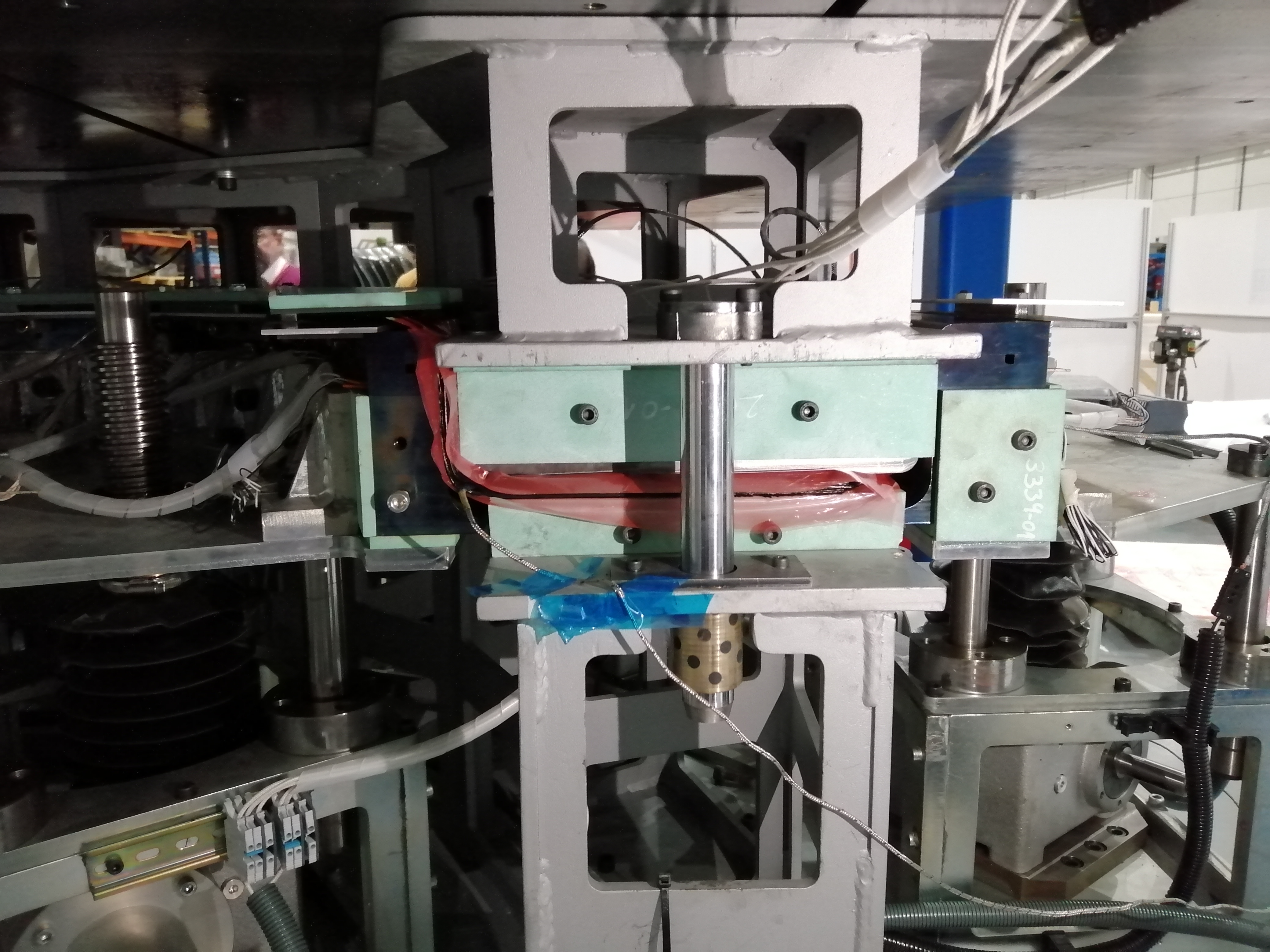
Actuated tool for preforming
In the FALCON subproject, Aitiip developed a unique, servo-motor actuated 150-ton capable press tool for preforming multiple sizes of CFRP frame components for different fuselage sections. Photo Credit: Airbus, Aernnova, Clean Sky 2/Clean Aviation and Aitiip
Both the preforming and RTM tools used multiple mandrels. The preform tool can shape the flat C-shape web for the highly loaded frames as well as the smaller C flanges. Its mandrels help shape the fabric and prevent wrinkles. Aitiip developed a unique servo-motor concept to enable flexible press-forming for U-, T- and Z-shaped stringers from any kind of prepreg fabric or UD tape. This servo-forming concept acquires and analyzes data during preforming to correct actuation of the tool and press if needed. The steel preform tool conducts heat from the forming press with cooling aided by forced air, both adapted to part geometries via embedded channels in the tooling.
The frame preforms are subsequently placed into the RTM curing tool, which comprises upper and lower molds, plus mandrels to maintain each preform’s position during injection and cure. Both preforming and RTM are monitored and controlled in real time using a closed loop control system, avoiding errors in the dimensional and thermal aspects of production. Together, with the one-shot RTM approach, this achieves energy and material savings.
The FALCON project was able to show robustness and repeatability advantages versus non-automated production tool systems. The modularity and versatility of the tooling delivered to Aernnova enables easy and cost-effective adaptation to new materials with multiple functionalities. Aernnova manufactured six highly loaded frames and demonstrated a method that is capable of high-rate production. “The cycle time per part is determined by the RTM curing cycle,” says Aliaga, “which is five hours. Thus, up to four frames per day is possible per RTM curing tool.”
Glide forming stringers, INNOTOOL assembly
Glide forming. Photo credit: Applus+ Laboratories
Typical fuselage stringers measure 4-12 meters long with omega-shaped cross-sections. Glide forming is a technology developed by Applus+ Laboratories (Barcelona, Spain) to produce stringers of different lengths, thicknesses, curvatures and cross-sections from prepreg layups made using automated tape laying (ATL) or fiber placement (see “Automated Preforming: Glide forming”). The layup is sandwiched between two heating blankets and then placed on a shaped tool. The blankets heat the layup to the appropriate forming temperature and the robot-based glide forming head moves down the tool, applying tension to the layup as it is being shaped. The continuous forming process is achieved in a single cycle using one machine that accepts many different tools.
“We chose glide forming because we wanted to learn more about the process,” says Aliaga. “It provides a versatile forming solution, with low investment and high productivity compared to current forming technologies. A single machine can produce omega-, T- and U-shaped structural reinforcements and allows the use of different and simpler tools, because the tools do not need to be heated. It is also possible to use either a male or female tool but both are not required for forming. This significantly reduces the cost of the process and also the energy used. It also produces higher quality stringers versus traditional hot forming, removing wrinkles as the machine proceeds along the tool and forms the prepreg blank. Material waste is also reduced, because this process permits tailored designs of different thicknesses. In the traditional hot forming process, the thickness along the whole stringer is the same, with no opportunity of reducing it, so extra material is used even when not necessary.”
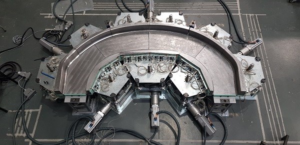
Upper skin layup, INNOTOOL rotating frame
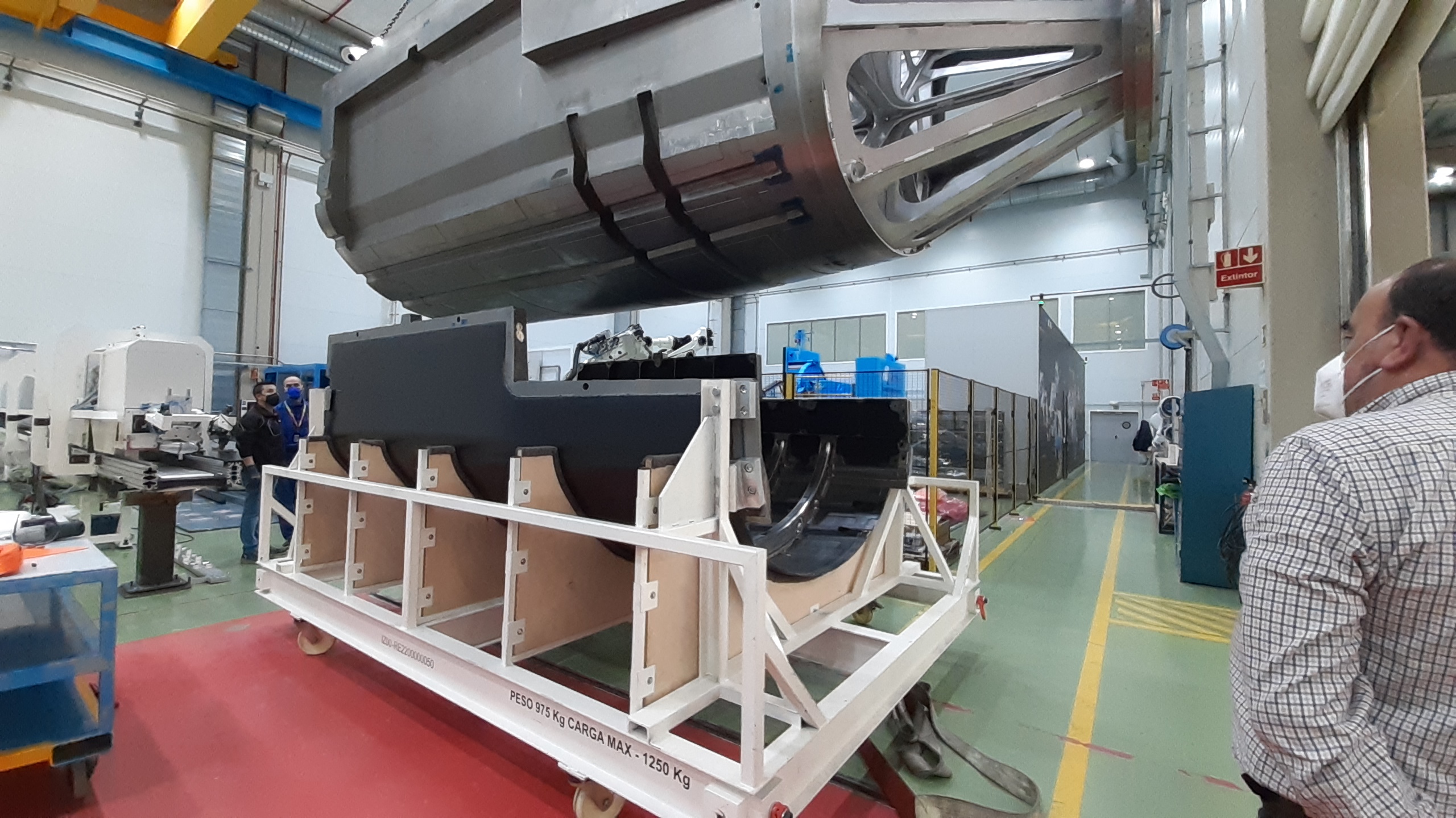
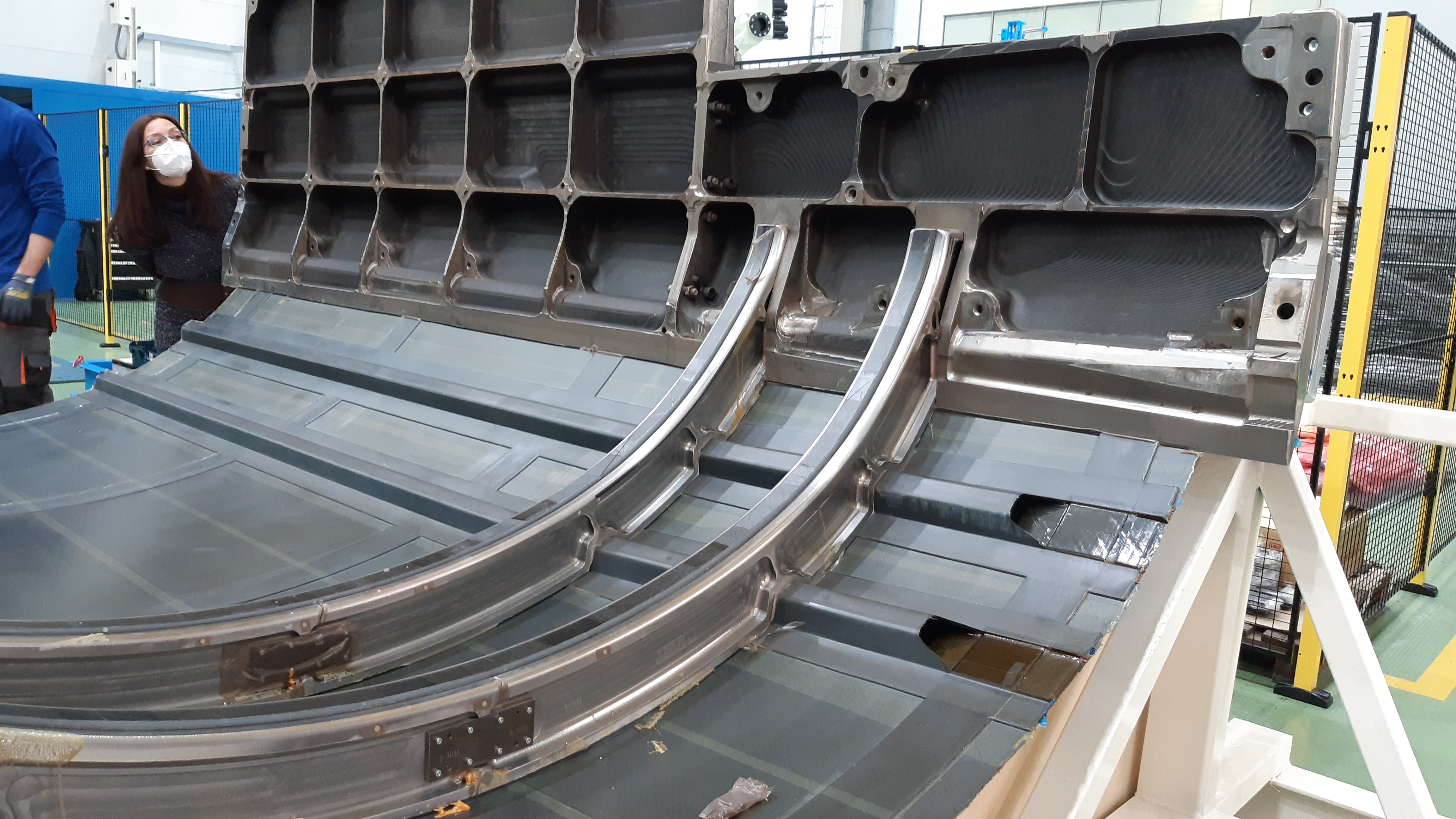
Aernnova developed the fuselage-shaped metal layup tool (top) used by FIDAMC to AFP the upper fuselage skin layup. This was cocured with glide-formed stringers and two shape frames (non-interface frames) for the ARE demonstrator (center). This skin-stringer assembly was then assembled with the RTM frames using a rotating tool developed in the INNOTOOL subproject (bottom). Photo credit: Airbus, Aernnova, FIDAMC, Tekniker and Clean Sky2/Clean Aviation
The stringers were formed (but not cured) in two ways. The first was by Applus+ Laboratories using UD carbon fiber/epoxy prepreg from Hexcel and delivered to FIDAMC. The second was by FIDAMC using hot vacuum forming on a male tool. At FIDAMC, the stringers were mated with the semi-cured contour frames and the ARE demonstrator’s upper fuselage skin layup, made using AFP and the same UD prepreg.
Both the stringer and skin tools were designed and produced by Aernnova. The shape frame and stringer-skin integrated layup was then vacuum bagged and cocured in an autoclave. After cure, this assembly was sent to Aliaga’s team at Aernnova. Next, the RTM’d highly loaded frames would be attached. However, they first had to be positioned onto the skin-stringer assembly in a very precise manner.
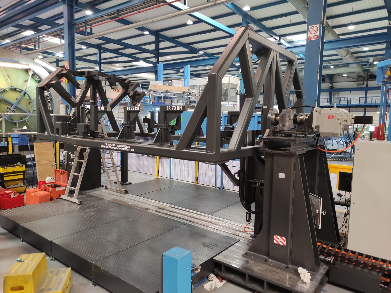
The positioning tool used for this was developed by Tekniker (Gipuzkoa, Spain) in the INNOTOOL subproject with design assistance from Aernnova. “The tool is on a frame that is motor driven and rotates the tool, which holds the skin-stringer assembly,” says Aliaga. “This skin is 3 meters long and 2.5 meters in diameter, which is full scale for the medium-range aircraft specifications used for this demonstrator.”
As the video below shows, the assembly process begins with a laser tracker to build a reference model of the cured skin-stringer assembly. Next, an automated process defines the best fixed points to use for reference during placement of the highly loaded frames. Each frame is identified by the assembly operator who selects, within the control software, which of the load frames is going to be measured and assembled. This software guides the assembly operator through the measurement process and the resulting movement commands to be performed during assembly. The automated measuring is performed by an external metrology framework and driven by a laser tracker using a strategy that was defined beforehand using simulation. The assembly sequence is a complex process where multiple tasks are performed, combining manual and automated operations, including automatic drilling and riveting.
Complex challenges, future promise
The INNOTOOL assembly tooling and metrology-aided process is one example of how the ARE program has explored digital and automation technology to reduce manufacturing time and cost. “That tooling highlights a particular challenge,” says Guinaldo, “in that this rear fuselage has double curvature, and that is part of the complexity of the skin and why it has been so complex to manufacture this demonstrator as well as the highly loaded frames.”
The frames were indeed the most challenging part of the program for Aliaga at Aernnova. However, for Guinaldo, as the demonstrator leader, the biggest challenge was to bring everything together. “This project is more complex than it seems,” he says. “For me, the challenge was to bring the rear fuselage aero-design work together with the airframe manufacturability, assembly and systems installation — to integrate so many disparate parts that have to achieve quite aggressive goals for overall performance.” The next step is to complete physical testing of the frames, he says. “And then we are going to run a virtual test with a nonlinear finite element model in order to validate the frames in the context of the overall rear fuselage.” This virtual test will take place next year.
Although managing so many partners in this project has also been a challenge, it is this large community that has also made it possible — to address so many aspects and develop innovative solutions. “Every person in the team is contributing to making this happen,” he says. “Most people see this as just a rear fuselage, that we are just building something that was clear from the beginning — but that was never the case. We are developing a new airframe and systems concept that is quite disruptive and also quite promising for the next-generation of aircraft.”


Related Content

Co-molding SMC with braided glass fiber demonstrates truck bed potential
Prepreg co-molding compound by IDI Composites International and A&P Technology enables new geometries and levels of strength and resiliency for automotive, mobility.
Read More
Carbon fiber, bionic design achieve peak performance in race-ready production vehicle
Porsche worked with Action Composites to design and manufacture an innovative carbon fiber safety cage option to lightweight one of its series race vehicles, built in a one-shot compression molding process.
Read More
Plant tour: Airbus, Illescas, Spain
Airbus’ Illescas facility, featuring highly automated composites processes for the A350 lower wing cover and one-piece Section 19 fuselage barrels, works toward production ramp-ups and next-generation aircraft.
Read More
Aerospace prepregs with braided reinforcement demonstrate improved production rates, cost
A recent time study compares the layup of a wing spar using prepreg with A&P’s TX-45 continuous braided reinforcement versus traditional twill woven prepreg.
Read MoreRead Next

Hydrostatic membrane consolidation: Skin-stringer panels in 60 minutes
Airbus and Siempelkamp demonstrate press process as alternative to thermoplastic welding, aimed to enable rate 100 aircraft and future mobility manufacturing.
Read More
Ceramic matrix composites: Faster, cheaper, higher temperature
New players proliferate, increasing CMC materials and manufacturing capacity, novel processes and automation to meet demand for higher part volumes and performance.
Read More
Ultrasonic welding for in-space manufacturing of CFRTP
Agile Ultrasonics and NASA trial robotic-compatible carbon fiber-reinforced thermoplastic ultrasonic welding technology for space structures.
Read More