
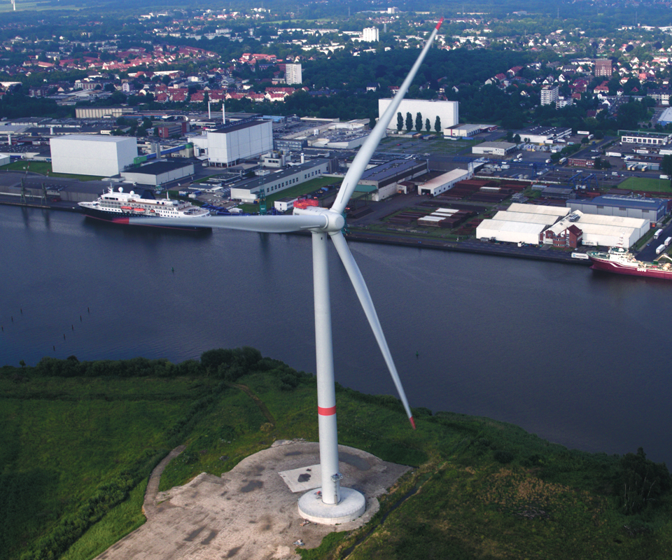
Fig. 1: LM Wind Power’s 88m blades, installed
One set of 3 LM 88.4 P blades, installed by Adwen and running in Bremerhaven, Germany, on this single wind turbine, are said to be capable of powering around 10,000 homes — a small town. Ten similar turbines might power a city.
Source (all photos): LM Wind Power
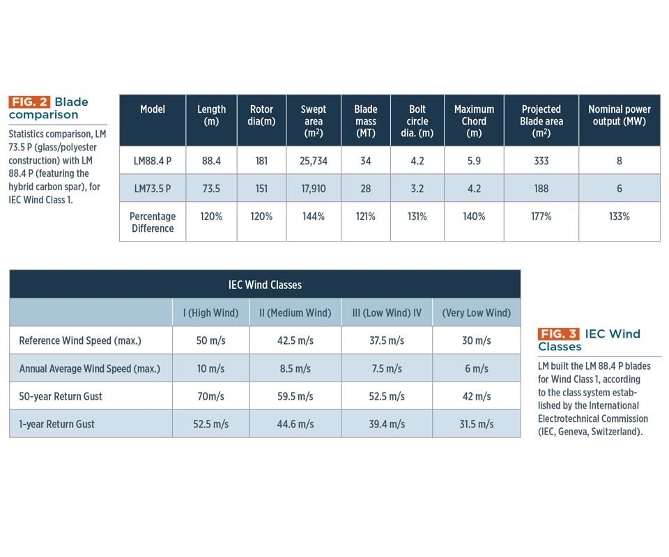
Fig. 2: Blade comparison
Statistics comparison, LM 73.5 P (glass/polyester construction) with LM 88.4 P (featuring the hybrid carbon spar), for IEC Wind Class 1.
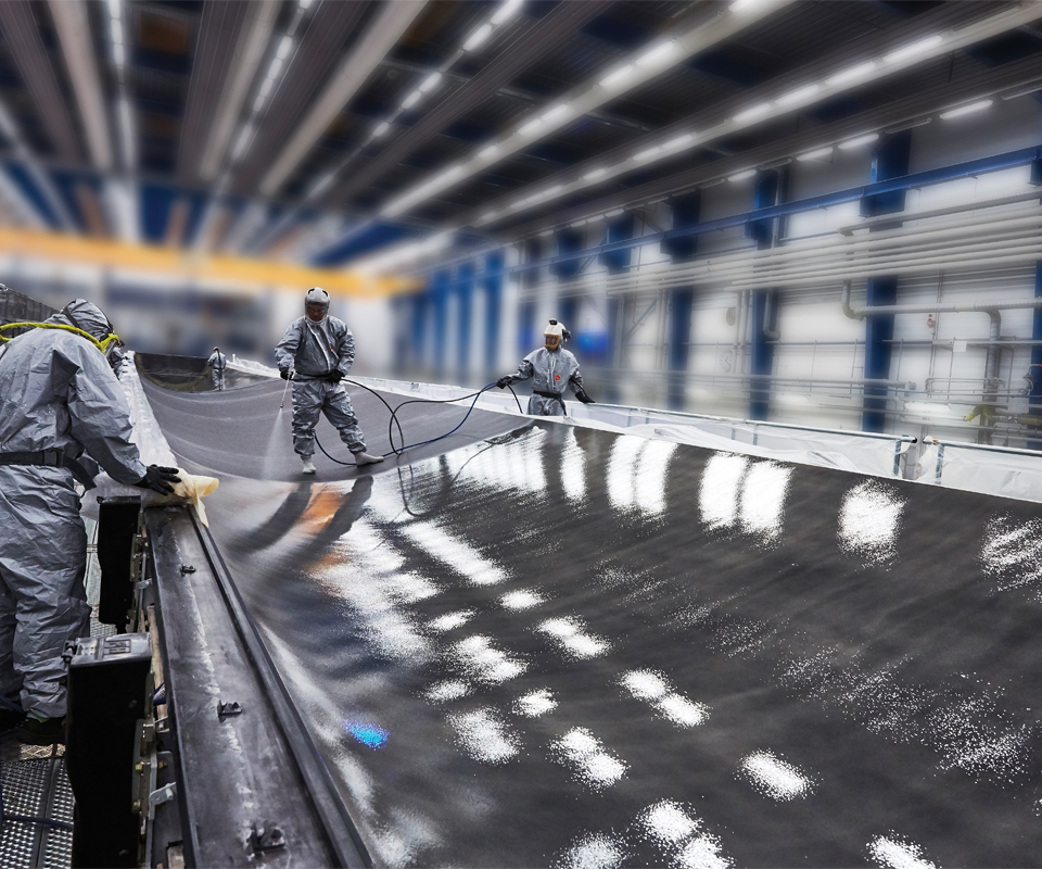
Fig. 3: In-mold finishing
Workers spray gel coat onto mold in preparation for fiberglass base shell layup, eliminating the need for a post-mold painting step.
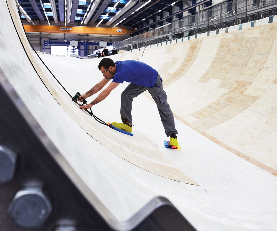
Fig. 4: Core placement
The balsa core is fixed in place by workers.
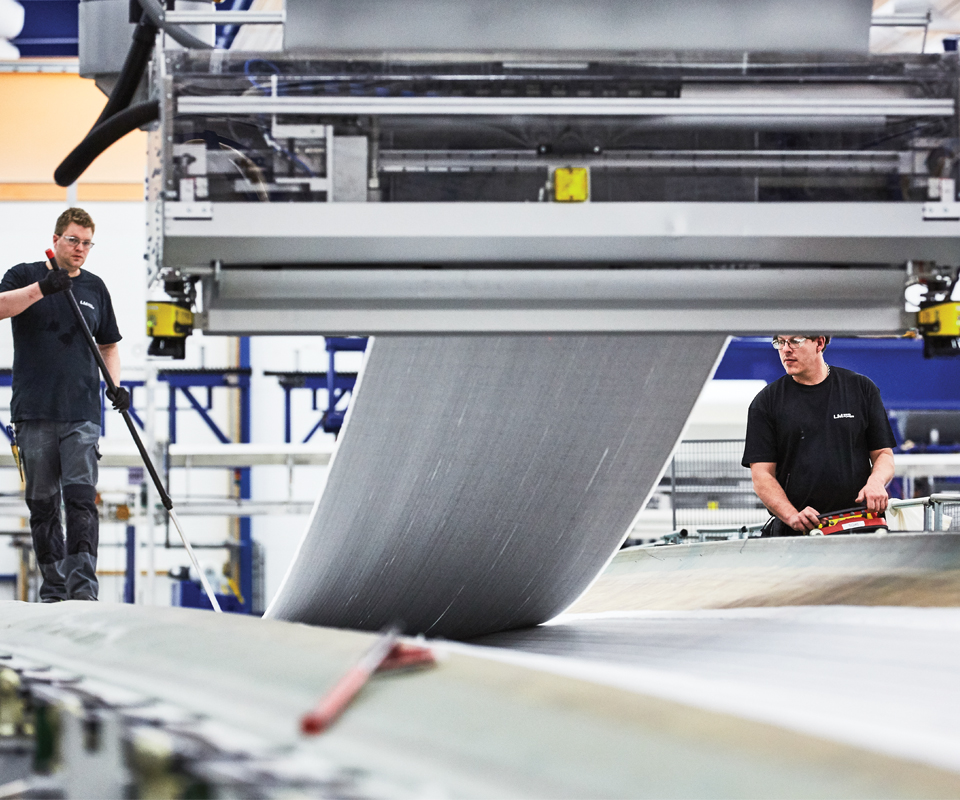
Fig. 5: Dry fabric layup
A semi-automated machine lays lengths of dry fabric along flat center of the mold. The hybrid carbon layup is shown in this photo.
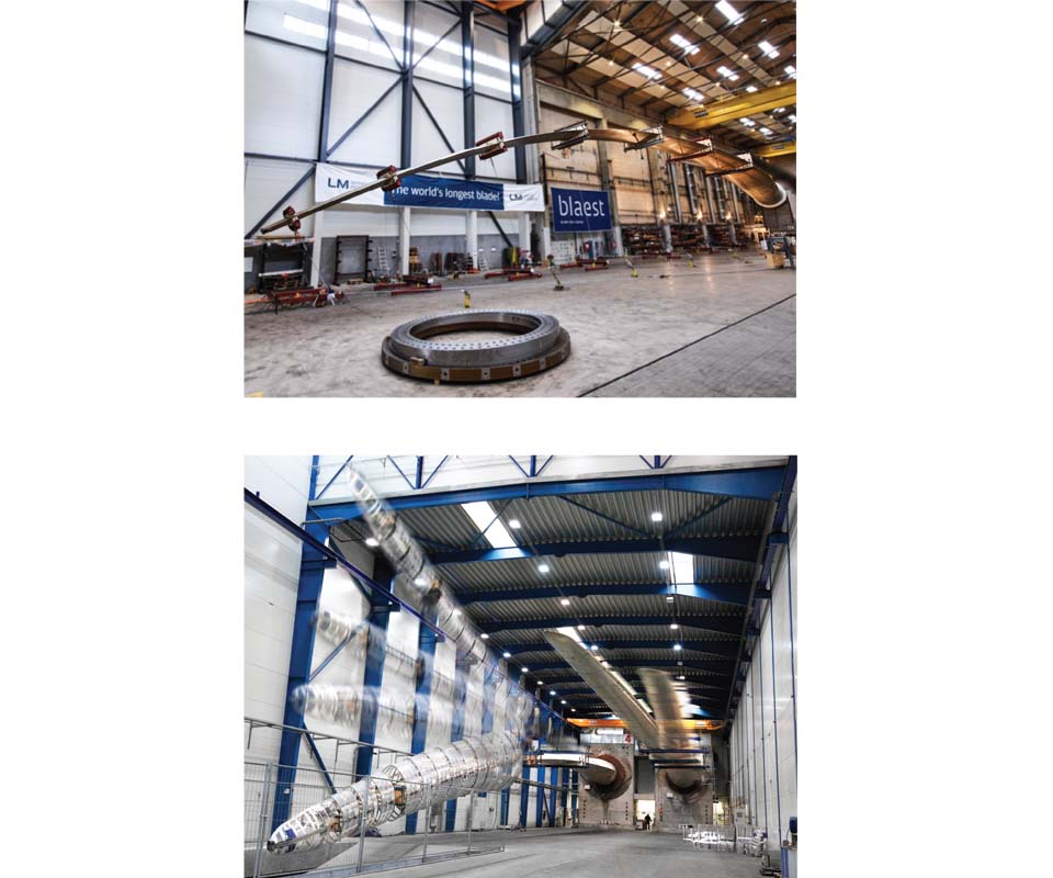
Fig. 6: Static and fatigue testing
Static (top photo) and fatigue (bottom photo) full-scale testing confirms design loads. Flapwise and edgewise loads were generated on the blade using a mechanical exciter, the same principle used during all other LM tests. But in the case of the LM 88.4 P blade, the test regime was beyond what LM had ever attempted in the past. Its lab first had to scale up the test equipment and review and confirm the standard test procedures for the big blade.
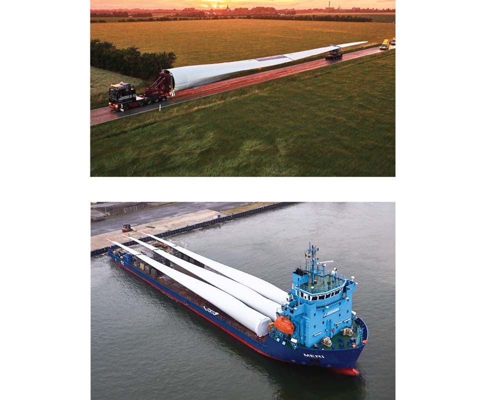
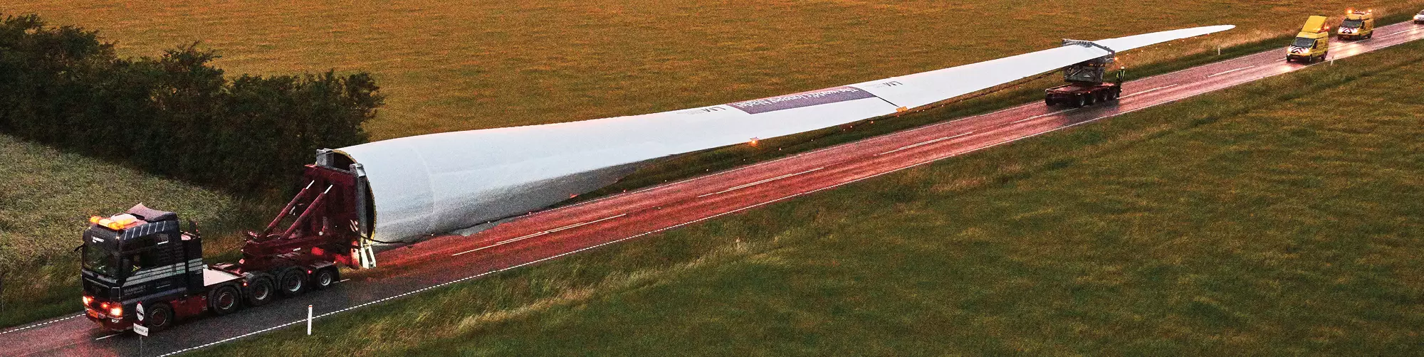
Fig. 7: Transport by truck and barge
The blades’ massive size presented some significant challenges in terms of transportation. Movement was limited to after heavy road traffic hours. Each 60-ton blade made the 218-km trek through Denmark late at night by truck to Aalborg, Denmark (top photo). From there, they were carried by barge (bottom photo) to their final destination in Bremerhaven, Germany.


LM Wind Power’s (LM, Kolding, Denmark) sole product is wind turbine blades. From 1978 through 2016, the company had produced more than 195,000 blades. Recently, LM stretched its skills to produce its first 88.4m wind turbine blades (Fig. 1). Almost as long as a 100-yd American football field, they are the longest blades yet built by any manufacturer. The swept area of a turbine rotor fitted with 88.4m wind blades is large enough to cover three soccer fields and power a small town.
The blade in question, designated LM 88.4 P, is nearly 15m longer than LM’s previously longest blade, the LM 73.5 P, but only 6 MT greater in mass (see Fig. 2). This was accomplished by introducing the lightweight strength and stiffness of carbon fiber into the spar cap laminate.


Other wind blade manufacturers have leveraged the benefits of carbon fiber for more than a decade — primarily through pultruded and carbon/epoxy prepreg spar caps — justifying its higher price through realized performance benefits that enabled competitive levelized cost of energy (LCoE) per megawatt hour. LM, however, is now taking a different approach, embedding a hybrid carbon/glass fiber main spar cap along the length of its standard glass fiber base shell laminate. Saving time and money, the blade shell and spar cap are built in the same tool, with the shell serving as the mold for the hybrid-carbon spar cap. “The LM 88.4 P is the first hybrid blade to be built in this way, using a dry hybrid-carbon layup with a vacuum-assisted resin transfer molding (VARTM) infusion process,” says LM’s Michael Lund-Laverick, director composite technology projects. This hybrid design enabled LM to stretch its core competence to a 88.4m blade within its existing resin-infusion process, without adding another manufacturing process. This strategy met LM’s customer’s design specifications within established cost and schedule targets. ”We chose the solution that was closest to the concept we usually apply, thereby reducing risk and enabling faster development for the customer,” Lund-Laverick says.
The design process for the 88.4m started with the question LM’s engineers ask first on every project: How windy will it be? Customers select one of four wind classes established by the International Electrotechnical Commission (IEC, Geneva, Switzerland), based on the destination wind farm site and on calculated loads (Fig. 3). LM’s customer for the 88.4m blade, Adwen (Bremerhaven, Germany, now part of Siemens Gamesa Renewable Energy, Zamudio, Spain), specified Wind Class I (high wind) for offshore sites. LM, accordingly, designed the blade for 50 m/sec (112 mph) Reference Wind Speed and other Class 1 requirements.
Design drivers for new products: uncertainties and risk
Next, the design was driven by LM’s uncertainty management strategy. “This approach tackles the highest uncertainties first — the worst failures that can be conceived,” explains Lund-Laverick. It starts with LM’s failure modes effects analyses (FMEAs). An FMEA is a formal analysis tool for evaluating the risk for a design (dFMEA) or a process (pFMEA). This consists, first, of engineers verbally brainstorming possible risks before turning to computer assistance. “In this way, we manage new projects by managing their risks, relying on the company’s deep engineering knowledge, experience and communication to define the key showstoppers. Our engineers think about all the doom-and-gloom things that could possibly happen, and then think of tests and engineered solutions to ensure those things do not happen,” Lund-Laverick explains.
The discoveries of these FMEA sessions determine what real tests and trials need to be conducted — actual sample parts are made and tested to verify design limits and failure modes before computer modeling and analysis begins. “The computer models are then based on a kind of reality,” Lund-Laverick says, instead of preliminary theory — no matter how astute that theory may be.
After wind class, design limits and failure modes were established, engineers used LM Blades, the company’s suite of design programs and 3D modeling software, to bring the big blade within established limits for static and dynamic fatigue load Markov Matrices (for variations over time); buckling of the large aero panels; Puck fracture criteria for strength of unidirectional fiber/matrix (Alfred Puck, Immenhausen, Germany); and other mechanical/strength and chemical/environmental requirements.
Hybrid carbon/glass fiber, the best of both worlds
LM’s hybrid technology consists of the company’s standard glass fiber/polyester base shell laminate strengthened by a hybrid carbon/glass fiber main spar cap. Glass fabrics for the shell are woven to LM’s specifications by a variety of glass and fabric suppliers, typically including H-glass fiber, supplied by Owens Corning (Toledo, OH, US). The shell laminate is a structural sandwich with a balsa wood core, infused with LM’s standard polyester resin.
For the spar cap, uniaxial carbon/H-glass hybrid fabric is manufactured by Devold AMT AS (Langevaag, Norway), a subsidiary of SAERTEX GmbH & Co. KG (Saerbeck, Germany), which received LM’s Most Innovative Partner 2017 award for this fabric. Fiber architecture for both the base shell and the spar cap consists of a mixture of ±45° biaxial fabric, 0°, ±45° combination fabrics, and 0° unidirectional (UD) fabrics in differing areal weights. Developed with the LM team, this fabric was used for the first time in the 88.4m blade, infused with an unidentified, but proven LM resin to achieve target blade properties. The proprietary resin system used for spar cap infusion is based on the chemical backbone of other systems that have shown excellent chemical attachment and adhesion to the polyester resin used in the shell structure, Lund-Laverick says.
Hybrid carbon manufacturing strategy
The blade is constructed in two halves — an upwind (upper) half and a downwind (lower) half — which are mated after cure. Each blade half carries a hybrid spar cap. The manufacturing strategy for the hybrid carbon development consists of a two-stage infusion process, based on VARTM: In the first stage, the shell, which includes all elements of the blade except the spar cap, is built up in the following sequence:
•Gel coat applied to 88.4m mold (Fig. 4).
•External biaxial fiberglass shell coverage layers are arranged.
•Root and edge reinforcements are applied, primarily UD materials.
•Balsa core is positioned in place for sandwich panel construction and retained with small fasteners (Fig. 5).
•Internal biaxial layers are added (Fig. 6).
•Vacuum bag is attached and standard LM polyester resin is infused via VARTM process.
•Part is cured at room temperature, according to proprietary LM specifications.
•After cure, the base shell is de-bagged and inspected to prepare it for the next stage.
In the second stage, the hybrid main spar cap is then built up on top of the cured base shell, using the cured shell as a mold:
•Hybrid UD carbon/glass fabric layers are applied directly over the base shell, starting 4m from the root.
•LM-designed lightning protection components are added.
•Standard ±45° biaxial fiberglass coverage layers are arranged.
•Vacuum bag and VARTM infusion, carefully controlled to infuse only the carbon layup with a specially developed resin system.
•Part is cured at room temperature, according to proprietary LM specifications.
“We were able to scale-up our standard manufacturing process for our increasingly long blades,” Lund-Laverick says. On these huge blade halves, the sides curve up but the center of the structure is essentially flat,” he adds, “with only a gentle curve in the length direction due to pre-bending of the blade.” For the flat sections of the blade halves, LM’s in-house-designed, computer-controlled, semi-automated machine lays down wide sheets of dry fabric in programmed layers to meet strength requirements.
The curved sides, however, present more complex geometries that generally must be layered by hand.
The machine was used for both the base shell and the hybrid spar cap. “For the hybrid carbon fabric, which is more sensitive than normal glass,” Lund-Laverick says, “we developed a hands-off layup process to avoid wrinkles and other potential defects from manual handling.”
The spar web is a fiberglass/foam sandwich structure made using primarily biaxial layers and infused with the standard polyester resin.
For quality control, LM employs the Six Sigma (Austin, TX, US) methodology. “During production, there is a strict suite of quality-control documents and procedures,” including continual visual inspection of the blade, Lund-Laverick says. After cure, ultrasonic and visual inspection ensure the quality of the laminate. Following these inspections the blade halves were adhesively bonded in conventional fashion.
Closure and post-cure operations
After blade halves were adhesively joined, LM added its vortex generators, which compensate for the fact that large blades demonstrate relatively poor aerodynamic performance near the root. Designed for individual blade geometry and resembling small fins, they are injection molded and then adhered to
the outer blade surface on the downwind shell, typically from about 5m from the root to about the middle of the blade during final blade assembly, using VHB tape, supplied by 3M Advanced Materials Div. (St. Paul, MN, US). These reduce flow separation (air separating from the blade before reaching the trailing edge) and improve lift and energy output. Additionally, LM installs proprietary, custom-designed spoilers on the inboard blade section, near the root, to further increase lift. These are made by reaction injection molding (RIM).
Destiny to be determined
The LM 88.4 P blade passed static and fatigue full-scale tests at LM’s facility and at the independent Blaest Blade Test Center in Aalborg, Denmark (Fig. 7). The blade subsequently was certified by DNV GL AS (Oslo, Norway). The first commercial LM 88.4 P blades were destined for installation in Adwen’s next-generation AD 8-180 wind turbine, with 8 MW nominal capacity and a 180m rotor diameter. LM manufactured three blades, which were transported by truck and barge (Fig. 8, p. 35), installed by Adwen, and are running on one grid-connected turbine in Bremerhaven, Germany (opening photo, p. 32). LM “delivered the required blades and completed the DNV certification according to the original time plan,” says Lund-Laverick. The overall project, however, became a casualty of industry consolidation: Adwen was acquired by Gamesa, which subsequently merged with Siemens, followed by Siemens Gamesa Renewable Energy’s (Zamudio, Spain) cancellation of the AD 8-180 platform, for which the LM 88.4 P had been developed.
Lund-Laverick says LM Wind Power continues to drive hybrid carbon fiber spar platform development and is now delivering it on 69.3m blades for Siemens Gamesa. This onshore turbine blade design — for the world’s largest onshore rotor — uses the same design, material and manufacturing principles developed for the 88.4m blade and continues to leverage the hybrid carbon and resin system technology benefits to drive the LCoE ever lower. He adds that future hybrid blade construction depends on customer requirements, but says as blades grow longer, LM expects an increasing number will be built using the hybrid technology.


.jpg;maxWidth=300;quality=90;format=webp)
Related Content

Coriolis Composites installs AFP machine at Sabanci University
C1 robot contributes to technology development at the Integrated Manufacturing Technologies Research and Application Center (SU IMC) in Istanbul.
Read More
Materials & Processes: Fabrication methods
There are numerous methods for fabricating composite components. Selection of a method for a particular part, therefore, will depend on the materials, the part design and end-use or application. Here's a guide to selection.
Read More
University of Maine unveils 100% bio-based 3D-printed home
BioHome3D, made of wood fibers and bioresins and entirely 3D printed, highlights Maine’s effort to address the need for more affordable housing.
Read More
Composites UK launches best practice guide for composites tooling
“Mould Tooling for Fibre-Reinforced Polymer Composites” is latest in Composites UK’s series of good practice guides, available online for free.
Read MoreRead Next

CW’s 2024 Top Shops survey offers new approach to benchmarking
Respondents that complete the survey by April 30, 2024, have the chance to be recognized as an honoree.
Read More
Composites end markets: Energy (2024)
Composites are used widely in oil/gas, wind and other renewable energy applications. Despite market challenges, growth potential and innovation for composites continue.
Read More
From the CW Archives: The tale of the thermoplastic cryotank
In 2006, guest columnist Bob Hartunian related the story of his efforts two decades prior, while at McDonnell Douglas, to develop a thermoplastic composite crytank for hydrogen storage. He learned a lot of lessons.
Read More