
A350 XWB update: Smart manufacturing
Spirit AeroSystems actualizes Airbus’ intelligent design for the A350’s center fuselage and front wing spar in Kinston, N.C.

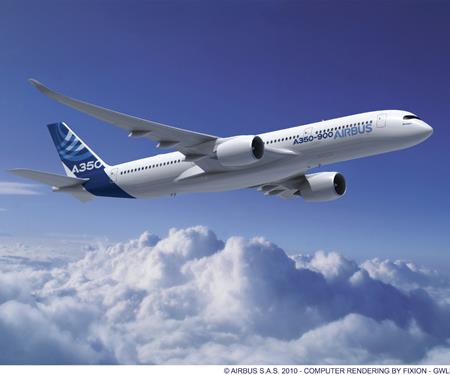
Assembly of the first Airbus A350 XWB, an A350-900, is underway. Major fuselage and wing components will flow from Spirit AeroSystems’ Kinston, N.C. plant to Europe, toward final assembly in Toulouse, France, near the end of next year. Source: Airbus
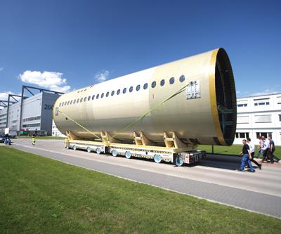
This panelized A350 fuselage section, at 18m/59-ft long and more than 6m/19.7 ft in diameter was the second ever made, and closely reflects the A350 XWB fuselage’s final design. Although it was constructed of 12 panels, the panels used in production sections will run the length of the barrel. Source: Airbus
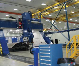
This Electroimpact (Mukilteo, Wash.) S-15 dual-head automated fiber placement (AFP) machine will form the panels for the A350’s center fuselage (Section 15) at Wichita, Kan.-based Spirit AeroSystem’s plant in Kinston, N.C. Source: Spirit AeroSystems
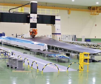
The A350 wingskin is tape layed in one piece on a massive tool, using an automated tape layer (ATL) built by MTorres (Torres de Elorz, Spain). Source: MTorres
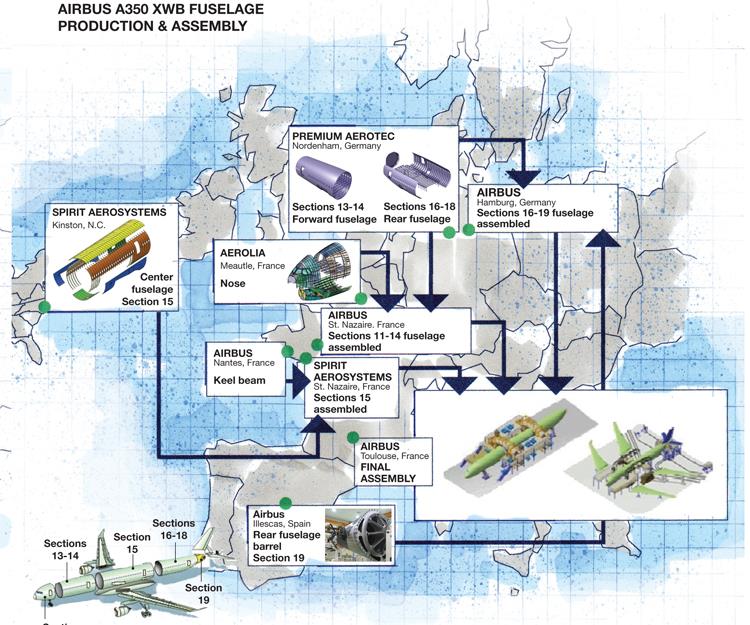
Airbus A350 VWB Fuselage Production & Assembly Diagram
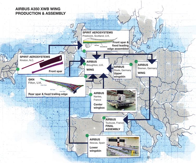
A350 XWB Wing Production & Assembly Diagram
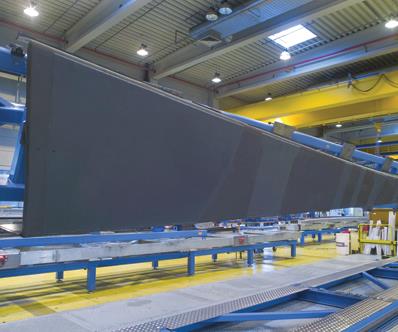
This early version of the A350 wing’s inner spar was produced using a TORRESLAYUP AFP system, built by MTorres (Torres de Elorz, Spain). Source: GKN Aerospace
Share
Read Next

The long wait is nearly at an end.
Final assembly of the first Airbus (Toulouse, France) A350 XWB midsize passenger jet, an A350-900, is expected to begin by the end of this year and be completed by the fourth quarter of 2012, in time for its scheduled first flight. Assembly of its major fuselage and wing components is now underway. The forward and center sections will ship from the Airbus facility in Saint-Nazaire, France, and the rear fuselage will come from the Airbus plant in Hamburg, Germany. For each aircraft produced, the new final-assembly line in Toulouse will receive the three sections of the fuselage already equipped with wiring harnesses, hydraulics and cabin systems, such as air conditioning. The plane’s wings will be assembled by Airbus in Broughton, U.K., and equipped at its Bremen, Germany, plant before they are sent to Toulouse (see pp. 58-59).


The center fuselage (denoted section 15 by Airbus) is the longest of the three, at 65 ft/20m. Section 15 is built up from six sizeable composite panels made by Spirit AeroSystems (Wichita, Kan.). Manufactured at Spirit’s 682,000-ft2/63,360m2 facility, which opened last July in the U.S. (Kinston, N.C.), these components exemplify a distinct design approach adopted by Airbus in pursuit of not only the weight and performance benefits of composites, but also ways to address potential issues, such as lack of electrical conductivity, without increased cost (see “Panelized option attested early on,” under "Editor's Picks," at top right).
Also part of Spirit Kinston’s scope of work for the A350 are the three-piece, all-composite 102-ft/31.2m front spars for the wings. The three-part forward spar aids in assembly at the Airbus Broughton wing plant and avoids bottlenecks (like those experienced in the A380 and Boeing 787 programs), which will help maximize monthly production.
For the center fuselage and front wing spar, Spirit’s “intelligent design” also incorporates “smart manufacturing” practices. Large components are built up from simpler, more easily manufactured subcomponents that are also easier to repair and maintain. Smart manufacturing concepts also inspired many features of Spirit’s Kinston plant, including a physical layout that improves workflow and the latest automated fiber placement technology to increase productivity.
Spirit has specifically designed the Kinston facility for growth and easy adaptability to new technologies. The plant is laid out around a central transportation aisle, from which cleanrooms, autoclaves and paint booths emanate. The layout speeds component flow through the plant. This configuration also permits plant supervisors to add extra processing modules, as necessary, to relieve bottlenecks. And it will accommodate new processes in the future. The ability to adapt to the changing production needs of its customer, Airbus, is a key focus for Spirit. The 574 orders currently on the Airbus books for the A350 XWB “is a large number of planes,” points out Dan Wheeler, a Spirit VP and the general manager of the Kinston facility. He adds, “We have set up production here to be able to meet Airbus’ schedule as production ramps up.”
Intelligent design: Fuselage
A notable characteristic of the A350 design is that the main fuselage comprises three long sections. The forward and aft sections are each made from four large composite panels (crown, keel and two sides). But the center fuselage adds two lateral junction panels that help connect the fuselage to the wings. Section panels are attached to a combination of composite and metal frames. By contrast, the 787’s fuselage uses four shorter, one-piece composite barrels. Airbus opted for large fuselage panels, instead of unitized complete fuselage barrel sections, because they can be tailored in terms of their laminate sequence and thickness according to the different loads borne by each part of the airframe. This reportedly enables a fuselage optimized for performance and weight. The use of fewer, longer sections also means fewer joints that are said to be better placed for load and weight optimization. This design is expected to avoid the fit issues Boeing had when it joined the first 787 barrels made with totally different tooling approaches, and it facilitates manufacture and assembly via easier parts handling, less complex and lighter tooling, and less expensive and faster section production.
Because the fuselage sections’ carbon fiber composites do not conduct electricity as well as aluminum alloy structures, the current from a lightning strike will seek any metal paths available, such as fasteners. For this reason, both the 787 and the A350 make strategic use of metal parts. Selections were made based on the parts’ ability to provide necessary structural reinforcement in some highly loaded regions while facilitating an electrical return path for the internal electrical systems and equipment. All of the A350’s metal parts — including aluminum seat rails and a mix of aluminum, aluminum/lithium alloy and titanium for lower frames and passenger cabin structural floor grid beams — do double duty. Each part has a structural function, and it also forms part of the overall electrical structure network (ESN) within the aircraft. The A350’s composite panels incorporate an outer copper mesh to manage the direct effects of lightning, and they work with the ESN to maintain the Faraday cage principle, channeling the electrical current around the fuselage harmlessly rather than letting it pass through to damage fasteners and operational structures. This multifunctionality avoids added structure associated with dedicated ESN components and the resulting weight penalty that would offset the lightweighting advantage of a CFRP fuselage. As a result, the six assembled sections of the center fuselage, at 64.6 ft/19.7m long and 22 ft/6.7m in diameter, will weigh a mere 9,000 lb/4,082 kg.
Intelligent design: Wing
The A350 wing design also benefits from topology optimization, a finite-element-based analysis that determines the most efficient material layout for a structure (see “Topology optimization,” under "Editor's Picks"). This technique was used, and its benefits were proven, for a variety of structures that make up the A380 wing, including the leading-edge stiffening ribs. For the A350, topology optimization was employed earlier and more extensively as Airbus sought higher performance within a more efficient design process with less cost.
In addition to the all-composite front spar, advanced composite materials enable passive and active load-control mechanisms that improve the A350 wing aerodynamic and structural performance. Passive adaptivity is achieved using aeroelastic tailoring, a design technique for aerodynamic surfaces in which strength and stiffness are matched with the likely aerodynamic loads that may be imposed on them. The A350 composite wing also takes advantage of maneuver load alleviation (MLA), which provides active load control. MLA is a system for reducing wing bending moment load during aircraft maneuvers. The digital flight control system automatically adjusts the control surface deflections along the span of the wing to optimize and evenly manage the loads, from the wing root all the way to the wingtip.
Another aspect of this design is variable camber. The A350 will be the first Airbus aircraft capable of this function, which will rely on a wing flap system that allows for differential inner and outer flap settings. A gearbox and motor are mounted between the outer and inner flap, enabling differential control of each flap’s angle after they have been retracted. The center-of-lift position also can be changed for load management. For example, the inner flap can be set slightly down, shifting the center of lift inboard for heavy weight situations. It is also possible to move both flaps together up or down a small amount, which improves wing performance by tuning the peak-lift-over-drag ratio. During cruise, the flap functions will be controlled automatically by the flight control system computers, which continuously sense data from the flight management system.
The overall result is an extremely efficient wing that produces more lift with less weight and is capable of advanced load handling performance that also helps to reduce the aircraft’s fuel burn.
Manufacturing: Center fuselage
Section 15 is not only the largest fuselage section, but also the most complex. Four of its panels have constant-contour surfaces, but because it is adjacent to the wing, the two lateral junction panels (see dark blue parts in “Center Fuselage Section 15,” on p. 59) have both convex and concave curvatures, which provide an aerodynamic fairing and structural connection to the all-composite wingbox.
The manufacture of section 15 begins with an Electroimpact Inc. (Mukilteo, Wash.) S-15 dual-head automated fiber placement (AFP) machine that was specifically designed for these large structures. ElectroImpact engineered the S-15 to perform on-the-fly feeding and cutting and fully bidirectional layup over ramped, complex surfaces within customer placement tolerances and with full operator control over the feed rate at speeds up to 2,000 inches/min (50.8m/min). Necessary for the large fuselage panels, the high speed was achieved by re-engineering the guillotine-type cutting system and optimizing the feed, tow path and creel and machine-control systems.
The machine lays up Hexply M-21E carbon fiber/toughened epoxy prepreg from Hexcel (Stamford, Conn.) onto a male Invar tool. (The first section 15 crown panel was completed in November 2010.) All of section 15’s panels incorporate integrated CFRP stringers, which are produced using a cantilever-type AFP machine built for high-speed 2-D lamination by MTorres (Torres de Elorz, Spain). The stringers then are placed onto the composite panel layups and cocured under vacuum in one of two 80-ft/24.4m long by 22-ft/6.7m diameter autoclaves. (The first has been installed; the second will be added as production increases.)
An automated TORRESMILL router removes the window and door cutouts from the large side panels. MTorres also supplied Spirit’s two 5m/16.4-ft tall columnar ultrasonic (UT) inspection machines, each with a separate array of UT scanners, to achieve simultaneous inspection of inner and outer skins for each fuselage panel. After inspection, the finished composite panels are attached to the fuselage frames. Most of the frames are composite, but a few are aluminum to support the ESN. Additionally, the door surrounds are titanium. The frames and surrounds are attached with automated equipment.
After they are completed, the Section 15 panels will be nested into a 70-ft/21m container. They will be transported by road to Morehead City, N.C., or another port in that state, and then by ship to the Spirit AeroSystems facility in Saint-Nazaire, which is located near Airbus’ Aerolia facility in northwest France. Spirit’s 60,000-ft2/5,574m2 plant in Saint-Nazaire is an assembly-only facility (officially opened July 23, 2010 and operational later that year) where the three upper shell panels are joined together with the forward and aft passenger floor. The remaining three panels are shipped loose and installed by Airbus Saint-Nazaire on the section 15 unit. Afterwards, the section will be mated with the center wingbox, which will arrive from Airbus Nantes (located 50 miles/80 km to the east), and equipped with piping and other systems. Then the center fuselage/wingbox unit will ship by air to Toulouse for final aircraft assembly.
Producing forward wing spars
The A350’s forward wing spar, a 102-ft/31.2m long structure, is the largest spar Spirit has ever made, and it is Spirit’s first all-composite spar. The structure comprises three parts from root to tip: a 7m/23-ft long inner spar, a 12.7m/42-ft long middle spar and an 11.5m/38-ft long outer spar.
The spar parts are made with up to 100 plies of CFRP, tapering from a width of 6 ft/1.8m at the root of the inner spar to, roughly, a width of 1 ft/3.3m at the tip of the outer spar.
MTorres has been a key partner in developing Spirit’s spar production capability. Two of the company’s TORRESFIBERLAYUP AFP systems were specially designed to provide greater flexibility and productivity than would be available with either conventional gantry or column-type machines. Reportedly, these AFP systems are capable of layup rates as high as 2,360 inches/min (60m/min), an order of magnitude greater than previously possible and key to making the spar production process in Kinston economically viable. MTorres has delivered similar equipment to GKN Aerospace’s (Redditch, Worchester, U.K.) new facility near Filton, U.K., for production of the A350’s rear wing spar. These machines were developed to achieve the tight U-shaped geometry along the spar components’ edges — where many issues arise when 45° material is applied over 90° corners. The machine heads also deliver the higher temperature and greater compaction pressure required to successfully process the relatively low-viscosity Hexply material — the same M-21E toughened epoxy prepreg that is used to layup the fuselage panels. Each of the MTorres machines can lay two spars simultaneously on 15m/49-ft Invar mandrels, which are then transferred to the autoclave for curing.
The cured spar components are checked for quality, using an automated gantry-based TORRESONIC UT inspection machine, measuring 15m/49.2 ft long and 2m/6.6 ft wide. MTorres built the frame and attached a commercially available robot by Kuka Roboter GmbH (Augsburg, Germany), with electronics supplied by Tecnatom SA (Madrid, Spain). The finished spar sections are shipped to Spirit’s Prestwick, Scotland, facility, where they are joined together, mated with the fixed leading edge and other fixtures, then delivered as a complete leading edge assembly to Airbus’ Broughton facility for final assembly with the A350 wing. The first complete outer spar was shipped Dec. 10, 2010.


.jpg;maxWidth=300;quality=90;format=webp)


Related Content

Carbon fiber in pressure vessels for hydrogen
The emerging H2 economy drives tank development for aircraft, ships and gas transport.
Read More
JEC World 2022, Part 3: Emphasizing emerging markets, thermoplastics and carbon fiber
CW editor-in-chief Jeff Sloan identifies companies exhibiting at JEC World 2022 that are advancing both materials and technologies for the growing AAM, hydrogen, automotive and sustainability markets.
Read More
Cycling forward with bike frame materials and processes
Fine-tuning of conventional materials and processes characterizes today’s CFRP bicycle frame manufacturing, whether in the large factories of Asia or at reshored facilities in North America and Europe. Thermoplastic resins and automated processes are on the horizon, though likely years away from high-volume production levels.
Read More
Materials & Processes: Resin matrices for composites
The matrix binds the fiber reinforcement, gives the composite component its shape and determines its surface quality. A composite matrix may be a polymer, ceramic, metal or carbon. Here’s a guide to selection.
Read MoreRead Next

Boeing 787 Update
Approaching rollout and first flight, the 787 relies on innovations in composite materials and processes to hit its targets
Read More