


In many four-wheel drive and all-wheel drive vehicles, steel driveshafts are segmented to provide necessary torque and vibrational performance characteristics. Unlike these segmented steel counterparts, a one-piece carbon fiber-reinforced polymer (CFRP) automotive driveshaft is able to provide the required performance as it spans the full distance from transmission to differential, typically between 1,000 millimeters (passenger cars) and 3,000 millimeters (commercial vehicles). A single CFRP driveshaft can therefore replace not only the steel driveshaft, but also the flanges and intermediate bearings that join the two segments. As a unified component, the CFRP driveshaft enhances performance, contributes less weight and has proven to be cost-competitive in high-performance vehicles.
But is CFRP still a viable option when span is no longer a factor?


This is the case when it comes to output shafts, which connect the short distance (typically 250 to 500 millimeters) from the drivetrain to the wheels. Exploring whether the case could be made for CFRP output shafts on production vehicles, the design team at Dynexa (Laudenbach, Germany) was pleasantly — and admittedly — surprised by the results.
Dynexa, a filament winding and driveline company and a member of the Avanco Group (Herford, Germany), undertook its design and demonstration of a CFRP output shaft as part of a predevelopment study conducted with a German OEM. In 2014, Dynexa began supplying the OEM with CFRP driveshafts that achieved a 40% weight reduction compared to a segmented steel shaft and intermediate bearings. The accompanying reduction in rotating mass also improved the vehicle’s driving behavior.
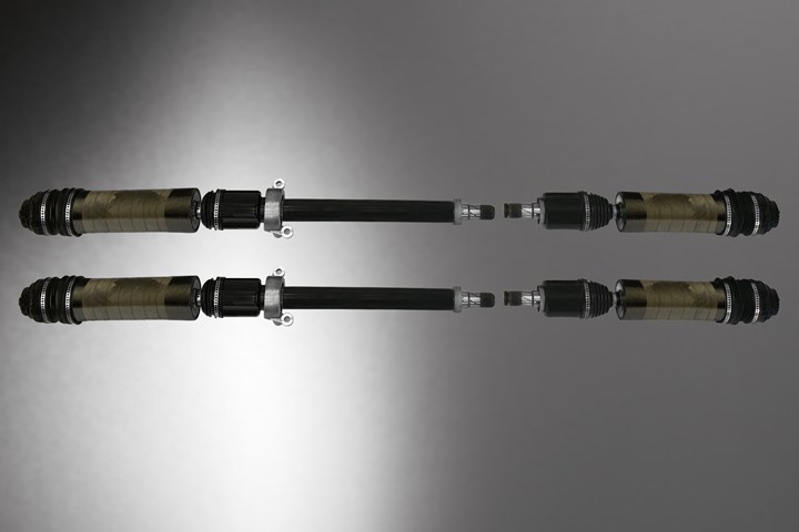
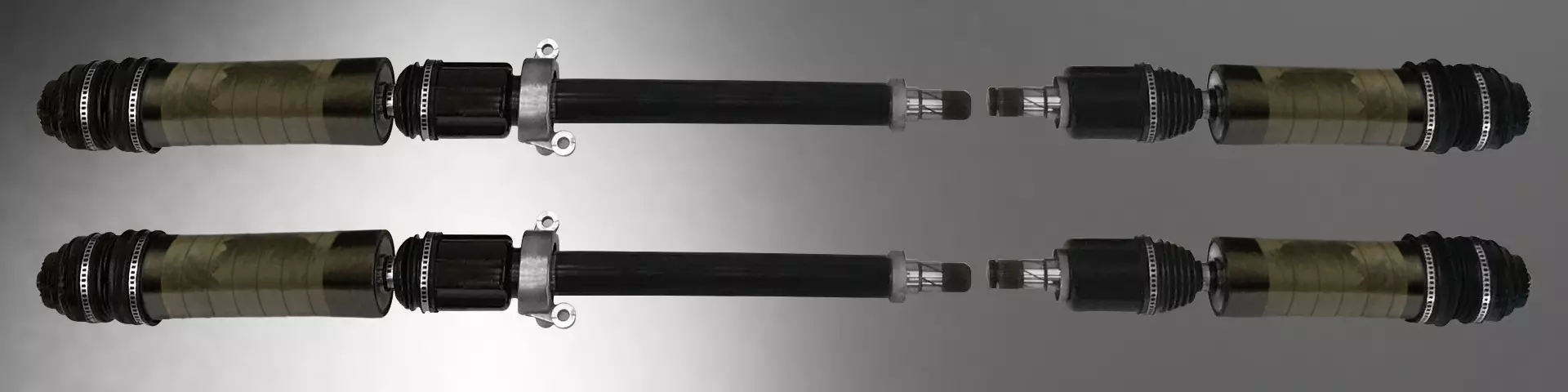
Ready to roll. CFRP output shafts, shown here in two complete assemblies, have demonstrated a tailorable stiffness with the potential to improve vehicle driving behavior. Source | Dynexa
Since 2006, Dynexa has filament-wound more than 100,000 CFRP tubes and shafts for automotive prototype and serial production applications. The company typically employs an epoxy matrix supplied by Huntsman (The Woodlands, Texas, U.S.) or Hexion (Columbus, Ohio, U.S.). Dynexa works with many major carbon fiber suppliers, including Teijin (Chiyoda-ku, Japan), Toray (Tokyo, Japan), SGL (Wiesbaden, Germany), Mitsubishi (Tokyo, Japan), and Nippon Graphite Fiber Corp. (Himeji, Japan). (Fiber for each application is selected according to product and production requirements, making the best use of material properties.) Even with this history and breadth of experience, though, the Dynexa team initially harbored doubts about the use of CFRP for output shafts.
From doubt to demo
A solid metal output shaft is the norm today in production vehicles, and at first the Dynexa team was unsure what value a CFRP alternative might bring. “In contrast to multi-part metal driveshafts, we would not achieve high weight savings here,” notes Matthias Bruckhoff, head of sales and marketing for Dynexa.
Why switch to CFRP output shafts? CFRP’s high performance could be potentially useful in electric vehicles, in which output shafts are subject to unusually high forces. Additionally, the CFRP output shaft may also prove useful on both electric and gas-powered vehicles because of a phenomenon common to all types of automotive powertrains. Called “power hop,” the phenomenon occurs when low-friction road surfaces cause the tires in front-wheel-drive vehicles to cyclically lose grip with the drive surface during high engine acceleration. “The driver hears a loud, cyclical rattling of the front axle and feels a strong vibration on the seat and steering wheel,” explains Linda Senger, BMW research of hybrid powertrain, mechanics and structure. Power hop occurrence is highly dependent on the output shaft and its torsional stiffness.
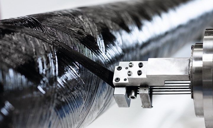
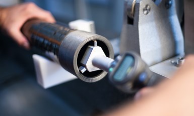
Filament-winding application. Having filament-wound more than 100,000 CFRP tubes and shafts for automotive prototype and serial production applications, Dynexa applied this experience to the new challenges that the output shaft application presented. Of particular interest are the vibrational performance and torsional stiffness of the shafts. Source | Dynexa
“The focus of the development was the influence on power hop of higher torsional damping in CFRP output shafts compared to steel shafts with the same torsional stiffness,” Senger continues. CFRP shafts have been shown to possess five to 10 times the torsional damping of steel shafts. This damping behavior is adjustable to the requirements of the application.”
Generally, automotive designers seek to modify the vibration characteristics of vehicle components in order to minimize noise, vibration and harshness (NVH). “When you push the throttle,” explains Marcus Schwarz, head of product development at Dynexa, “it increases force and vibration into the system, causing NVH.” Dynexa’s team is experienced in optimizing the vibrational characteristics of CFRP components. “By designing the fiber composite structure and adjusting the layer structure, a desired frequency can be achieved to influence the dynamics of the part during the run," Schwarz says.
Testing of the CFRP shaft demonstrated the importance of torsional stiffness to power hop reduction.
The differing vibrational characteristics of CFRP and steel are central to Senger’s output shaft study. To test whether CFRP vibrational damping would help reduce power hop intensity, Senger provided Dynexa with a set of design parameters for the CFRP output shaft. Because the test would be conducted on an existing assembly for a gas-powered vehicle, including the gearbox connection and joints, the CFRP shaft needed to be designed as a direct replacement for the metal shaft.
Dynexa designed the CFRP shaft to match the metal shaft’s ability to handle a static torsional load of up to 3,000 Newton-meters. Importantly, the CFRP shaft also had to match the metal shaft’s low torsional stiffness of 225 Newton-meters per degree. “The low stiffness of output shafts in gas-powered vehicles is necessary because of the rotational non-uniformity of the crank shaft,” Senger explains. “Torsional vibrations cause a vibration of the powertrain and all adjacent components; with a low stiffness, you can reduce the vibration as well as noise.”
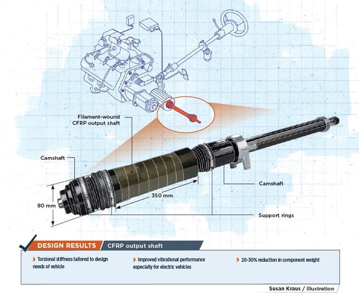
Design optimization using the parameters that Senger’s team specified resulted in an output shaft 350 millimeters long with an 80-millimeter diameter. The steel shaft, which is solid, has a smaller diameter than the hollow, tubular CFRP shaft, but sufficient space is available to accommodate the larger CFRP shaft.
Joining technology. A combination of an outer CFRP support ring and an inner “press-fit connector” on each end of the output shaft ensures sufficient joint pressure for needed torque transmission from the drivetrain to the vehicle’s wheel. Source | Dynexa
Also critical to shaft design is how it connects to other — usually metal — components in the drivetrain. “You need to know which forces to account for, how to design the shaft, how to prepare the metal and how to assemble it,” Schwarz says. A metal output shaft transmits torque via a welded connection between the shaft and other metal components. With the CFRP shaft, on the other hand, the connection is made with a press-fit joint, in which a metal part is inserted into the CFRP tube. The metal part’s outside diameter is slightly larger than the CFRP tube’s inner diameter, creating joint pressure necessary for torque transmission. No adhesive is used. Dynexa supports its CFRP-to-metal joint with outer CFRP support rings and an inner, specially designed press-fit connector. Schwarz explains that the latter, a Dynexa technology proven over 20 years, provides torque transmission through a combination of the friction generated by joint pressure and positive locking created by micro-teeth (serration) on the metal part. Galvanic corrosion is minimized by means of a gap seal between the CFRP tube and the metal part. Dynexa’s press-fit technology “combines lightweight design with high torsional performance, both under static loads and over long periods of time under fatigue loads,” Bruckhoff states.
Compared to the steel output shaft assembly, the CFRP version is 20% to 30% lighter. Weight savings include both the lighter shaft (despite the added weight of the outer support rings, which are not part of the metal-to-metal joint) and the elimination of vibration absorbers required for the metallic version. Though the actual weight savings is not of significant value for gas-powered vehicles, it could be helpful in electric vehicles, which may achieve greater driving range even with small weight reductions.
Identifying potential value
Testing of the CFRP shaft with low torsional stiffness ended up demonstrating how important torsional stiffness is to power hop reduction. Matching the lower torsional stiffness of the steel shaft, the prototype CFRP output shaft did not improve power hop performance, Senger reports. “Driving tests show that the power hop of the vehicle has the same intensity with the CFRP shafts as when the steel shafts are installed.”
The study suggests that, for gas-power vehicles that need lower torsional stiffness in the output shaft, successful reduction in power hop would require modifications to tube geometry. “In order to achieve further added value, the use of a longer CFRP tube is necessary,” Bruckhoff concludes. “The reduction of the outer diameter is also desirable for the entry into large series vehicles with composite standard components.”
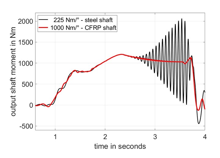
Torsional stiffness makes the difference. A simulation using Matlab Simulink suggests that a CFRP output shaft with high torsional stiffness may eliminate the power hop phenomenon. The driving maneuver simulated is acceleration of a front wheel-drive, gas-powered vehicle from a standstill on a wet and even road surface. Though gas-powered vehicles may be better served by lower torsional stiffness for other driving performance issues, electric-powered vehicles are strong candidates for further development of the CFRP output shaft. Source | Linda Senger
In electric cars, however, Senger believes that the key to success for CFRP output shafts is the high torsional stiffness that CFRP is able to provide. “High stiffness creates a more direct responsiveness of the vehicle, and thus improves the driving dynamics,” she says. Electrified powertrains can employ shafts with high torsional stiffness because they do not experience the same non-uniformity of the crank shaft found in gas-powered vehicles. It is the gas engine’s combustion process and the resulting forces on the crank shaft that creates the non-uniformity, and electric power does not generate these same forces.
A stiffer output shaft increases the powertrain’s torsional natural frequency (the frequency at which an operational vibration causes the component to resonate and amplify that vibration.). “The vibration mode of a shaft with high torsional stiffness causes much lower loads to all components that are excited by the power hop phenomenon,” Senger points out. A simulation has shown that, under the same driving conditions, a CFRP output shaft with high torsional stiffness will eliminate the power hop experienced by a metal shaft with low torsional stiffness.
Moving forward
Reflecting on the output shaft work so far, Bruckhoff says, “The CFRP output shaft product group creates new added value in terms of driving characteristics and comfort. Together with our partners, we will work out these advantages and realize a product optimized in terms of requirements and price.”
More studies of potential CFRP output shaft applications have not yet been announced by the OEM but seem likely. As for the Dynexa team, this predevelopment project has provided new insights into CFRP applications; in particular, vehicle tests validate theoretical assumptions and continually improve design competence. “It is important that we keep at it and continue to develop this product group together with our OEM partners,” Bruckhoff maintains. “Our goal is to transfer successful developments step by step into a series application.”


.jpg;maxWidth=300;quality=90;format=webp)
Related Content

XlynX Materials introduces PFAS-free BondLynx molecular adhesive
Improved version of BondLynx eliminates fluorine for a more sustainable adhesive option, while still outperforming conventional adhesive bonding strength.
Read More
XlynX Materials BondLynx and PlastiLynx for low surface energy PP, PE substrates
Award-winning Xlynx materials use breakthrough “diazirine” technology to boost bond strength up to 950% as adhesives, primers and textile strengtheners.
Read More
PE adhesive creates strong, fast bonds to low surface energy substrates
CAMX 2023: IPS Adhesive’s Scigrip brand introduces SG400LSE, a transluscent, low-color adhesive that has proven its ability to bond to FRPS, metals, plastics and other polymers.
Read More
Scott Bader, Oxeco partner for high-performance bonding solution
Joint technology breaks barriers to bonding lightweight flexible solar panels to roofing structures made from aluminum, coated steel and composites.
Read MoreRead Next

From the CW Archives: The tale of the thermoplastic cryotank
In 2006, guest columnist Bob Hartunian related the story of his efforts two decades prior, while at McDonnell Douglas, to develop a thermoplastic composite crytank for hydrogen storage. He learned a lot of lessons.
Read More
Composites end markets: Energy (2024)
Composites are used widely in oil/gas, wind and other renewable energy applications. Despite market challenges, growth potential and innovation for composites continue.
Read More
CW’s 2024 Top Shops survey offers new approach to benchmarking
Respondents that complete the survey by April 30, 2024, have the chance to be recognized as an honoree.
Read More