
The Combined Loading Compression (CLC) test method
Dr. Don Adams discusses the relative merits of the ASTM-adopted combined loading compression (CLC) test method.
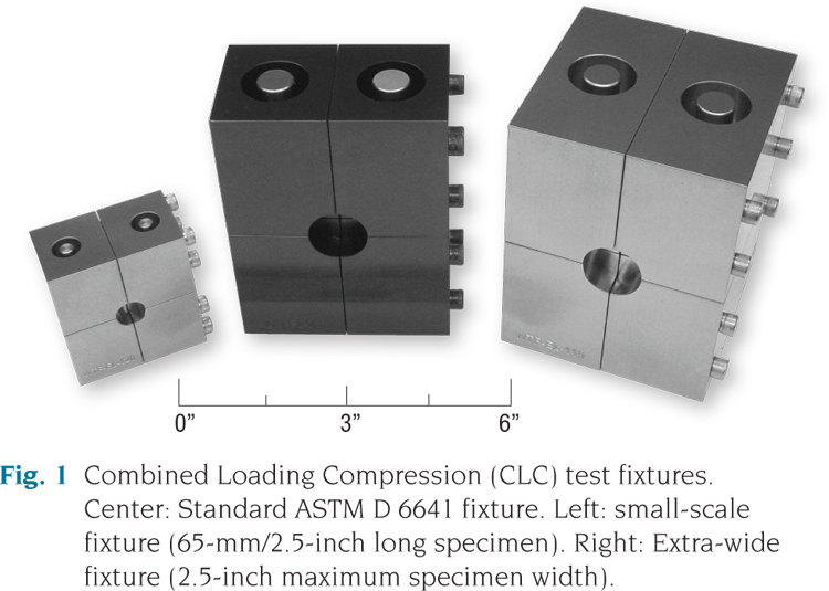
Fig. 1: Combined Loading Compression (CLC) test fixtures. Center: Standard ASTM D 6641 fixture. Left: small-scale fixture (65-mm/2.5-inch long specimen). Right: Extra-wide fixture (2.5- inch maximum specimen width). Source: Don Adams
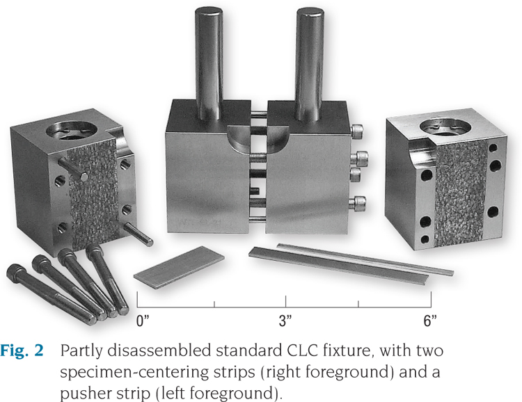
Fig. 2: Partly disassembled standard CLC fixture, with two specimen-centering strips (right foreground) and a pusher strip (left foreground). Source: Don Adams


The Combined Loading Compression (CLC) test method was standardized by ASTM in 2001, as ASTM D66411. During the past 10 years it has become the most-used compression test method for composite materials. The principal reasons for its popularity are the efficiency of load introduction into the specimen and the simplicity and ease of use of the test fixture.
ASTM standardized the fixture size and configuration shown at the center of Fig. 1, flanked by two nonstandard-size fixtures. The standard fixture accommodates a specimen 140-mm/5.5-inches long with a gage section length of 13 mm/0.5 inch. Although the standard fixture will accommodate a specimen up to 30-mm/1.2-inches wide, a 13-mm/0.5-inch specimen width is most common. This specimen’s overall length, gage length and width are the same as those typically used with the ASTM D3410 compression test method2 and represent a practical compression specimen size.


The CLC fixture is relatively simple: four steel blocks fastened together in pairs. Thus, it is easy to scale up or down, as suggested in Fig. 1. A potential concern when wider specimens are used is the difficulty of maintaining uniform loading across the specimen’s width. However, fixtures able to accommodate specimen widths up to 125 mm/5 inches have been used successfully, as have fixtures for testing shorter 65-mm/2.5-inch long specimens, as shown in Fig. 1.
A partially disassembled standard CLC fixture is shown in Fig. 2. In use, each end of the specimen is installed flush with the outer surface of the fixture block and then clamped between the pairs of blocks by tightening the four screws. Thus, when the assembly is loaded between flat platens, the specimen and the fixture blocks each carry a portion of the total applied force. However, the force applied to the fixture blocks eventually must be transferred to the specimen’s central gage section via shear forces at the fixture/specimen interface. In Fig. 2, the fixture surfaces that grip the specimen ends are coated with tungsten carbide particles, greatly increasing the effective coefficient of friction. Because shear force is equal to the coefficient of friction times the clamping force, relatively little clamping force is required.
This combination of end loading and shear loading is the main advantage of the test method. The goal is to induce just enough shear loading so the end loading does not crush the specimen ends. In practice, as little as 2.5 to 3.0 N-m (20 to 25 in-lb) of torque per screw can achieve the required clamping force. To put this in perspective, finger-tight torque on a screw is about 1.25 N-m/10 in-lb. Relatively low clamping forces keep the undesirable through-the-thickness compressive stresses to a minimum.
Originally, ASTM D6641 was written for testing of untabbed specimens. This is possible if the composite strength is not too high. The combined loading reduces the end loading sufficiently to avoid crushing the ends of the untabbed composite. The test of an untabbed [90/0]ns composite laminate is particularly attractive because it is relatively straightforward; classical lamination theory can be used to back out the 0° ply strength. (For a discussion of this back-out technique, see “Back-out factors" under "Editor's Picks," at top right.)
In 2009, ASTM D6641 was revised to include tabbed composites, permitting the use of the CLC method on high-strength materials, such as unidirectional [0]ns composites. No existing compression test method can be used successfully to test untabbed specimens of such strong materials, and the CLC test method is no exception. Tabs must be used. However, the CLC test method’s ability to combine end and shear loading, as opposed to pure end loading or pure shear loading, is a gentler method for introducing stress into the gage section, and as a result, it yields more uniform test results with less data scatter.
Tabs serve different purposes for the different types of loading. On CLC specimens, they shift to the tab ends some of the applied end load that would otherwise be carried entirely by the composite. Thus, a greater overall load can be applied without end crushing. The total applied load is actually apportioned in three ways: 1) to the ends of the composite; 2) to the ends of the tabs; and 3) to the fixture blocks. The load-sharing ratios can be controlled by adjusting the tab stiffness and thickness and the torque on the fixture screws. As with untabbed composites, the goal is to reduce the end loading on the composite enough to prevent end crush before the specimen fails in the gage section.
The adhesive used to bond the tabs to the specimen must be strong enough to transfer the end loads on the tabs and fixture blocks into the specimen via shear. Yet even when a high-strength unidirectional composite, such as glass/epoxy or carbon/epoxy, is tested, the CLC method can use tabbing materials and adhesives common to tabbing procedures in other test regimes. For example, for typical specimen thicknesses — in the range of 2 to 2.5 mm (0.08 to 0.10 inch) — a typical tabbing material is a glass fabric/epoxy laminate, such as a 1.6-mm/0.06-inch thick G-10 printed circuit board, as discussed in my March 2011 column (see “Tabbing composite test specimens: When and why” under "Editor's Picks").
The CLC test method, assuming that the current increasing rate of use continues, should eventually replace the various shear-loading and end-loading compression test methods.
References
¹ASTM Standard D6641-09, “Compressive Properties of Polymer Matrix Composite Materials Using a Combined Loading Compression (CLC) Test Fixture,” ASTM International (W. Conshohocken, Pa.), 2009 (first issued in 2001).
²ASTM Standard D3410-03 (2008), “Compressive Properties of Polymer Matrix Composite Materials with Unsupported Gage Section by Shear Loading,” ASTM International (W. Conshohocken, Pa.), 2008 (first issued in 1975).


Related Content

Kaneka BMI material attains >25% lead time, >20% tool cost reductions in Janicki evaluations
Process evaluations find that novel BMI polymer chemistry addresses longstanding manufacturing challenges of BMI tooling prepregs while maintaining high temperature performance and durability.
Read More
Testing to support composite bolted joint analysis
An overview of ASTM Standard Guide D8509, and its coupon-level mechanical testing of design properties for analyzing composite bolted joints.
Read More
Cutting 100 pounds, certification time for the X-59 nose cone
Swift Engineering used HyperX software to remove 100 pounds from 38-foot graphite/epoxy cored nose cone for X-59 supersonic aircraft.
Read More
Bladder-assisted compression molding derivative produces complex, autoclave-quality automotive parts
HP Composites’ AirPower technology enables high-rate CFRP roof production with 50% energy savings for the Maserati MC20.
Read MoreRead Next

Tabbing composite test specimens: When and why
Dr. Don Adams (Wyoming Test Fixtures Inc., Salt Lake City, Utah) discusses when and why test specimens must be protected by tabs.
Read More
Back-out factors
Dr. Adam's follows up a previous column, in which he discussed the advantages of testing a cross-ply laminate and then "backing out" the unidirectional composite strength, with an expanded examination of back-out factors that can be applied to other types of laminates.
Read More
Testing cross-ply vs. unidirectional composites
Dr. Don Adams follows up his previous column on tensile testing with a discussion of such testing when confronted by two difficult-to-test laminate configurations.
Read More