
Interlaminar tensile testing of composites: An update
New test method developments for measuring interlaminar tensile strength address difficulties associated with the ASTM D6415 curved beam flexure and ASTM D7291 flatwise tensile tests.


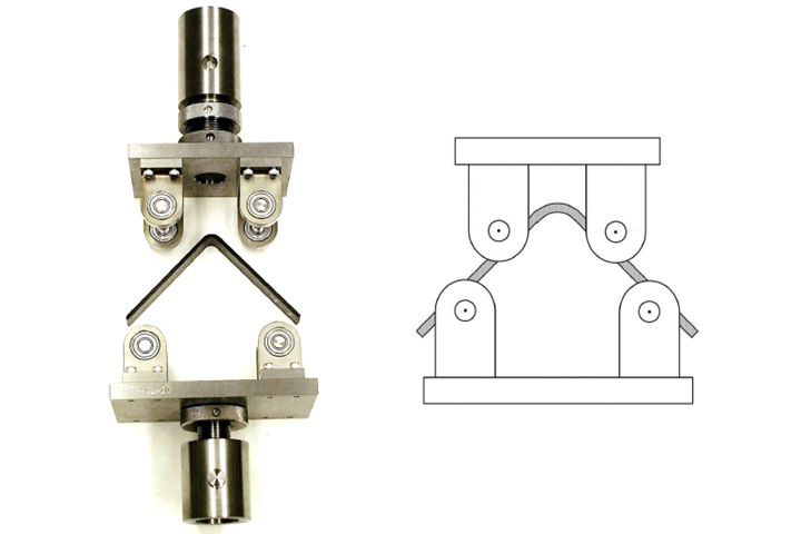
Figure 1. ASTM D6415 test fixture and curved beam specimen. Photo Credit, all images: Dan Adams
Back in April 2015, my CW column focused on the two ASTM standardized test methods used for measuring the through-the-thickness, or interlaminar, tensile strength of composite laminates. Despite their difficulties and limitations, the ASTM D64151 curved beam flexure test and the ASTM D72912 flatwise tensile test are still commonly used for measuring interlaminar tensile strength. However, neither test method is viewed as completely satisfactory.
Although less commonly measured than the in-plane tensile properties of a unidirectional (UD) composite, interlaminar tensile strength is an important material property due to its greatly reduced value in comparison to the fiber-direction in-plane tensile strength. Although it is often similar in magnitude to the in-plane transverse tensile strength, changes to the manufacturing method may affect the bond strength between plies of a composite laminate and significantly reduce the interlaminar tensile strength.


Since writing my 2015 column on the topic of interlaminar tensile testing, additional test methods have been proposed and investigated for addressing the problems associated with the two standardized test methods. In this column, I’ll provide an update on these additional test methods for measuring the interlaminar tensile strength of composites. Before doing so, however, I’ll briefly summarize the difficulties associated with the two current ASTM standardized methods, which use very different specimen geometries and loading methods.
The first test method, ASTM D6415, uses an indirect loading method to produce an interlaminar tensile stress state in the central region of a curved beam specimen. As shown in Fig. 1, the specimen is composed of two straight “legs” connected by a central curved region to produce a 90° bend. The specimen is loaded in four-point flexure using the specialized test fixture also shown. Flexural loading of the curved beam specimen results in an opening of the 90° angle and produces a region of through-the-thickness, or interlaminar tensile stress, in the central curved region of the specimen. Although the curved beam flexure test is simple to perform, the fabrication of the curved beam specimens is often problematic, as ply waviness and porosity are commonly produced in the curved region, significantly reducing the measured interlaminar tensile strength.
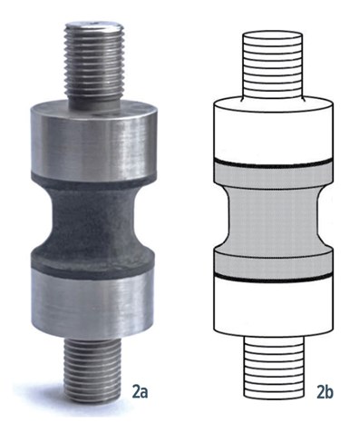
Figure 2. ASTM D7291 interlaminar test specimen.
A second interlaminar tensile test method for composites, the ASTM D7291 flatwise tensile test, produces interlaminar tensile stress through direct out-of-plane tensile loading of a cylindrical composite specimen as shown in Fig. 2. Steel fixture blocks are bonded to the top and bottom of the composite specimen for use in load application. When using specimen thicknesses of 25 millimeters or greater, the standard recommends a tapered specimen diameter in the central region to produce a reduced-area test section and promote failure away from the bonded end blocks. While simple in concept, the specimen and fixture block assembly is prone to misalignment during the bonding operation, leading to high levels of variability in test results. The test standard details an elaborate bonding fixture for maintaining alignment while bonding the fixture blocks to the cylindrical composite test specimen.
A more recent development has been the use of a short beam flexure test to measure interlaminar tensile strength. This test methodology uses the same three-point flexure loading configuration used in the ASTM D23443 short beam shear test. In both test methods, three-point flexure loading produces peak bending stresses (compression and tension) in the upper and lower regions of the specimen. Additionally, the maximum shear stress is produced in the mid-thickness region of the specimen. In fact, the only significant difference between the short beam shear and short beam flexure tests is the fiber orientation within the short beam specimen that’s being tested. Whereas the fibers are oriented along the specimen length in short beam shear specimens (Fig. 3a), they are oriented perpendicular to the specimen length in short beam flexure specimens as shown in Fig. 3b. This difference in fiber orientation within the two types of specimens results in different failure modes occurring in the two types of short beam tests; interlaminar shear failure is produced in the short beam shear tests and transverse tensile failure in the short beam flexure tests.
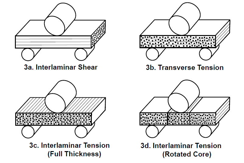
Figure 3. Short beam flexure testing configurations.
As illustrated in Fig. 3b and 3c, two different ply orientations are possible when performing short beam flexure testing, allowing two different tensile strength properties to be measured. When the ply interfaces are oriented horizontally as shown in Fig 3b, the test becomes a transverse tensile test and provides a measure of the transverse tensile strength. However, when the ply interfaces within the specimen are oriented vertically (Fig. 3c), the test becomes an interlaminar tensile test — the subject of this column — and provides a measure of the interlaminar tensile strength. Thus, the flexure-based interlaminar tensile test shown in Fig. 3c may be viewed as an alternative to the two standardized test methods shown in Fig. 1 and Fig. 2.
A significant disadvantage of the flexure-based interlaminar tensile specimen shown in Fig. 3c for measuring the interlaminar tensile strength is that it requires extremely thick UD laminates to be manufactured, from which short beam flexure specimens are oriented in the through-thickness direction as shown in Fig. 3c. Makeev et al.4 reported using 100-200 ply UD laminates for such specimens, depending on the ply thickness of the composite material. The use of such thick laminates is often problematic due to difficulties with debulking and material consolidation during cure, resulting in voids and other defects.
To address these concerns, Fisher and Czabaj5 developed a three-piece bonded specimen design using standard-thickness UD laminates as shown in Fig. 3d. The test panels were produced by cutting out and replacing the central region of the panel with an equal-sized panel section that is rotated 90° from the original orientation, such that the ply boundaries extend through the specimen thickness. The three pieces of the test panel were bonded together using a paste adhesive and cut into the “rotated core” specimen configuration shown in Fig. 3d. Thus, when subjected to three-point flexure loading, an interlaminar tensile stress state is produced in the central “rotated core” section of the specimen. Using this configuration, the UD laminate was reduced to a manageable thickness and the associated manufacturing problems were minimized.
Having summarized these test methods for measuring interlaminar tensile strength, the question arises of whether this quantity is a true “material property,” such that one should expect similar results from any of the aforementioned test methods. Currently, the general consensus is that interlaminar tensile strength values vary with specimen configuration and the resulting volume of material that is being tested. Additionally, differences in the manufacturing method used for each type of test specimen (different shape, size, thickness, etc.) can affect the bond strength between plies of the composite laminate and therefore affect the measured strength values. As a result, the measured interlaminar tensile strengths should be considered a “structural property,” which is dependent on the specimen configuration and manufacturing method used, rather than a true “material property.”
References
1ASTM D6415/D6415M-22, “Standard Test Method for Measuring the Curved Beam Strength of a Fiber-Reinforced Polymer-Matrix Composite,” ASTM International (W. Conshohocken, PA, US), 2022 (first issued in 1999).
2ASTM D7291/D7291M-22, “Standard Test Method for Through-Thickness ‘Flatwise’ Tensile Strength and Elastic Modulus of a Fiber-Reinforced Polymer Matrix Composite Material,” ASTM International (W. Conshohocken, PA, US), 2022 (first issued in 2007).
3ASTM D2344/D2344M-22, “Standard Test Method for Short-Beam Strength of Polymer Matrix Composite Materials and Their Laminates,” ASTM International (W. Conshohocken, PA, US), 2022 (first issued in 1965).
4Makeev, A., Guillaume, S., Nikishkov, Y., and Lee, E., “Methods for Assessment of Interlaminar Tensile Strength of Composite Materials,” Journal of Composite Materials, Vol 49, 2015, pp. 783-794.
5Fisher, J. and Czabaj, M., “A New Test for Characterization of Interlaminar Tensile Strength of Tape-Laminate Composites,” Proceedings of the 2023 American Society for Composites Technical Conference, Boston, MA, Sept. 17-20, 2023.


.jpg;maxWidth=300;quality=90;format=webp)


Related Content

Material equivalence testing in shared composites databases
In response to traditionally proprietary polymer matrix composites (PMC) qualifications, NCAMP continues its efforts to make material property databases publicly available.
Read More
Composite test methods (and specifications) for fiber-reinforced concrete structures
While initially focused on transitioning existing standards published by the American Concrete Institute, the relatively new ASTM Subcommittee D30.10 is developing new standardized test methods and material specifications for FRP composites.
Read More
Improving analyses of composite pressure vessels
Accurate geometry modeling and equivalent material property approximations captured by WoundSim will play a role in improving COPV analyses.
Read More
Notched testing of sandwich composites: The sandwich open-hole compression test
A new ASTM-standardized open-hole compression test method seeks to determine the notch sensitivity of sandwich composites.
Read MoreRead Next

What’s the most important type of mechanical test for composites?
When the opportunity arises, I like to ask those familiar with composites testing this question: What type of mechanical test do they consider to be the most important for composite materials?
Read More
Choosing composite material testing methods
An initial step in selecting suitable test methods involves consulting the available test literature.
Read More
Composite test methods (and specifications) for fiber-reinforced concrete structures
While initially focused on transitioning existing standards published by the American Concrete Institute, the relatively new ASTM Subcommittee D30.10 is developing new standardized test methods and material specifications for FRP composites.
Read More