
Methods for interlaminar tensile testing of composites: A comparative evaluation
Dr. Daniel O. Adams, professor of mechanical engineering and director of the Composite Mechanics Laboratory at the University of Utah and VP of Wyoming Test Fixtures Inc. (Salt Lake City, UT, US) compares and contrasts the direct and indirect loading methods for interlaminar tensile testing of composites.

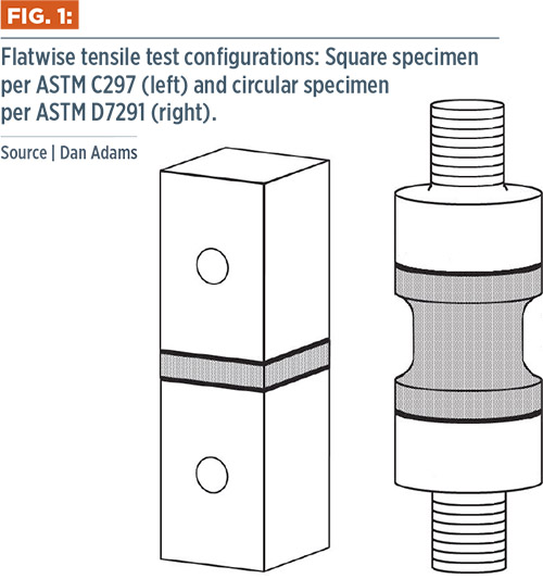
Fig. 1: Flatwise tensile test configurations: Square specimen per ASTM C297 (left) and circular specimen per ASTM D7291 (right). Source: Dan Adams
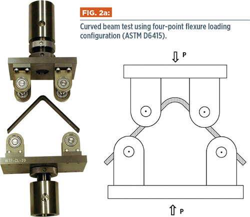
Fig 2a: Curved beam test using four-point flexure loading configuration (ASTM D6415). Source: Dan Adams
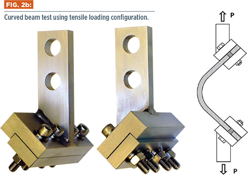
Fig 2b: Curved beam test using tensile loading configuration. Source: Dan Adams


As the name suggests, interlaminar tensile testing is performed to measure tensile properties in the through-thickness direction of composite laminates rather than the more commonly measured in-plane properties. Although the out-of-plane tensile modulus, E3, and Poisson’s ratios, ν31 and ν32, can be obtained, the interlaminar tensile strength is of greatest interest. It’s common to assume that E3 is equal to the in-plane transverse tensile modulus, E2, making its measurement of lesser importance. This is not the case, however, for the interlaminar tensile strength. Differences in manufacturing methods can affect the bond strength between the plies of a composite laminate and produce significant differences between the interlaminar tensile strength and the in-plane tensile strength transverse to the fiber direction. Therefore, this column will focus on test methods available for measuring this interlaminar tensile strength property in composites.
Fiber-reinforced composite structures are designed with fibers positioned to carry tensile loads in desired in-plane orientations, so why is interlaminar tensile strength of such interest? One reason is because the interlaminar tensile strength can be two orders of magnitude less than the in-plane tensile strength in the fiber direction. As a result, relatively small interlaminar tensile stresses can lead to disbond failure between composite plies. This strength property also is used in progressive damage modeling of composites for predicting the formation of delaminations in composite structures. Finally, as mentioned above, the interlaminar tensile strength is used to assess whether an as-manufactured composite has acceptable bond strength between the plies.


There are two general methods in use for interlaminar tensile testing of composites, the direct and indirect loading methods. The former produces interlaminar tensile stress by directly applying an out-of-plane tensile load to a flat composite specimen. In practice, metal fixture blocks typically are bonded to the top and bottom surfaces of the composite specimen and used for load application (Fig. 1, at left). This method, the flatwise tensile test, is described in two ASTM standards that differ significantly. ASTM C2971 features square specimens and is intended primarily for sandwich composites. ASTM D72912 is a more recent standard that specifies circular specimens and focuses on maintaining alignment while bonding the fixture blocks to the specimen. Because the state of stress is not affected significantly by the cross-sectional shape of the specimen, the choice between square and circular specimens often is based on machining and fixturing preferences. In contrast, indirect loading methods generate interlaminar tensile stresses by applying bending moments to curved beam specimens. The most common is the four-point bend loading configuration specified in ASTM D64153 (Fig. 2a, at left). However, the required bending moment also can be produced by clamping the specimen legs in special fixtures and loading in tension (Fig. 2b, at left). In both cases, interlaminar tensile stresses are produced only in the specimen’s central curved portion.
So which interlaminar tension test is best? Unfortunately, there’s no simple answer, because both methods have shortcomings. One can select the method best suited for a particular situation only with a good understanding of their relative advantages and disadvantages. One important consideration is the restrictions that each method places on the test panel used. This may appear to favor the direct-loaded, flatwise tensile test, because specimens may be obtained from a flat composite laminate. However, a bobbin-shaped specimen (Fig. 1, image at right) is often needed to produce acceptable failures away from the bonded fixture blocks. As a result, a relatively thick test panel (25 mm or more) is suggested to produce these tapered cross section specimens.
For the indirect-loaded specimens, the central curved region where interlaminar tensile stresses are produced is often the site of manufacturing problems, such as layer waviness, resin-rich regions and voids. As such, it is questionable whether this test region is representative of a flat laminate. Another restriction that is sometimes overlooked: The curved beam specimen should be fabricated as a unidirectional laminate, with the fibers oriented along the curved beam’s length. The reason? The equation used to calculate interlaminar tensile strength comes from an anisotropic elasticity solution that is valid only for a unidirectional composite laminate. For multidirectional laminates, the less meaningful curved beam strength (maximum bending moment per unit width) is obtained. A detailed numerical analysis of the multidirectional test specimen is needed to determine the interlaminar shear strength from these specimens. These restrictions associated with the curved beam specimen make the thick flat panel for flatwise tensile testing more desirable.
Before choosing the direct-loaded flatwise tensile test method, however, another important consideration is the procedures required for preparing and testing the specimens from the test panel. For curved beam testing, specimens may be sliced from the curved panel using relatively simple machining procedures. Performing the curved beam test under four-point flexure loading is relatively straightforward as well. For flatwise tensile testing, however, considerably more effort is required in preparing the specimens. After machining specimens from the test panel, their top and bottom surfaces are prepared for adhesive bonding to the metal fixture blocks. Maintaining alignment is critical when bonding the specimens to the loading blocks and during testing. ASTM D 7291 describes an elaborate bonding jig that may be used to align circular specimens during bonding; however, simpler methods are possible as well. Lack of alignment produces bending in addition to tensile loading, resulting in a nonuniform stress state and reductions in the measured interlaminar tensile strength. After bonding, the cross section of the circular specimens is machined to produce the desired bobbin shape. Note that these operations require more time and cost than the curved-beam test.
A final consideration concerns the values of interlaminar tensile strength: Should the user expect the two methods to yield comparable results? Not necessarily, because there are some important differences in the specimen stress states as well as the volume of material being tested. With proper alignment, the direct-loaded, flatwise tensile test produces a relatively uniform state of interlaminar tensile stress in the reduced-area test section of the specimen. This favorable stress state is present over a sufficiently large volume of material. In contrast, the indirect-loaded curved beam specimen that’s subjected to four-point flexure loading experiences a combined stress state in the curved central region that includes undesirable in-plane tension and compression stresses due to the applied bending moment. These in-plane stresses can be an order of magnitude larger than the intended interlaminar tensile stresses. Additionally, the volume of material in the region of high interlaminar tensile stress is smaller than in the flatwise tensile test.
In general, both methods are known for producing large amounts of scatter in the test results. In the flatwise tensile test, scatter is often attributed to improper alignment, which causes bending stresses in the specimen. For the curved beam test, scatter is typically attributed to manufacturing problems in the central curved portion of the specimen.
There are difficulties and limitations associated with the direct and indirect test methods for interlaminar tensile strength measurement. Both are standardized and in common use, but neither is viewed as completely satisfactory. By understanding their relative advantages and disadvantages, however, users can chose the method that best fits their application.
References
1ASTM C 297-04, “Flatwise Tensile Strength of Sandwich Constructions,” ASTM International (W. Conshohocken, Pa.) first issued in 1952.
2ASTM D 7291-07, “Through-Thickness ‘Flatwise’ Tensile Strength and Elastic Modulus of a Fiber-Reinforced Polymer Matrix Composite Material,” ASTM International (W. Conshohocken, Pa.), first issued in 2007.
3ASTM D 6415-06, “Test Method for Measuring the Curved Beam Strength of a Fiber-Reinforced Polymer-Matrix Composite,” ASTM International (W. Conshohocken, Pa.), first issued in 1999.


.jpg;maxWidth=300;quality=90;format=webp)


Related Content

Scott Bader ATC begins Crestabond MMA structural adhesive production
Scott Bader’s Drummondville, Canada, facility has begun manufacturing and supplying composites-applicable adhesives to its North American customers.
Read More
Materials & Processes: Resin matrices for composites
The matrix binds the fiber reinforcement, gives the composite component its shape and determines its surface quality. A composite matrix may be a polymer, ceramic, metal or carbon. Here’s a guide to selection.
Read More
XlynX Materials BondLynx and PlastiLynx for low surface energy PP, PE substrates
Award-winning Xlynx materials use breakthrough “diazirine” technology to boost bond strength up to 950% as adhesives, primers and textile strengtheners.
Read More
CAMX 2022 exhibit preview: Conductive Composites
Conductive Composites expands its portfolio of multifunctional electrically conductive composite materials with a new line of NiShield nonwovens and NiBond electrically conductive two-part structural epoxy adhesive.
Read MoreRead Next

CW’s 2024 Top Shops survey offers new approach to benchmarking
Respondents that complete the survey by April 30, 2024, have the chance to be recognized as an honoree.
Read More
Composites end markets: Energy (2024)
Composites are used widely in oil/gas, wind and other renewable energy applications. Despite market challenges, growth potential and innovation for composites continue.
Read More
From the CW Archives: The tale of the thermoplastic cryotank
In 2006, guest columnist Bob Hartunian related the story of his efforts two decades prior, while at McDonnell Douglas, to develop a thermoplastic composite crytank for hydrogen storage. He learned a lot of lessons.
Read More