
How is tow spread?
ITA characterizes tow spreading processes and parameters as it develops new technology to speed production (100 m/min) and reduce width variation (<1mm).


As the feature article “The spread of spread tow” went to print, this Side Story was much different, talking mostly about how much we don’t know about how tow is spread. And then I ran across an article in the AZL newsletter NewsLIGHT #7: ITA titled “New ultrasonic spreading process for processing reinforcement tows”. It turns out that the Institute for Textile Technology (ITA) at RWTH Aachen University (Aachen, Germany) has been studying spread tow methods since 2011. “We began testing all of the various methods for spreading tow into tape and did a lot of research on the influencing factors of each and how to optimize these,” says Wilko Happach, head of the Tapes research group within ITA’s Composites Division. As a result, ITA has developed new technology enabling high-speed production — up to 100 m/min — of spread tow tape with much less variation in width thanks to integrated control. ITA calls this technology AutoTow.
Understanding spread tow techniques
ITA began its research in pursuit of tape. “We had seen that woven and noncrimp fabrics produced significant cutting waste and also did not allow for optimized designs,” Happach recalls. “Because the fibers are not all applied in the direction of the loads, fiber is wasted.” Thus, his team began looking at automated tape laying, but there was both a lack of tape supply and knowledge at that time, says Happach. “So we made our own, choosing to develop dry-fiber, bindered tapes first.” To do this, however, they first had to understand spreading.


Happach describes three basic methods for spreading roving into wider, thinner tapes:
- Pulling fibers over spreader bars using high tension.
- Air spreading using a slit nozzle.
- Applying ultrasonic or other vibration to fibers.
Spreading Technologies and Process Parameters

|

Air spreading
|
 |
|
|
|
SOURCE: ITA Tape Center, RWTH Aachen University.
Spreader bars appear to be the oldest and most basic technique, used in a 2001 patent filed by carbon fiber producer Zoltek. Happach notes that equipment supplier Karl Mayer has also relied on spreader bars in its tape and spread tow fabric machines. “The problem with this method is that it limits production speed to 25 m/min,” he says. “If you try to go higher, the friction is too high and damages the roving filaments. Bar spreading is also limited in the maximum spreading width. You can spread roving to 3 times its initial width at most.”
Air spreading, says Happach, is used when maximum spreading width is desired for lower areal weight. “The air flow separates the filaments and enables spreading up to 6-7 times the initial roving width with much lower filament damage because there is less friction,” he explains. “There is no pulling the fiber over bars at high tension.”
However, there is a limitation depending on the size applied to the glass or carbon fiber. Happach explains, “Fiber sized for epoxy and other thermoset resins can be sticky, so that the air spreading process cannot separate the filaments easily.” In this case, a pre-process may be needed to break up the size a bit. However, size compatible with thermoplastic matrix resins, which is also thermoplastic, is not sticky at all and acts almost like an unsized fiber. In other words, there is no interfilament adhesion. “So this is easy to spread but difficult to handle because it tends to fall apart,” notes Happach.
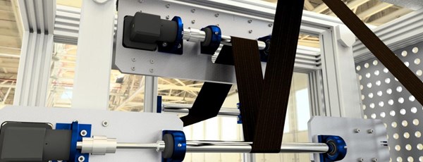
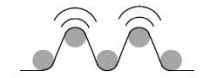
Ultrasonic spreading uses the same basic principle as spreader bars but with half-cylinder shaped sonotrodes, which, Happach notes, “convey a great deal of energy. The roving wraps around the sonotrodes and by applying ultrasound, the filaments vibrate and settle down onto the surface, spreading out.” This technique can yield higher spreading ratios (i.e., larger fiber tow spread into very thin, wide tapes) but cannot be used with glass fiber or pitch-based carbon fiber because they are too brittle and will break.
“You can also use mechanically induced, lower frequency vibration,” says Happach, “and heat can be used to soften the fiber size, allowing the filaments to move more readily.”
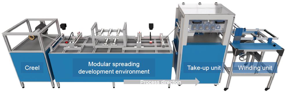
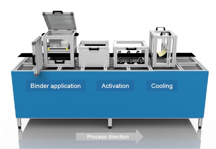
The ITA Tape Center’s tape production line (top) and binder application line (bottom) are key pieces to the roving-to-parts full process chain it is constructing in order to help industry partners find new composites technology solutions. SOURCE: ITA Tape Center, RWTH Aachen University.
AutoTow
ITA developed AutoTow to overcome the issues with these basic spreading methods. Happach notes the Tape Center works mostly with 24K, 50K and 60K tow (which he notes is from Mitsubishi) because the spreading effects are highest. “We can reach higher production speeds of up to 100 m/min because we can rotate the individual spreader bars at up to 80 m/min,” he explains. “Thus, the relative speed is 20 m/min, which is good for spreading without filament damage.”
Happach points out that because the input roving/tow has variations, the width of the output spread tow also varies. “With prepreg tapes, suppliers simply cut off the edges. But we started with dry, bindered tape, which has much less resin, so it is too hard to cut the edges.” Happach’s team realized they needed a better means to control the spreading width.
“We use cameras to measure the width going in and coming out of the spreader,” he explains. “An algorithm uses this width measurement, the process speed and certain known factors about each material to calculate and control the speed of each of the 5 rotating bars to continuously adjust the tape width. We can reduce the variation to less than 1 millimeter.”

AutoTow integrated width control using camera measurement to reduce width variation to less than 1 mm. SOURCE: ITA Tape Center, RWTH Aachen University.
“We are also able to adjust the wrapping angle of the roving around each spreading bar,” Happach continues, “but not in real-time.” So, this is more like a calibration for each production run. “Everything else is done in-line,” he contends. “If you want to go from 25 mm to 30 mm in spread tow width, just enter that number and within a few seconds it will change during production, and at high-speed, even 100 m/min.”
Future development
The goal of the ITA Tape Center is to have the full tape process chain in order to support industry development. “Our goal is to attract industry partners to develop new solutions for them,” explains Happach. “We are in the process of building a tape production line and parts production line also. We want to have all of the operations: sizing, spreading, tape production, automated tape laying and curing.” He says ITA will never be a machine supplier or parts fabricator. “We want to achieve production of lightweight thin-ply parts because we’ve seen the thinner the layers, the higher the mechanical properties. Now that we can produce dry, bindered tapes at high speeds and a high-quality level, our goal is to go lower in areal weight and next to produce thermoplastic and thermoset prepreg tapes.”
The ITA Tape Center has researched various thermoset- and thermoplastic-compatible binder technologies.
Just as the ITA Tape Center has defined the production space for spread tow processes and their parameters, it has also developed significant knowledge around the impact of fiber size and tape binder technology. “We have suppliers that want to test different size recipes to see what is best for spreading,” says Happach.
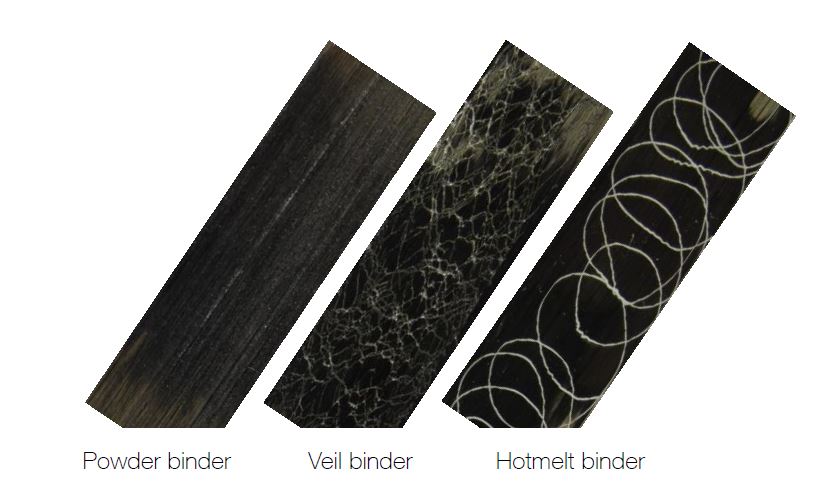
For binder materials, he stresses the most important factor is compatibility with the matrix resin. “A thermoset binder will achieve the highest properties for a thermoset matrix.” Likewise, for a thermoplastic matrix the binder should be thermoplastic, and can be applied using powder, veil or hot melt. The latter two enable very quick application and give high stability to the tape, but Happach notes the veil will give slightly higher binder content. This may or may not be desired depending on part design and fabrication process considerations. Research on binder parameters and how these affect final parts will continue as ITA builds out its full process chain.


.jpg;maxWidth=300;quality=90;format=webp)


Related Content

Materials & Processes: Composites fibers and resins
Compared to legacy materials like steel, aluminum, iron and titanium, composites are still coming of age, and only just now are being better understood by design and manufacturing engineers. However, composites’ physical properties — combined with unbeatable light weight — make them undeniably attractive.
Read More
Materials & Processes: Fibers for composites
The structural properties of composite materials are derived primarily from the fiber reinforcement. Fiber types, their manufacture, their uses and the end-market applications in which they find most use are described.
Read More
The making of carbon fiber
A look at the process by which precursor becomes carbon fiber through a careful (and mostly proprietary) manipulation of temperature and tension.
Read More
Infinite Composites: Type V tanks for space, hydrogen, automotive and more
After a decade of proving its linerless, weight-saving composite tanks with NASA and more than 30 aerospace companies, this CryoSphere pioneer is scaling for growth in commercial space and sustainable transportation on Earth.
Read MoreRead Next

The spread of spread tow
Advancing from “lighter and thinner” to boosting strength, stiffness, impact resistance and productivity, spread tow unlocks new applications and markets.
Read More
CW’s 2024 Top Shops survey offers new approach to benchmarking
Respondents that complete the survey by April 30, 2024, have the chance to be recognized as an honoree.
Read More
Composites end markets: Energy (2024)
Composites are used widely in oil/gas, wind and other renewable energy applications. Despite market challenges, growth potential and innovation for composites continue.
Read More