


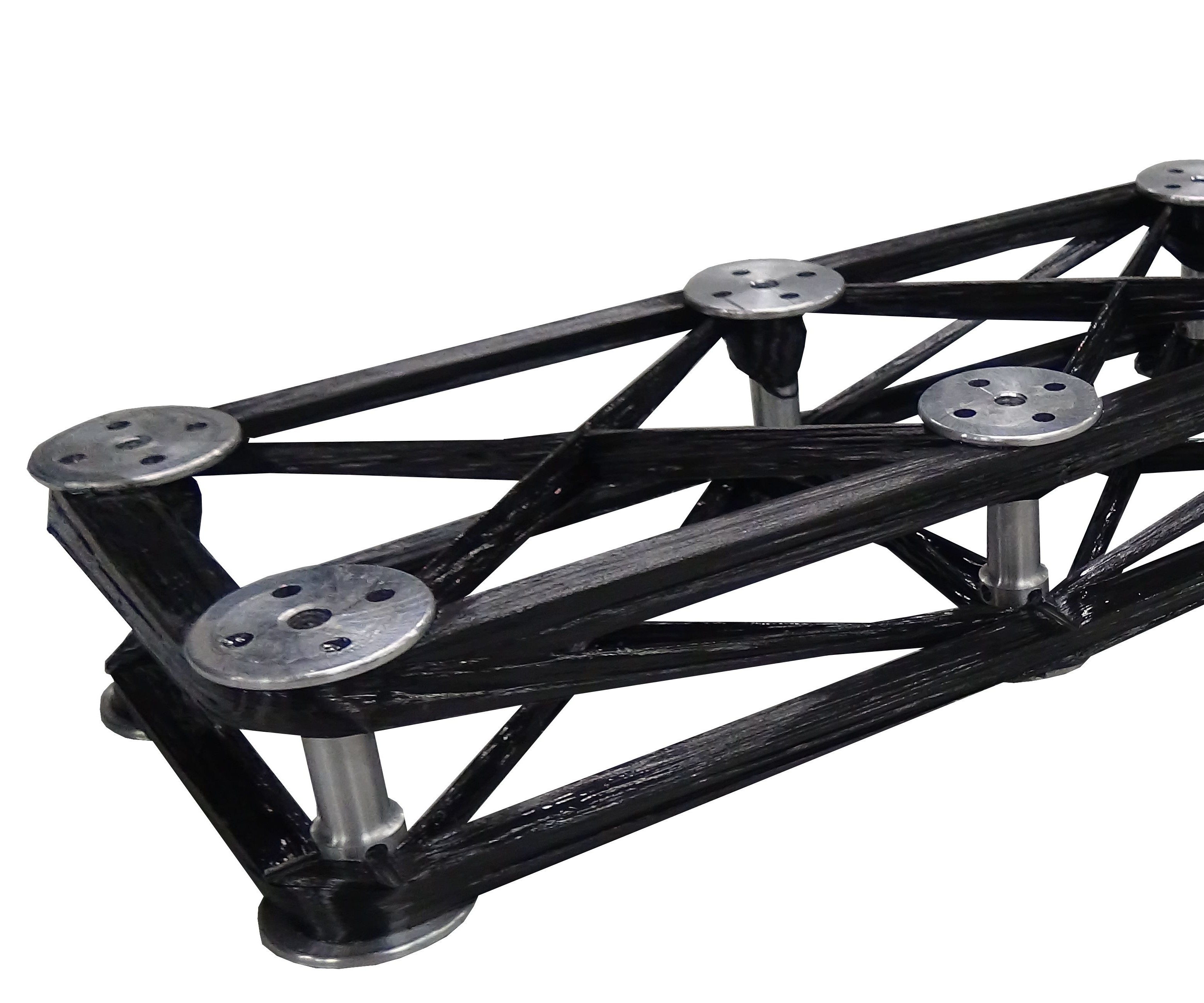
“FibreTEC 3D”
This robotic gripper for automotive assembly weighs 50% of a standard aluminum version. It is made with the FibreTEC3D process, which winds carbon fiber tow impregnated with epoxy around aluminum pins with zero waste.
Source | Daimler AG
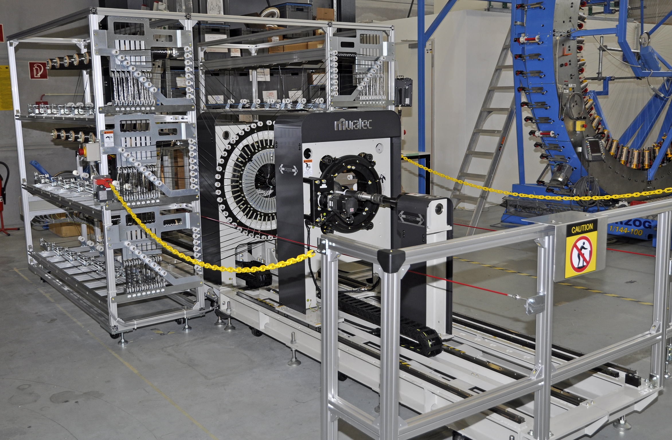
Fig. 1 Multi-filament winding touted as 50 times faster
Murata Machinery’s MFW-48-1200 simultaneously winds 48 to 180 fibers from its creel onto a rotating mandrel in the liner unit, which moves horizontally in and out of the adaptive nozzle.
Source | Murata Machinery and Institut für Textiltechnik (ITA) der RWTH Aachen
.jpg)
Fig. 2 Robot-enabled flexibility
An early adopter of robotic filament winding, MF Tech has developed an unconventional system where the rotating mandrel is manipulated past a stationary fiber feed (creel and orange and black tower at right).
Source | MF Tech/CEA
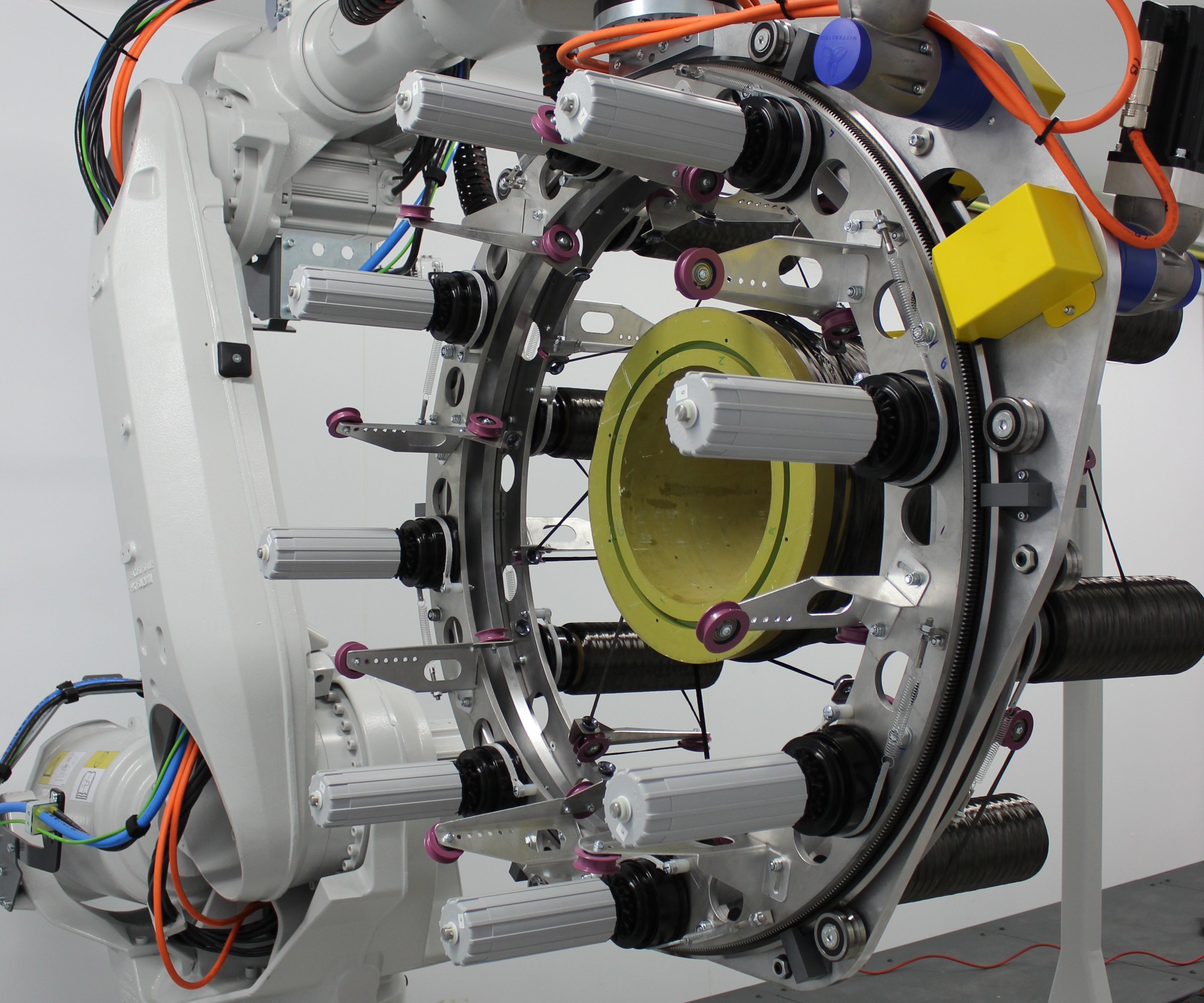
Fig. 3 Robotic 3D winding: Speed and complexity
Comprising two counter-rotating fiber application rings moved by a robot arm along the part being wound, Cygnet’s 3D winder was designed for scalable, speedy production of complex shapes, able to wind 24K or 48K carbon fiber at a rate of 1 kg/min.
Source | Cygnet Texkimp
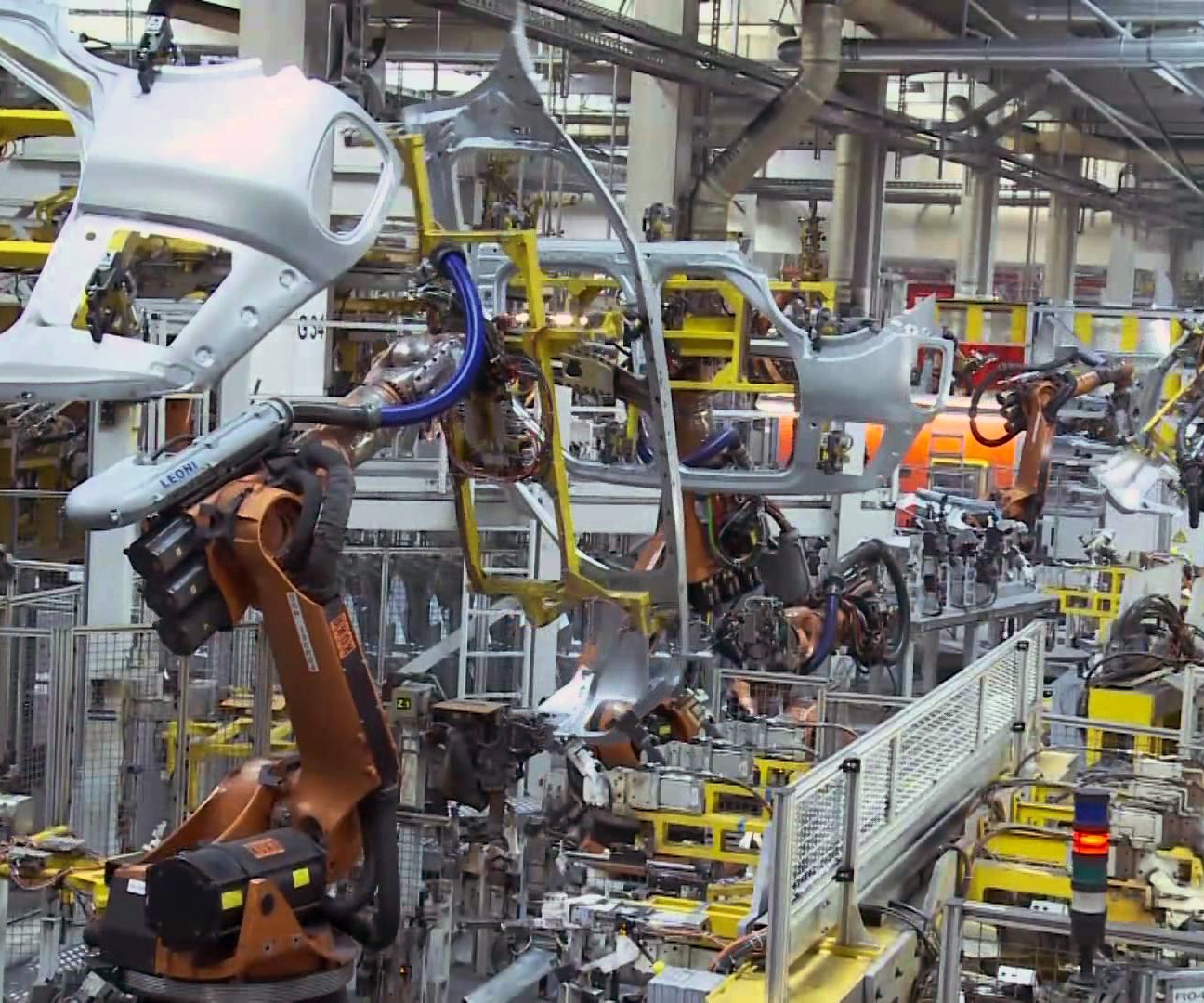
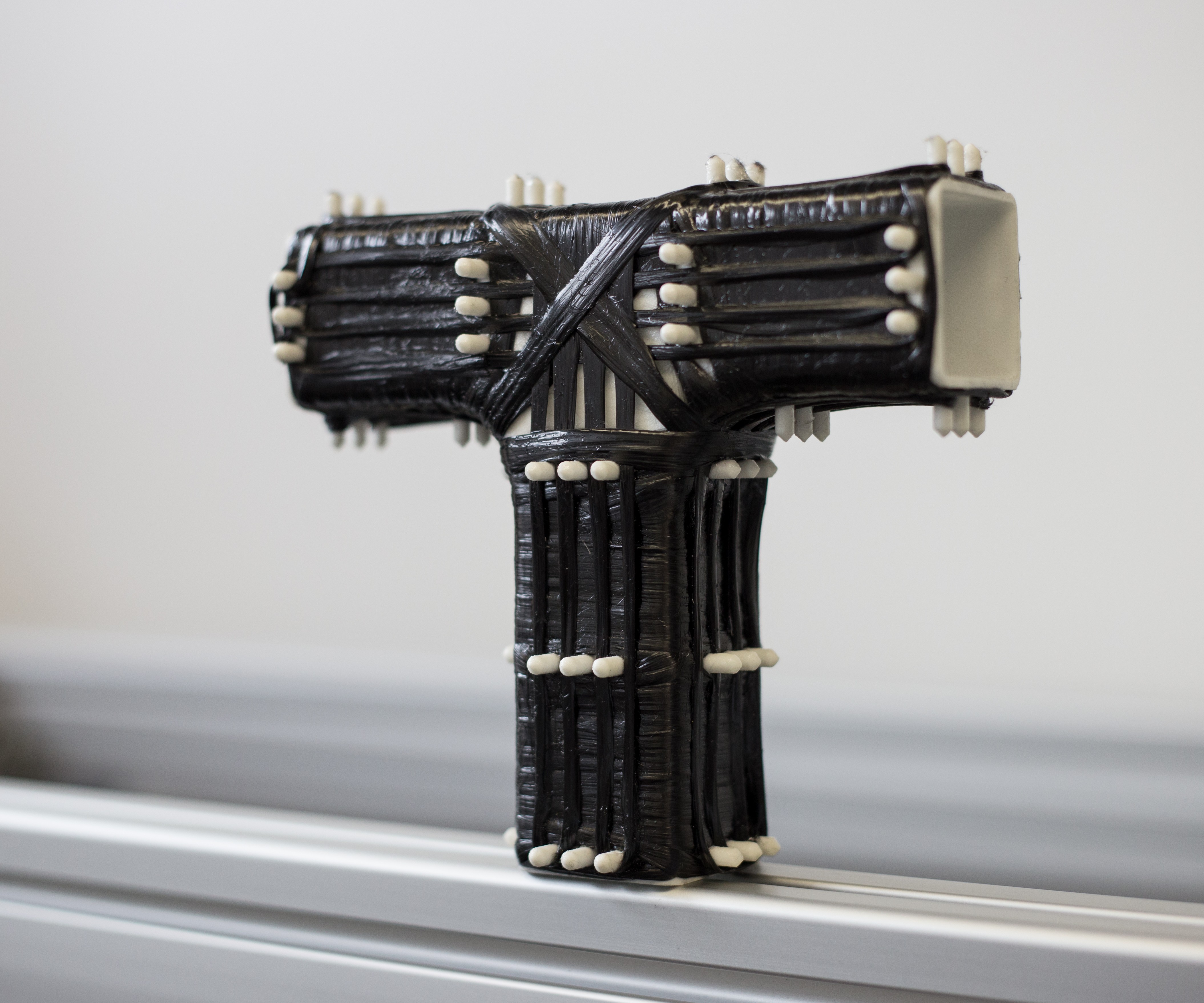
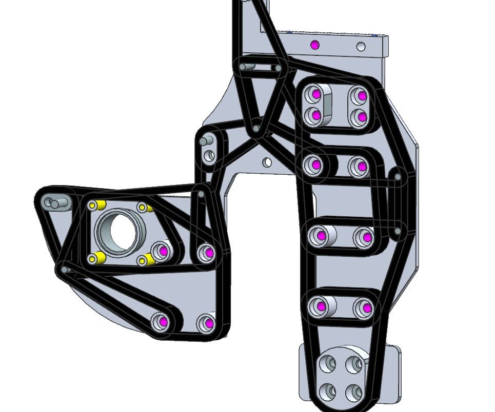
Fig. 4 New type of joining
Aluminum-framed robotic grippers used in auto assembly, shown here as yellow structures, can be lighter with components made by 3D winding carbon fiber and epoxy.
Source | Magna International
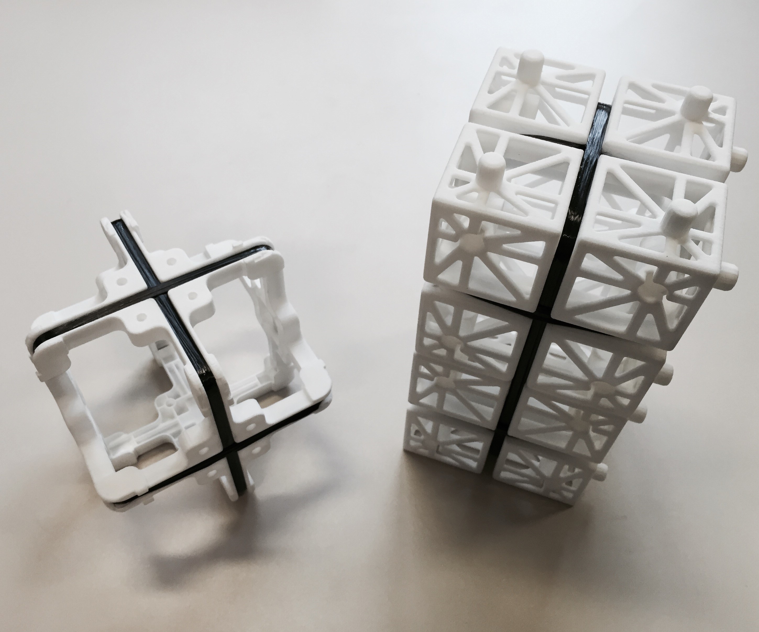
Snap-together, 3D-printed plastic modules joined by 3D filament winding. Source | CIKONI
A component made by 3D winding carbon fiber and epoxy around pins printed on a plastic mandrel.
Source | CIKONI
CAD analysis converts tension loaded areas into fiber paths for winding around plastic or metal.
Source | CIKONI
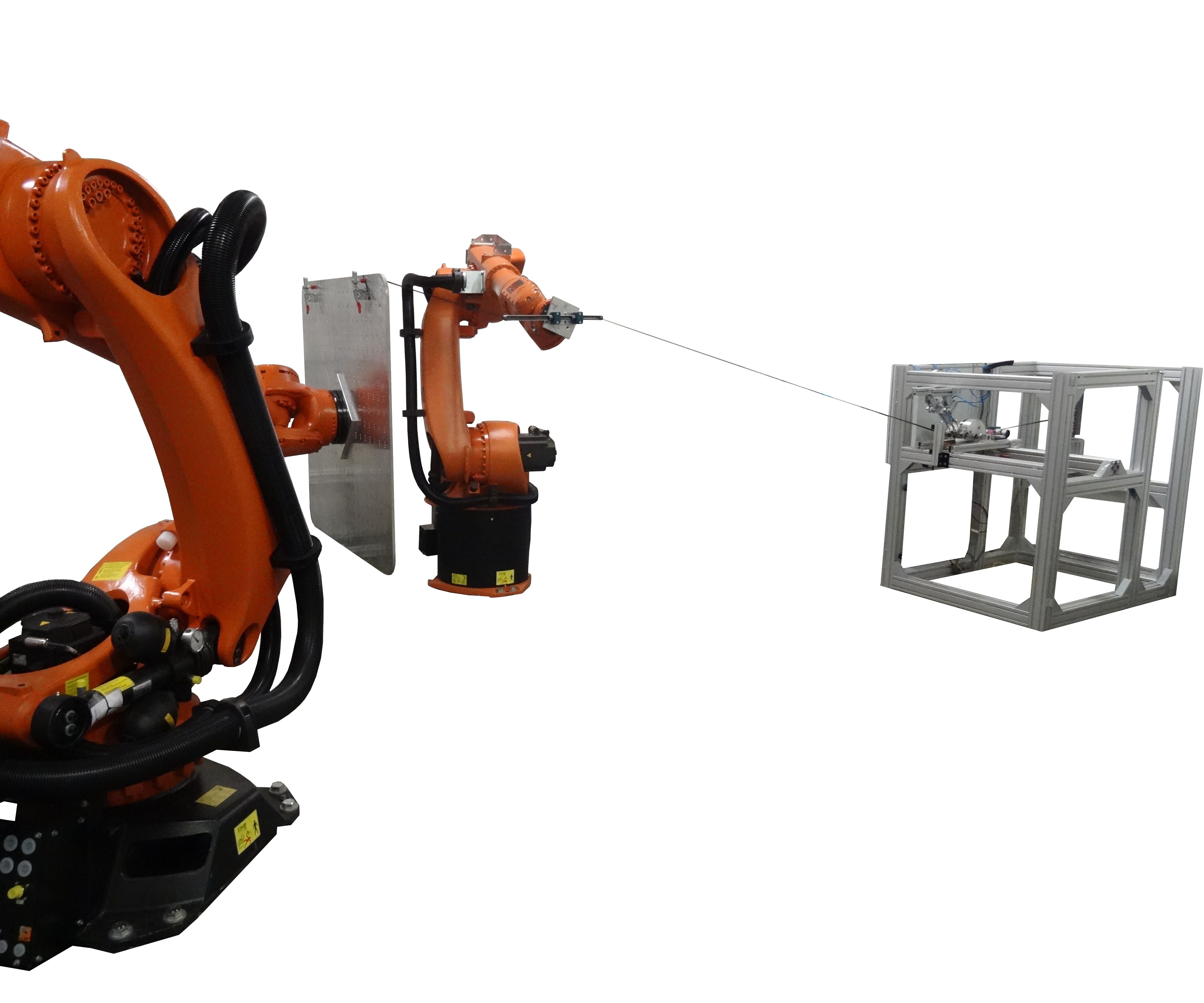
Fig. 5 Generative 3D winding
Developed to cut weight in assembly robot grippers by 50%, Daimler’s robotic and generative 3D wet winding process eliminates molds, waste and carbon fiber as the cost driver (aluminum winding pins now assume that role).
Source | Daimler
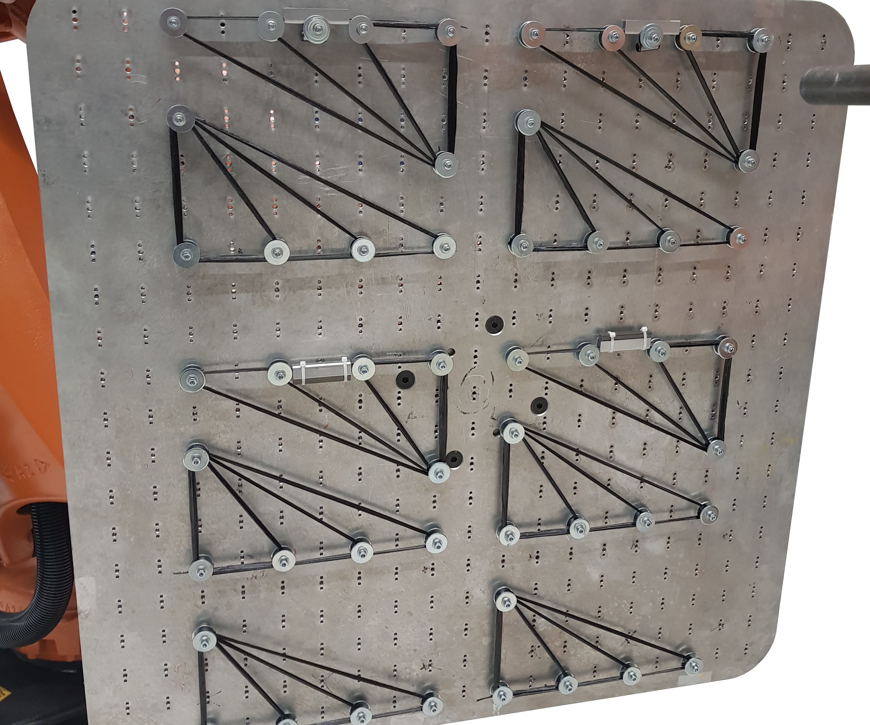
The winding tool (plate) in Daimler’s robotic and generative 3D wet winding process.
Source | Daimler


Filament winding, one of the oldest composite manufacturing processes, was used to produce solid rocket motor cases after World War II. By the early 1960s and ‘70s, commercial winding machines were also being used to fabricate fiber-reinforced pipes, pressure vessels and streetlight poles. Well-suited to automation, filament winding is fast, cost-effective and creates lightweight, high-performance structures.
Traditionally, filament winding impregnated fibers in a resin bath just prior to application on a rotating mandrel (tool) while keeping them in tension. Though wet winding is still popular, processes have also been developed to use prepreg tapes, towpreg or dry fibers, the latter serving as preforms for liquid molding processes. By varying the angle of fiber or tape placement, filament winding can produce tailored laminates to efficiently meet a range of loads. Typically, no further compaction is needed thanks to the tension maintained on the fibers/tapes.


Filament winding is now used to produce a range of composite structures including golf club and driveshafts, yacht masts, oars/paddles, bicycle rims and forks, small aircraft fuselages, spacecraft structures, car wheels and pressure vessels, the latter ranging from firefighter oxygen bottles and liquid propane gas (LPG) tanks to cryogenic fuel tanks for spacecraft measuring 5-10m in diameter and 10-15m long. Wind turbine manufacturer ENERCON (Aurich, Germany) is using automated filament winding systems installed in 2016 by Roth Composite Machinery (Steffenberg, Germany) to produce the shorter, inner sections for the segmented blades used in the E-115, E-126 and E-141 turbines.
One might think that such a standard and widely used process would see only incremental improvement. However, over the last few years especially, increased use of robotics and the latest digital technologies have dramatically increased filament winding production speeds (see “Automated filament winding enables competitive composite cylinders” and “Consolidating thermoplastic composite aerostructures in place, part 1”) and product complexity.
Examples in the composites industry include Cygnet Texkimp’s (Northwich, UK) high-speed, 3D winding machine, designed to produce complex layup parts that vary in both cross-section and shape. Similarly, filament winding specialist MF Tech (Argentan, France) is developing “very complex wound carbon fiber structures with ribs, beams and machined features for automotive applications,” says co-founder Emmanuel Flouvat. The company also is combining filament winding (FW) with automated fiber placement (AFP) and other processes, as is turnkey system supplier MIKROSAM (Prilep, Macedonia), which introduced its own hybrid AFP/FW work cell in 2017.
Winding is also being hybridized with 3D printing. Composites engineering firm CIKONI (Stuttgart, Germany) uses a robotic process to wet-wind carbon fiber/epoxy onto 3D printed plastic, composite or metal cores. Generative 3D winding — with a robot but without a core — is a technology being developed by Daimler (Stuttgart, Germany). Dubbed FibreTEC3D, and moving away from rotational structures altogether, the process wet winds carbon fiber/epoxy around aluminum pegs inserted into a tooling plate, producing load-tailored, lightweight structures without generating waste.
Where will filament winding end up? CW walks through these developments to find out.
Multi-filament winding
The quest to reduce cycle time has become a major driver of filament winding innovation over the last few years. Murata Machinery Ltd. (Kyoto, Japan) has achieved this by moving away from conventional single-tow/tape winding, where the fiber feed unit must move along the rotating mandrel multiple times to wind all of the fibers for just one layer. Instead, it has developed a multiple fiber system — what it calls multi-filament winding (MFW) — that simultaneously applies 48 to 180 tows/fiber inputs.
Murata presented its development work in 2015 at the 20th International Conference on Composite Materials (ICCM20, Jul 19-24, Copenhagen, Denmark) and installed the MFW-48-1200 system at the Institut für Textiltechnik der RWTH Aachen (ITA, Aachen, Germany) in 2017. The MFW-48-1200 comprises four main components: a creel, a ring-like adaptive nozzle, a rotating mandrel or liner unit and an annular hoop unit (Fig. 1). The MFW-48 creel contains 48 bobbins of fiber. The circular adaptive nozzle (also called an iris) feeds and applies the 48 fiber inputs from the creel onto a rotating mandrel or liner that moves horizontally in and out of the nozzle. The result is similar to braiding in that the fibers/tows cross over each other, but without inducing crimp. The winding angle is determined by the relative speed between the rotational and horizontal movement of the liner/mandrel and its diameter. Four additional fiber feeds may be applied at 90° via the hoop unit. Murata and ITA claim a complete layer can be applied in one pass, resulting in a cycle time 50 times faster than standard winding machines with a 90% increase in torsional stiffness compared to braided laminates. Reportedly the first machine of its type in Europe, ITA and Murata are now working to characterize the MFA process and begin prototyping applications such as hydrogen storage cylinders for automotive applications.
Robotic 3D winding: speed and complexity
Robots have been asserting influence on filament winding for some time. When MF Tech was launched in 2004, all of its systems were based on robots. This included the conventional filament winding arrangement where the rotating mandrel is kept in a fixed position and the fiber feed unit moves linearly. MF Tech simply mounted the fiber feed onto a robotic arm, gaining up to eight axes of motion. However, MF Tech also developed an unconventional arrangement where the rotating mandrel is carried by a robot, which moves it past a stationary fiber feeding unit (Fig. 2). This system could pick up a liner, wind a pressure vessel onto it and then place the wound tank into a curing oven.
More recently, filament winding systems have been developed where both the mandrel and fiber feed may be moved and rotated by robots. These robots cooperate to increase the range and accessibility for fiber winding, enabling larger structures as well as more complex fiber layups and shapes.
Both speed and complexity were goals for Cygnet Texkimp’s development of its robotic, high-speed 3D winding machine. The system combines rotation and fiber feed into a single mechanism that is robotically moved along the liner, mandrel or core, winding as it goes. Based on a 9-axis robotic winder conceived by University of Manchester professor Prasad Potluri, the Cygnet 3D winder uses two counter-rotating fiber application rings mounted together on the end of a robotic arm (see “High-speed, 3D winding of large, complex-shaped composites”). As the arm maneuvers the rings so that a complex-shaped mandrel is passed through their center, fiber is fed from eight bobbins on each ring — that number is scalable — and is wound onto the mandrel (Fig. 3).
“The inspiration for this was the F-35 [fighter jet] inlet duct,” explains Cygnet Texkimp managing director Luke Vardy. That roughly 3m-long, complex fighter jet part transitioned from a large, round cross-section to a smaller, square shape while tracing through a moderate, elbow-like curve. “This machine can match that complexity, offering more degrees of freedom than a stationary winder,” he adds. “The mandrel can be whatever shape you want.”
Cygnet’s 3D winder is also designed for speed, winding 24K or 48K dry carbon fiber at a rate in excess of 1 kg/min, “and creating a multiaxial laminate,” says Vardy. “We can vary the angle of the fiber, winding 30° on one ply, -30° on another ply and then we can apply 0° by adding another ring.” (Note: That ring would function like the hoop unit in Murata’s MFW system.) Vardy says that the winder is scalable, suitable for winding a car wheel or yacht mast, “yet we can make it big enough to wind a bridge arch, whole wind turbine blade or aircraft fuselage. It’s simply a matter a putting the robot on a rail and sizing the rings appropriately.”
Cygnet has also developed a traditional robotic filament winder from this technology. “It’s quite easy to switch out the 3D winding head for a filament winding head, using the same robot for both,” says Vardy. “We have mounted a driven creel to the robot to control fiber feed and tension to a high level of accuracy.” He explains that whether the creel contains four or 50 positions, each can be tensioned independently. “We can manage the machine speed to deliver higher resolution where you need smaller-scale features or complex geometries.”
He also notes a very accurate resin application system, which differs considerably from the conventional resin bath. “We bring in two-part epoxy from heated tanks through heated lines and mix in a Y nozzle at the winding head, less than a foot from the part,” says Vardy. “We are almost making towpreg on the fly. The tension control is actually spreading the fiber, so this is very close to ATL, but we don’t apply pressure for consolidation.”
The current R&D unit features a 3m diameter, 3m long mandrel and combines functions like trimming and machining. Vardy says it will next be used to run thermoplastic tape, adding, “we can run slit prepreg tape on this filament winder and on the 3D winder.” Cygnet will product the tape in-house, as it already supplies high-speed prepreg slitters to the industry.
Future hybrid cells
Flouvat at MF Tech confirms not only the use of more robots to make more complex shapes, but also the emergence of hybrid systems, which combine multiple operations into a single robotic cell. “We can cut into the shape, for local cutouts and fastener holes, after winding because the robot can use any type of tool — a CNC drill or milling tool, an ultrasonic cutter or a laser or ultrasonic welder for thermoplastic parts,” Flouvat explains. “After winding, the robot can change the head itself and switch to automated fiber placement. For example, we can wind tubes and then apply local patches of unidirectional tape. All of the technologies we find in the composites industry we want to incorporate into our machines.”
MF Tech also equips its machines to capture manufacturing data — fiber tension, resin temperature, fiber and resin batch and operator information — via industrial internet of things (IIoT) technology. “This is required now for automotive and aerospace manufacturing,” says Flouvat. With regard to cycle time, Flouvat says wet winding speed is limited by the fiber’s ability to take up resin. Typical speeds range from 1-2 m/s up to 10 m/s depending on part and process complexity. “Other processes use prepreg or dry fiber and are faster,” he notes.
3D printed cores for 3D winding
CIKONI also has an interest in hybridized filament winding, which came through its founders. Farbod Nezami had modified FW to build grippers and truss parts for assembly robots at Daimler, while Diego Schierle was using it to build tailored, high-performance pressure vessels for cars at the German Aerospace Center’s (DLR) Institute for Vehicle Concepts (Stuttgart). Although CIKONI provides design and engineering services across the spectrum of composites materials and processes, it has already sold two customized winding cells for development work at German automotive suppliers and is close to finalizing a contract for its first automotive production machine.
Nezami says 3D winding has proven to be a particularly good solution for the manufacture of robot grippers because they are very specialized, yet need to be lightweight. “Because each gripper is different, only one or two of each kind is made, which makes tooling cost-prohibitive,” he explains. “We can 3D print a polymer T-mandrel with pins, and then 3D wind carbon fiber wet out with room-temperature cure epoxy resin around these pins [Fig. 4].” The core and pins can remain in the part, or be melted/washed out. If the part has high compression loads, the core can be 3D printed metal, which Nezami says, “enables a very interesting hybrid design. We use finite element analysis [FEA] to identify areas of tension and compression, which guides which materials and hybridization strategy we choose.” The black passes in the CAD rendering at the bottom of Fig. 4 show 3D filament winding on top of the gray CNC machined metal underneath.
Another concept CIKONI is pursuing are lightweight truss structures for robots using multiple 3D printed or injection molded “Lego-like” modules that click together. “We then 3D wind to make this a load-bearing structure,” explains Nezami. “Thus, 3D winding becomes a new type of joining technology.” CIKONI used this technique to eliminate vibration in a 1.5m truss with cameras mounted at either end, used to calibrate a head up display (HUD) system in a vehicle application. “We needed to replace the previous aluminum tube, yet achieve a stiff, lightweight structure across the span,” says Nezami. “We did this by 3D winding carbon fiber/epoxy around a printed polymer truss with some metal elements included for attachments.”
He notes that additive manufacturing with polymer is typically more cost-effective than 3D printed metal. “This technique provides better performance at a low investment and high productivity with low production cost,” Nezami asserts. “We can eliminate tooling, lower scrap costs, use minimal carbon fiber and resin and put the fiber exactly where it needs to be, depositing directly from the bobbin in unidirectional, noncrimp layers. We are pushing one-shot production of innovative composite frameworks beyond currently known limits.”
Generative 3D winding
The aforementioned development work on grippers at Daimler, pursued by the company’s Process Development Dept., has led to a new, potentially revolutionary, coreless 3D winding technology for the manufacture of production robot parts and automotive parts. Referred to as FibreTEC3D, the Daimler technology involves two cooperative robots, one that holds and manipulates an aluminum tooling plate with pins protruding from the surface, and one that wet winds carbon fiber around the pins (Fig. 5). Daimler assembly process engineer Niklas Minsch calls these pins deviation points because they deviate the fiber path, which forms the composite structure.
“The idea is that this manufacturing method and the parts it produces are generative,” says Minsch. In generative design, a part’s geometry is not predefined, but is instead computer generated by applying advanced algorithms to data derived from the application’s requirements and constraints — size envelope, loads, strength, stiffness, impact, deflection, cost, etc. (see “Generative design and continuous 3D fiber deposition” and “Connecting the Dots: Generative design, bionic structures and future composites”). In short, the requirements of the application dictate the design. Applied to manufacturing, this approach enables the economical production of highly optimized, small-series products. Typically, the more complex a part is, the more generative design and manufacturing pay off.
“The initial idea was to make assembly robot grippers lighter, enabling us to downsize the robots, which saves money, and also extends their reach,” Minsch explains. “Our car development department saw what we were doing and wanted to use the same technology to make a body part.” These parts start with a topology-optimized design, he says, “so that we are putting the right material in the right places, which minimizes the amount of material needed and means carbon fiber is in tension.”
The part’s digital design directs placement of the pins and generation of the robotic winder code — the combination, in turn, actualizes the part. The entire design process is managed by software developed in cooperation with the Institute of Textile Machinery and High Performance Materials (ITM) at the TU Dresden (Dresden, Germany). “The deviation points (pins) can be made higher or lower to create the 3D depth versus a planar structure,” Minsch observes. “Longer deviation points will induce more bending moment, so there is some tradeoff. The structures we are making are more like 2.5D.”
“We are now at the point where we can say we don’t need two robots,” he adds. “We can fix the tooling plate and have just one robot to wind the fiber onto it.” Minsch explains that because there is no cutting and no waste, the aluminum becomes the cost driver, not the carbon fiber. “We’re using 24K tow, which is typical for automotive,” he adds. The resin is a room-temperature cure laminating epoxy because there are no high-temperature requirements for the first production part. “We are also able to integrate metal inserts easily for wear points,” says Minsch. “This was necessary when we started with grippers because they need a lot of attachment points — which is also why we don’t use composite pultrusions. With our approach, we can match the strength and stiffness of a standard aluminum gripper but at 50% of the weight.”
If towpreg is typically faster to filament wind, why is wet winding preferred in the FibreTEC3D process? “We tried towpreg,” says Minsch, “but it was too sticky and damaged the roving. This doesn’t happen with wet winding because the roving is slippery.” He notes towpreg also requires compression, post-winding, to compact the separation between plies. “The tension in wet winding compacts the fiber as it is wound,” says Minsch. “We’re using pretension as well, which is important for final part properties.” He concedes that additional compression could increase composite properties by 10-15%, “but it increases cost severely because you then need tooling, vacuum and pressure. This isn’t a rocket motor casing. Our approach provides sufficient properties and meets the cost target.”
Eliminating carbon fiber knockdown
Daimler is not the only company pursuing this type of innovative 3D winding. German inventor Peter Fassbaender, working with Automotive Management Consulting (AMC, Penzburg, Germany), has developed xFK in 3D. As described in the 2016 lightweight.design magazine article “CFRP Profiles in a 3D Winding Process,” the xFK in 3D process involves robotic winding of a fiber roving saturated with epoxy resin around a simple metal positioning fixture. It creates ultra-light, bionic composites with fibers arranged specifically to match each part’s loads and desired functions. By winding around metal and/or plastic inserts, the process also enables cost-effective functional connections, historically a challenge for composites.
AMC has been working with towpreg and composites technology supplier SGL Group (Wiesbaden, Germany) to further develop xFK in 3D and displayed several bicycle and automotive parts at JEC World 2018. One of these, a carbon fiber bicycle chain ring, can reportedly cut weight up to 70% vs. the aluminum version. "In terms of quality, reproducibility, process speed and clean processing, SGL Group offers a material that complements xFK in 3D extremely well," notes AMC managing director Rainer Kurek. It also provides a wide palette of potential fibers and matrices.
Flouvat’s vision for composite winding is the possibility to produce all parts on a car in the future: “You can imagine filament winding will become a mix of 3D printing, AFP and winding to make any kind of part. We are working on this now.” Vardy explains Cygnet Texkimp’s motivation for its 3D winder development: “It’s not about what you can’t do today, it’s about what you can’t do at a palatable production rate. We are offering precision and an understanding of how to handle and apply fibers with minimal fiber damage and waste. You’re paying a lot for carbon fiber. You don’t want to knock down its performance.”
And that, ultimately, is the driver for and potential disruptive power of the latest filament winding developments: putting fiber where it needs to be with precision, speed and practically zero waste.


.jpg;maxWidth=300;quality=90;format=webp)


Related Content

Recycling end-of-life composite parts: New methods, markets
From infrastructure solutions to consumer products, Polish recycler Anmet and Netherlands-based researchers are developing new methods for repurposing wind turbine blades and other composite parts.
Read More
Infinite Composites: Type V tanks for space, hydrogen, automotive and more
After a decade of proving its linerless, weight-saving composite tanks with NASA and more than 30 aerospace companies, this CryoSphere pioneer is scaling for growth in commercial space and sustainable transportation on Earth.
Read More
Moving toward next-generation wind blade recycling
Suppliers, fabricators and OEMs across the composite wind blade supply chain ramp up existing technologies, develop better reclamation methods and design more recyclable wind blades.
Read More
Forvia brand Faurecia exhibits XL CGH2 tank, cryogenic LH2 storage solution for heavy-duty trucks
Part of its full hydrogen solutions portfolio at IAA Transportation 2022, Faurecia also highlighted sustainable thermoplastic tanks and smart tanks for better safety via structural integrity monitoring.
Read MoreRead Next

Automated filament winding aids segmented blade production
Roth Composite Machinery system is part of ENERCON’s optimized production for modular blades.
Read More
Automated filament winding enables competitive composite cylinders
Carefully controlled, robust, volume processes offer fabricators of Class IV LPG/CNG tanks a means to meet increasing demand in Europe and Asia.
Read More
Cygnet Texkimp and University of Manchester develop 3D winding technology
The machine is based on a 9-Axis robotic winding concept and winds carbon fiber into lightweight parts for automotive and aerospace markets.
Read More