


Combining AFP and FFF
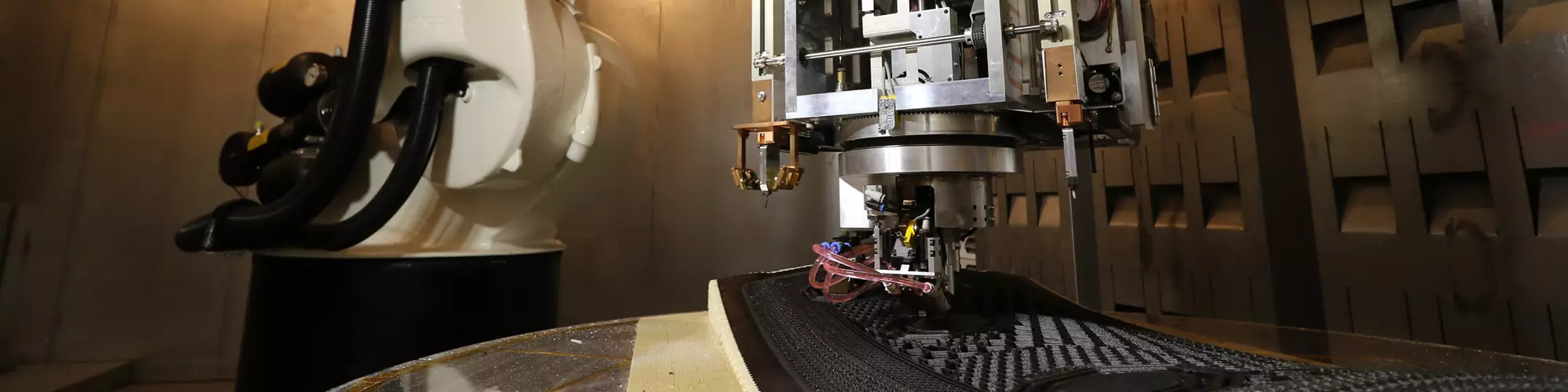
Shown here printing the bay door demonstrator in Fig. 2, the SCRAM cell features a scaled-down, extremely dexterous in-situ consolidated thermoplastic AFP head positioned between two fused filament fabrication (FFF) nozzles — one for printing soluble support tooling and the other for unreinforced or chopped fiber-filled filament. Photo credit: Electroimpact
Founded in 1986, Electroimpact (Mukilteo, Wash., U.S.) is a global tooling and production automation supplier that claims to be the world’s largest integrator of aircraft assembly lines. In composites, the company is known for its advanced technology in high-speed automated tape laying (ATL) and fiber placement (AFP) systems. Electroimpact emphasizes that it is engineer-driven — 400 of its 600 employees have engineering degrees — with developments conceived and completed by the same engineer team, from concept through design, manufacturing, installation and customer buyoff.
In July 2020, CW reported on the company’s new Scalable Composite Robotic Additive Manufacturing (SCRAM) system. Here, we share our interview with part of SCRAM’s engineering team: Project manager Cody Brown, process development and controls engineer Ryan Bischoff and lead mechanical engineer Reese Allen. Their explanation of this continuous fiber additive manufacturing’s origin, implementation and future provides insights into what the next generation of composites production might look like.


Aiming for large-scale FDM
Brown: “We have been working on this for four years but wanted to wait until we could show that it would produce real, aerospace-quality parts. Our original goal was to produce a large-scale fused filament fabrication (FFF) 3D printer that could create complex parts using continuous fiber. We didn’t set out to develop an AFP-type process, but as we were trying to increase fiber volume and achieve higher physical strength in the printed parts, we hit a wall with FFF. It’s just not a suitable process for in-situ consolidation with high fiber content and low voids. So, we have ended up with a process that combines thermoplastic composite AFP with FFF using unreinforced and/or chopped fiber-filled filament.”
Allen: “AFP is actually an additive manufacturing process. In SCRAM, however, we’re not using it in a conventional way with a fixed, hard tool but instead printing a tool that we can wash out afterward to create very complex geometries that are truly structural.”
Brown: “We can put that soluble tool in places that aren’t grid-locked so that you can create internal cavities. The goal is not to compete with our large AFP systems, but instead to make a very dexterous system as close to a 3D printer as you can get. To do this with true six degrees of freedom and accuracy is actually very complicated. The resulting cell eliminates fasteners and adhesives, manufacturing integrated, complex parts that can be iterated very quickly.”
High-performance for aerospace
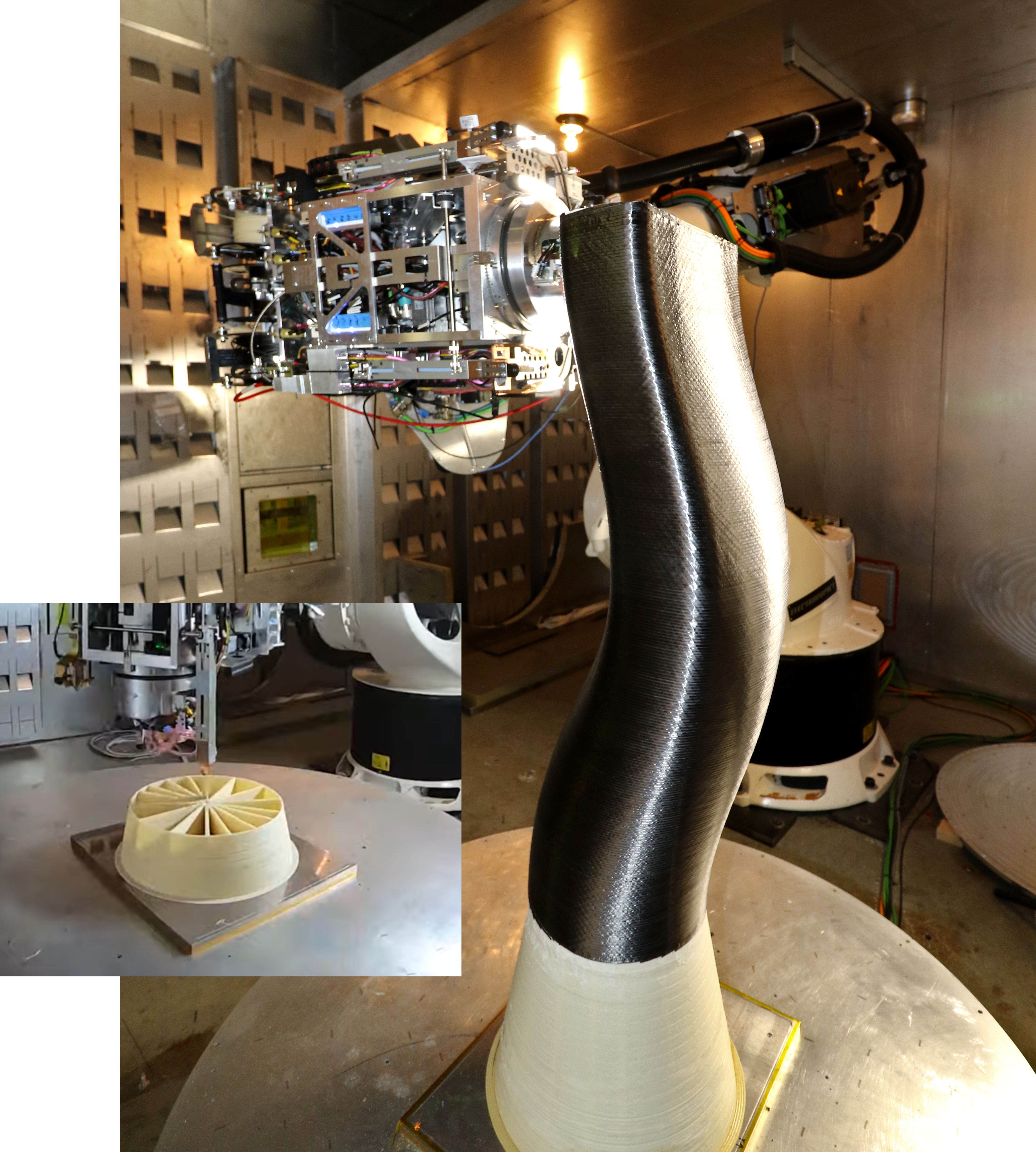
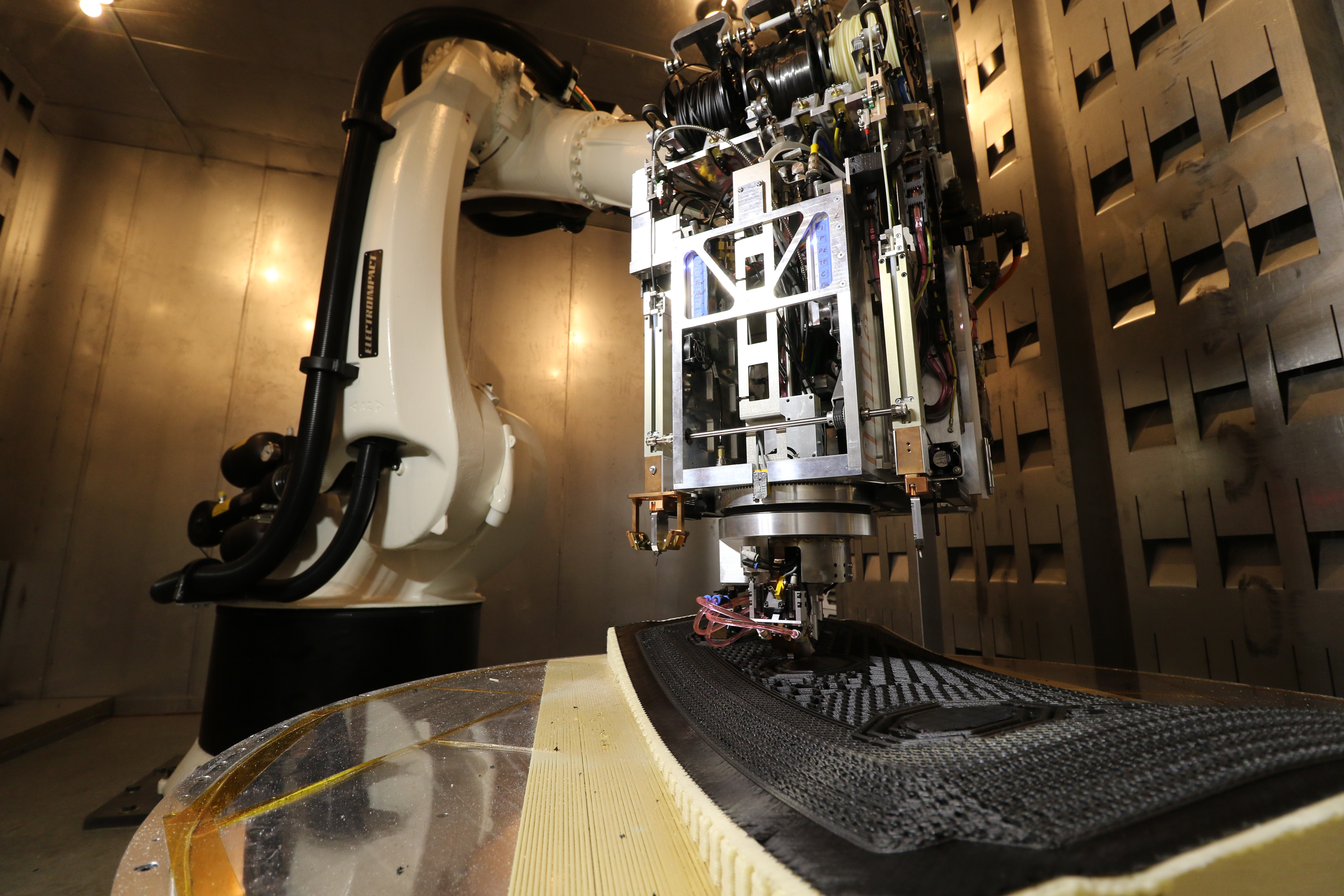
Fig. 1. Complex duct demonstrator
Bischoff: “In the demonstration video, we printed the tool as a 2.5D soluble support structure and then smoothed that out to create a good layup surface using a special process to eliminate the ridged structure from the printed beads. We then wrapped this with continuous carbon fiber-reinforced thermoplastic tape. There are actually two skins in that part, an inner and outer skin, separated by 3D ribs which were printed using FFF with chopped carbon fiber filament. So, the process was: Print the tool, AFP the quasi-isotropic inner skin, FFF the ribs and then AFP the exterior skin. For the tooling, we are working now to refine a water-soluble material that is showing promise.” Photo Credit: Electroimpact
Brown: “The initial applications we are targeting in aerospace and defense mandated we start with PEEK [polyetheretherketone]. We then worked with PEKK [polyetherketoneketone] and low-melt PAEK [polyaryletherketone] with dramatic success.”
Bischoff: “Coefficient of thermal expansion [CTE] is your biggest enemy. This is the reason why using PEEK is so challenging — it loves to crystalize and shrink. Although the CTE for PEKK and other PAEK resins is not zero, their crystaline structure is much more controllable and therefore easier to work with. Alternate PAEKs also offer much better processability and higher layup speed.”
Allen: “Thermal gradients have to be avoided due to the CTE issue, so you try to keep the process and part as isothermal as possible. Otherwise, you end up with warping. Using the heated chamber is a must — even if you’re not keeping it at a high temperature — just to ensure there are no drafts and that one part of the print is not at a different temperature than the rest.”
Laser-based cell
Brown: “A lot of things that enable this system didn’t exist when we started, including the PAEK tape and the compact, high-power laser we use, as well as true six-axis additive manufacturing CAM software.”
“The SCRAM head uses two 3D printing nozzles on either side of the AFP system [opening image]. One is used to print the soluble tooling and the other prints unreinforced or chopped-fiber filament. You can see that one is equipped with a scaffold. This holds a set of mirrors to redirect laser light around the nozzle tip and heat the substrate. This allows us to achieve exceptional interlayer bond strength compared to traditional FFF. The lights on the system are to illuminate the part for the cameras [Fig. 2]. We use these all over so the operator can safely see what is going on without danger from the laser.”
Fig. 2. Laser cell, aero parts
The lights shown here are not the cell’s laser, but instead enable cameras to show parts clearly during printing to the operator, who remains outside the cell for laser safety reasons. The demonstrator spar section (top) and bay door (bottom) show the quality and novel complexity that SCRAM can achieve. Photo credit: Electroimpact
Material formats and porosity
Brown: “We have run many different materials, most of them custom made to our specification of fiber, resin, fiber volume and dimensions. We have recently been experimenting with more commercially available slit tows. The chopped fiber FFF filaments are also made to our specification using the same resin and fiber that we select for the continuous fiber tapes. We have used 1-, 3.5- and 6.35-millimeter-diameter filaments. We can go larger but haven’t had a need to yet.”
“We achieve 50-60% fiber volume for the AFP, but substantially less for the FFF portions since those are extruded. Porosity is on the order of traditional out-of-autoclave processes but has been dramatically decreasing as we refine the process. Using extremely high-quality materials, and in a lab setting, we have achieved porosity under 0.5%, measured using CT [computed tomography] scans. As always, there are a huge number of variables that impact this number and when we are producing very complex parts it is a challenge to maintain low porosity. We have performed lots of destructive and non-destructive testing of parts and coupons made with the system.”
High-accuracy, robotic control
Bischoff: “SCRAM delivers high-accuracy robotic technology. Standard off-the-shelf robots are an affordable solution to achieve 6-degree-of-freedom movement for placing and printing, but they are nowhere near accurate enough for aerospace-quality AFP. We started figuring out how to apply these robots to aerospace AFP systems years ago. You really have to understand the fundamentals of the system and the issues with achieving accuracy. We have an entire robot group of 60-70 engineers, and this is all they do.”
“It is an incredibly complex issue to achieve high positional and path accuracy. You have inaccuracies in the robot (CTE of the robot, backlash, vibrations, etc.) and in the external axis, tool point calibrations, a spinning part frame and several other sources. Not accounting for/addressing any one of these can be catastrophic once you start printing in a true 3D space. To accomplish this, we throw out the controller that comes with the robot and run everything with a Siemens CNC. We then add Electroimpact’s patented secondary feedback onto all of the robot axes, which takes us from a tolerance of 30-40 mils [0.030-0.040 inch] down to ±15 mils [0.015 inch]. Then we apply a high-order kinematic compensation to reach ±10 mils [0.010 inch].”
Speed, end effectors and rotating print table
Brown: “We are using in-situ consolidation, so the application speed will not be near that for thermoset prepreg tapes. Also, this is a robot, not a large, stiffened gantry platform (like AFP), which is built for higher speeds. And speed is not just laying and printing but includes the lead time for tooling as well. The real metric is how quickly can you have a digitally manufactured part in hand?”
“The part in the video was 36 inches tall (with the printed base it exceeded 4 feet) and its diameter was 16 inches. If we ran nonstop in shifts, we could produce this in a few days, which is an incredibly short time to have a part in hand. Parts are also produced straight from the CAD file, so if you need to iterate, you change the CAD, repost the tool paths and print the new part.”
Allen: “Right now, for printing the support tool, we have a scaled-up, filament-based process. Throughput is kind of slow, which impacts the print time. In July, we commissioned our first end effector with a pellet screw extruder. This will increase output but will produce thick beads, so we will also add a milling end effector for machining the printed surface.”
Brown: “We will have a family of compatible end effectors that the robot can pick up and drop off, performing a wide variety of additive and subtractive functions as required. The end effector pick-up and drop-off procedure is fully automated, which is a standard feature on all of our AFP systems as well as SCRAM. The entire end effector is attached to the robot using an automatic tool change interface module and there are stands for end effector storage.”
“The system prints onto an external rotational axis and is controlled by the CNC. We have this because the robot alone cannot reach every point on the parts we want to make. Down the line, we intend to put the system on rails to make bigger parts, but we want to refine the system at this scale first. We have discussed using two robots, and we know philosophically how we would go about it. (We have produced other integrated multi-robot manufacturing systems.) But when you have two robots working in overlapping work zones, the controls become extremely complicated.”
Future flexible production made possible
Brown: “This multifunctional cell will deliver value to the end customer. It doesn’t always have to produce continuous fiber-reinforced thermoplastic parts. By adding extrusion and milling to the continuous fiber deposition, we widen its range and flexibility. For example, some of the structures we’ve demonstrated have subtractive functions within the part build. The robot then checks the surface and closes that cavity out. This is not currently possible without multiple steps, specialized tooling and/or final assembly of some sort.”
“However, there is an even greater theme than just producing parts. Long-term, this approach has a chance to dramatically shift the way aerospace and defense systems are designed and manufactured. No more will a single production line be dedicated to a single product. Instead, production will be flexible. Also, if you can reduce tooling, you can reduce spares sitting on the shelf. This flexibility has impacts all through the supply chain, including reducing waste due to expiration of materials.”
Bischoff: “With a small handful of SCRAM cells and digital designs, all you have to keep on hand is raw material feedstock, versus dozens of fixed tools and limited-shelf-life thermoset materials.”
Brown: “We have a way to go yet before production is truly handled this way, but now you can clearly see how it’s possible.”


Related Content

The state of recycled carbon fiber
As the need for carbon fiber rises, can recycling fill the gap?
Read More
Composite rebar for future infrastructure
GFRP eliminates risk of corrosion and increases durability fourfold for reinforced concrete that meets future demands as traffic, urbanization and extreme weather increase.
Read More
Novel dry tape for liquid molded composites
MTorres seeks to enable next-gen aircraft and open new markets for composites with low-cost, high-permeability tapes and versatile, high-speed production lines.
Read More
Materials & Processes: Resin matrices for composites
The matrix binds the fiber reinforcement, gives the composite component its shape and determines its surface quality. A composite matrix may be a polymer, ceramic, metal or carbon. Here’s a guide to selection.
Read MoreRead Next

Composites end markets: Energy (2024)
Composites are used widely in oil/gas, wind and other renewable energy applications. Despite market challenges, growth potential and innovation for composites continue.
Read More
From the CW Archives: The tale of the thermoplastic cryotank
In 2006, guest columnist Bob Hartunian related the story of his efforts two decades prior, while at McDonnell Douglas, to develop a thermoplastic composite crytank for hydrogen storage. He learned a lot of lessons.
Read More
CW’s 2024 Top Shops survey offers new approach to benchmarking
Respondents that complete the survey by April 30, 2024, have the chance to be recognized as an honoree.
Read More