
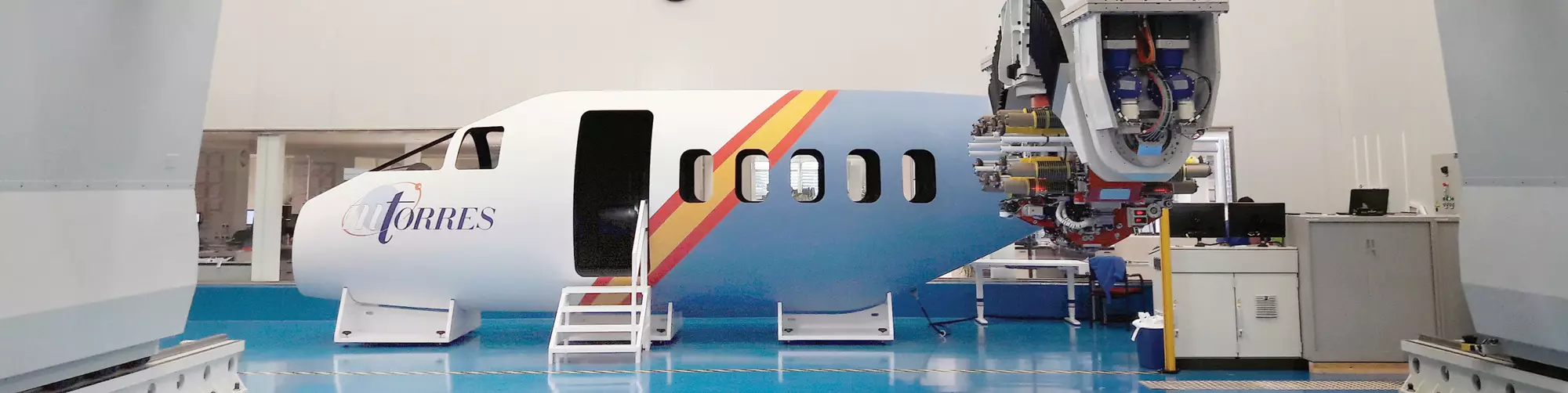

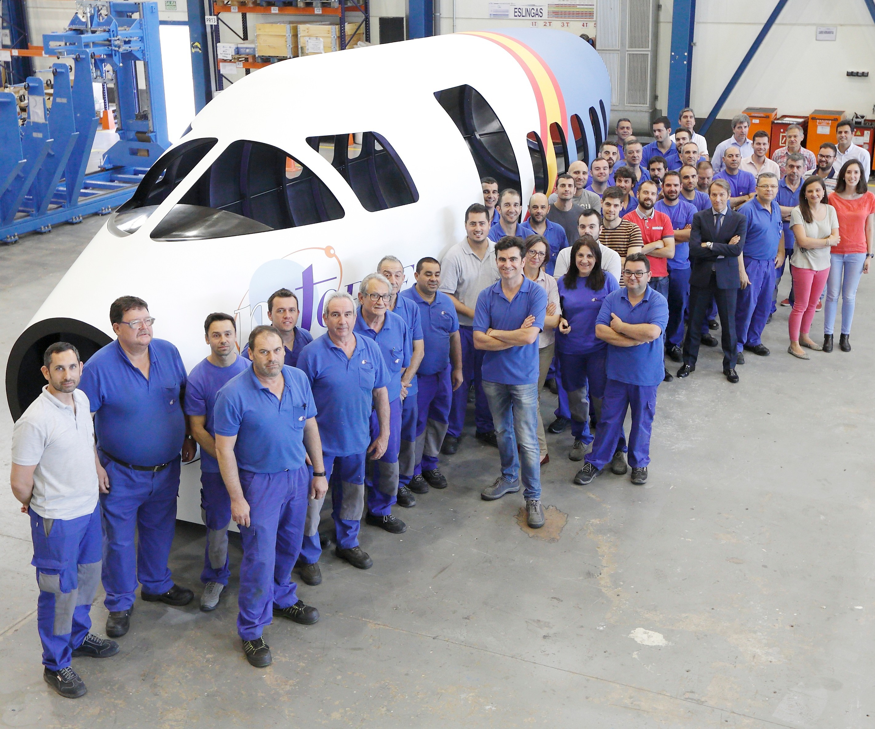
Fuselage of the future?
MTorres’ (Torres de Elorz, Navarra, Spain) mold-free, fastener-free aircraft fuselage demonstrator is shown here with the crew that created it. A detailed concept showing an almost completely automated factory for manufacturing these fuselages was released at the 2018 JEC World composites event.
Source (all photos/images) | MTorres
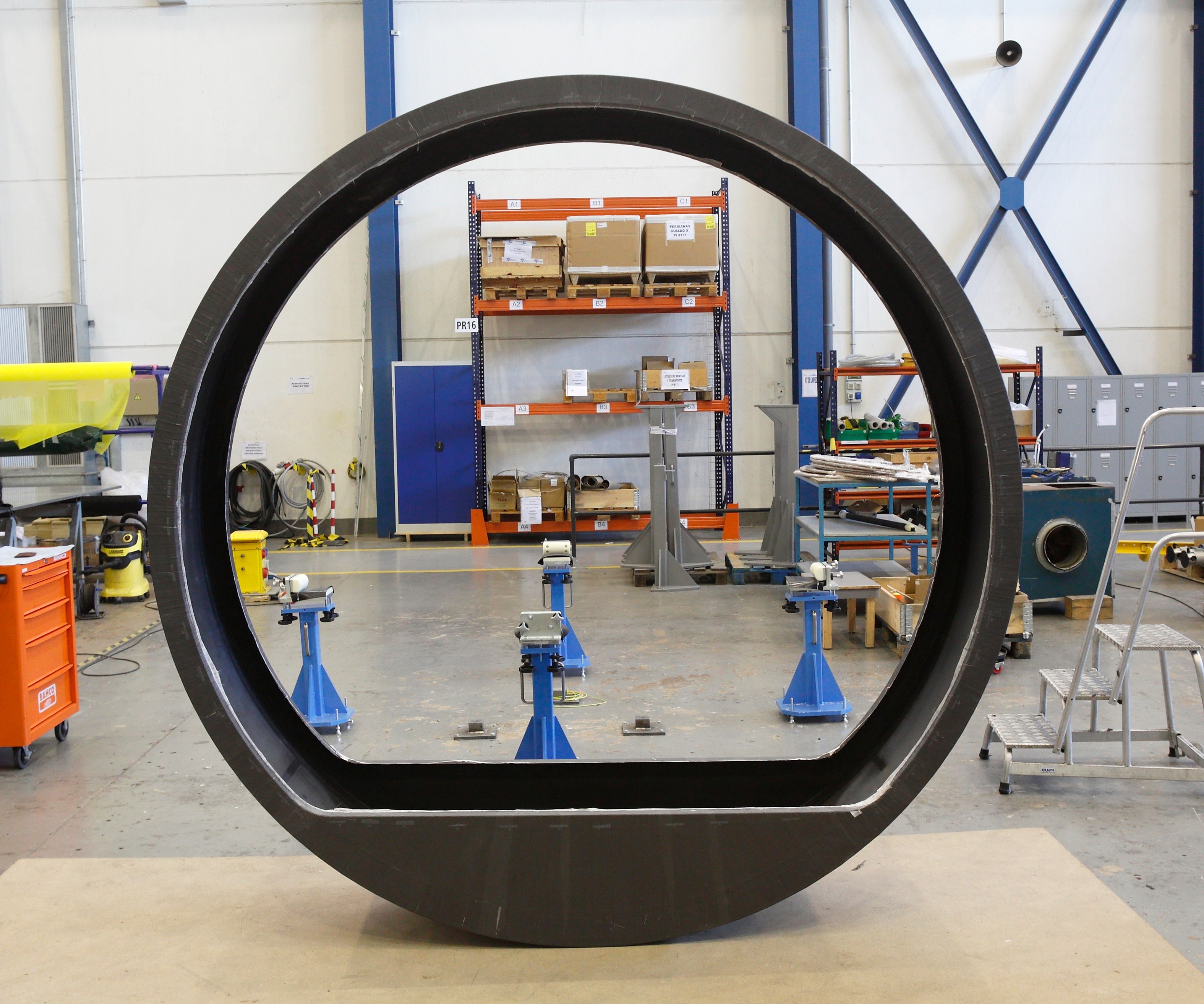
Fig. 1: Replacing tools and stringers with ride-along rings
“Elemental” parts are fabricated first, including floor panels and frames or in the case of a fuselage, rings, like the one shown here. Such frames and rings, made of carbon fiber composite, are butted together and bonded, taking the place of and performing the same function as a mold or mandrel when the AFP equipment overwinds the fuselage skin (see the step photos that follow).
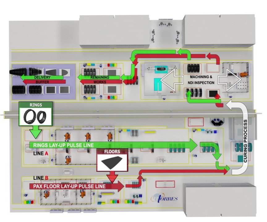
Step 1: Factory of the future: Overhead view
An overview of MTorres’ factory concept for automated production of aircraft, using robots.
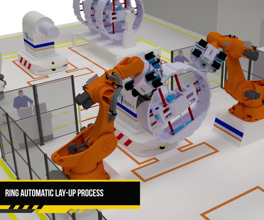
Step 2: “Rings” or fuselage frames are produced first, via automated fiber placement (AFP) on metal mandrels. Two robots would work together, to reduce layup time, as the mandrel rotates on the positioning robot. Note that the rings have grooves, which will act as exterior stringers when overwound during final assembly.
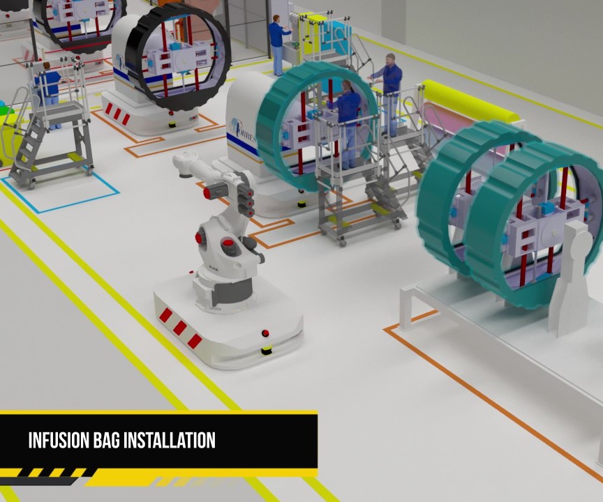
Step 3: After completion of the ring layup, the positioning robots move the rings to the bagging area, where the rings are prepped for resin infusion, and cure. Note that the flat plates that extend across the bottom of each ring will act as supports for the fuselage cabin’s floor panels.
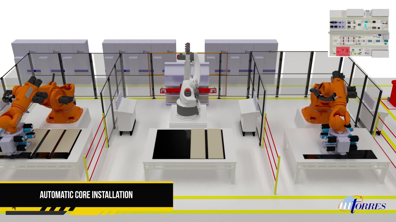
Step 4: On a parallel production line, the flat floor panels are produced. A moving line brings flat table molds into position in front of stationary robots, which lay the lower skin, core panels and upper skin, in sequence.
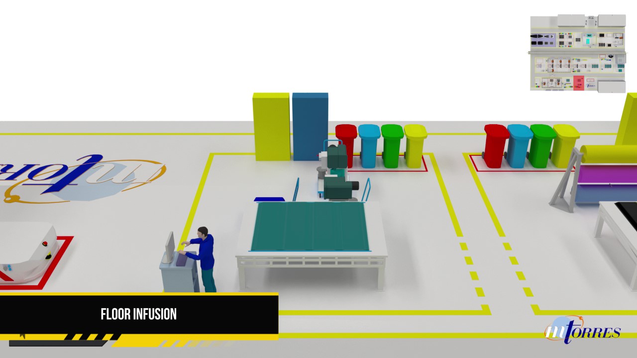
Step 5: Like the rings, floor panels are bagged and prepped for infusion and oven cure by technicians.
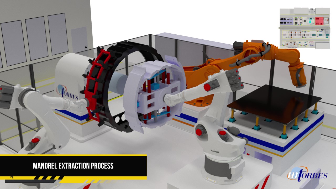
Step 6: After oven cure is complete, parts are transported to the machining area, where a robot trims and creates openings in the rings’ floor supports, and trims the floor panels. Shown here is a robot collapsing and removing a ring’s mandrel. Following this step, the elemental parts undergo non-destructive inspection.
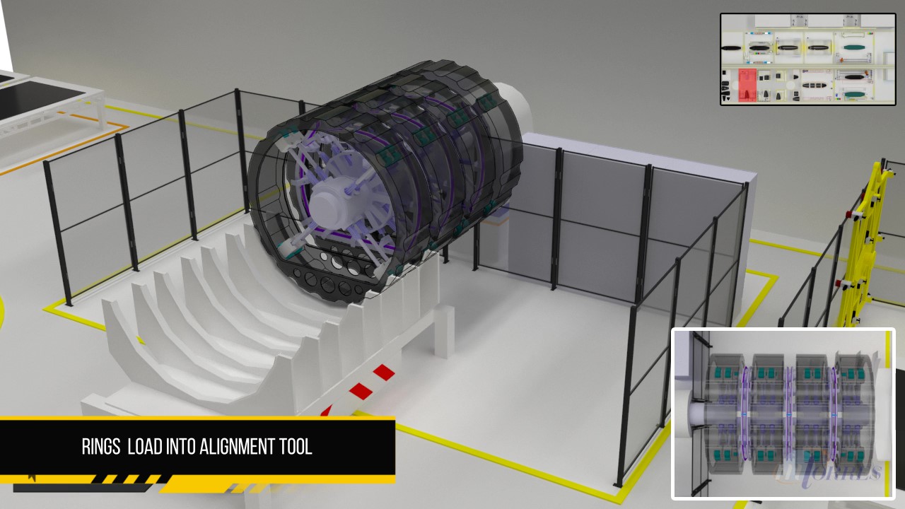
Step 7: In a second building or manufacturing area, where final body joinery takes place, rings are brought to an alignment tool (note the robotic transfer jig that has transferred the group of four rings), where robots check for ring alignment and fit, and dispense.
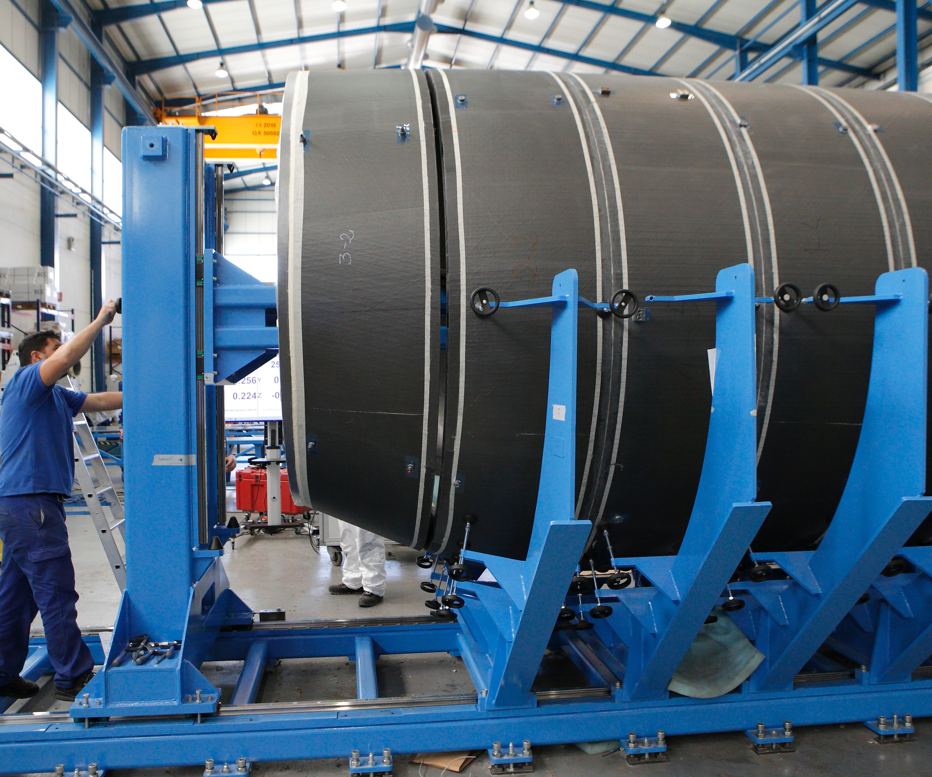
Step 8: This photo shows the demonstrator fuselage rings being aligned and bonded, in this case, manually, but on a similar alignment tool as would be used in the factory concept.
Step 9: Here, a larger alignment tool brings together all the fuselage segments, from nose cone to tail end, to check for fit, apply adhesive and bond the segments to create a complete fuselage structure.
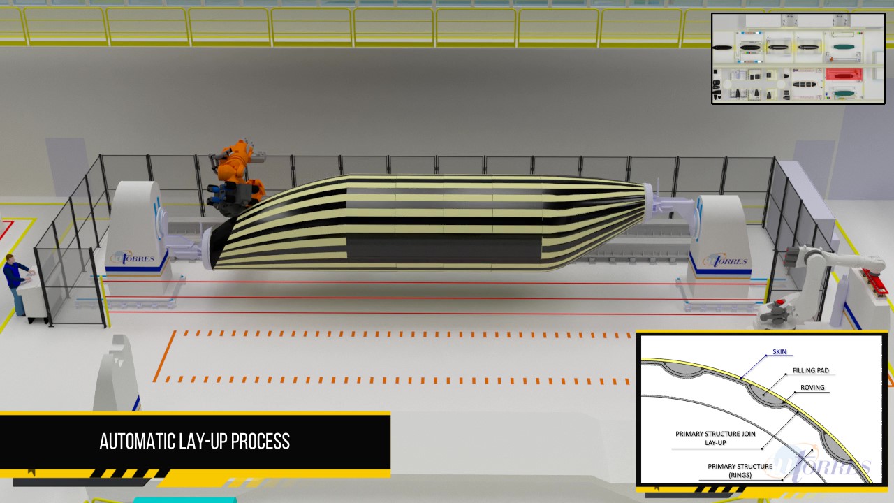
Step 10: After the complete fuselage is moved to the next station, it is installed in a layup machine with headstock and tailstock, and overwound with dry carbon fiber to form the fuselage skin. This image shows the filler material that has been robotically placed within the ring grooves; as the skin covers the grooves, it creates external stringers to stiffen the fuselage structure, says MTorres. The filler can be left intact as insulation or removed after skin cure.
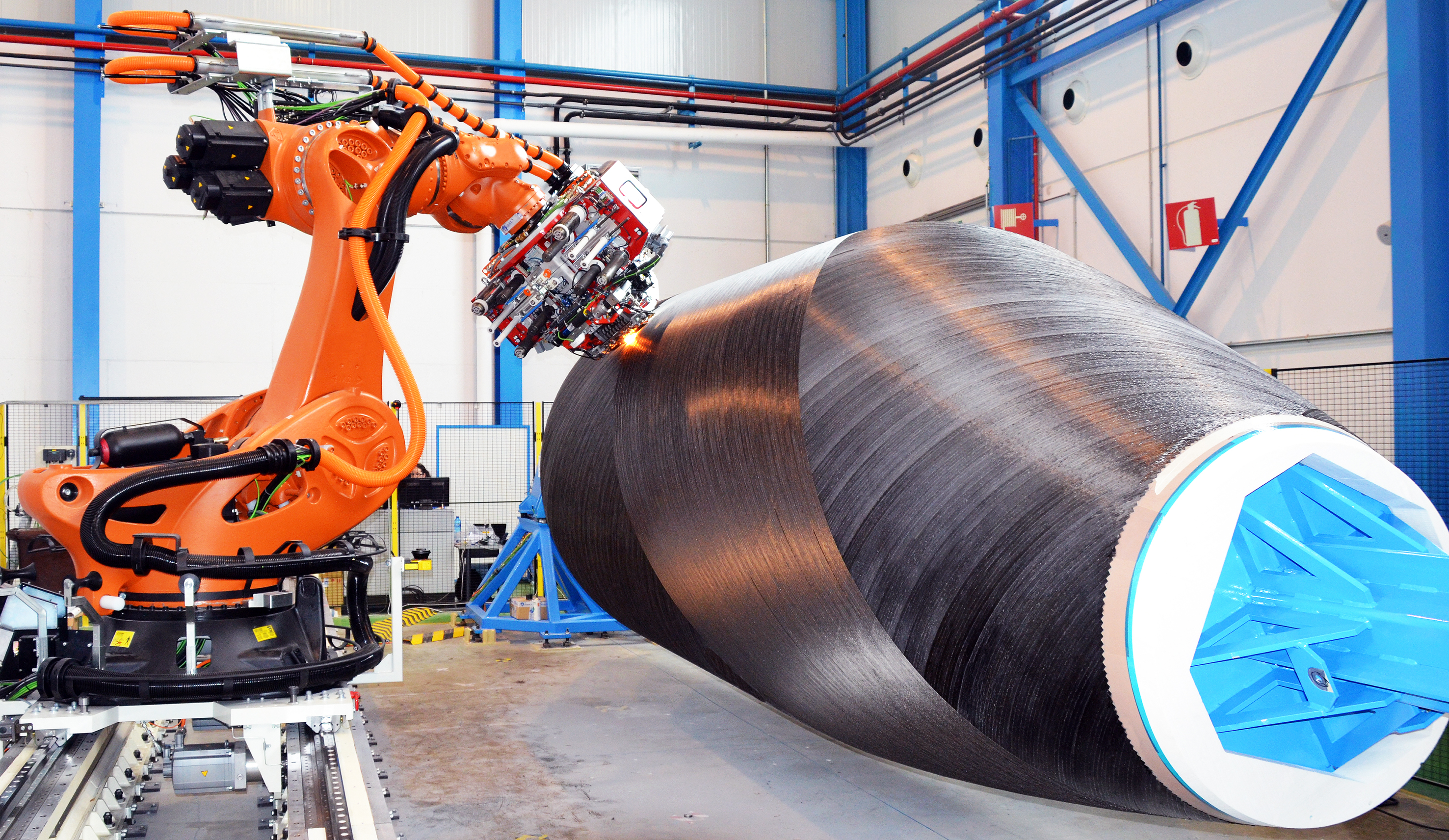
Step 11: This actual photo shows dry fiber placement over the rings, to create the demonstrator’s skin. In actual practice, copper mesh for lightning strike protection would be added as well. Following standard caul placement, bagging, infusion and skin cure, a robotic machining station cuts out the door and window openings.
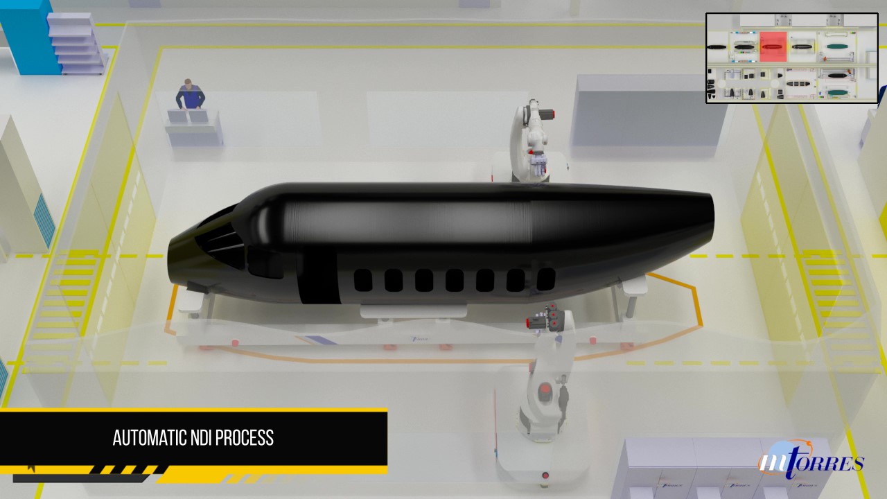
Step 12: At the end of the final body join, automated nondestructive inspection occurs. Following this step, the fuselage is outfitted with its interior and any remaining systems, and is ready for shipment.
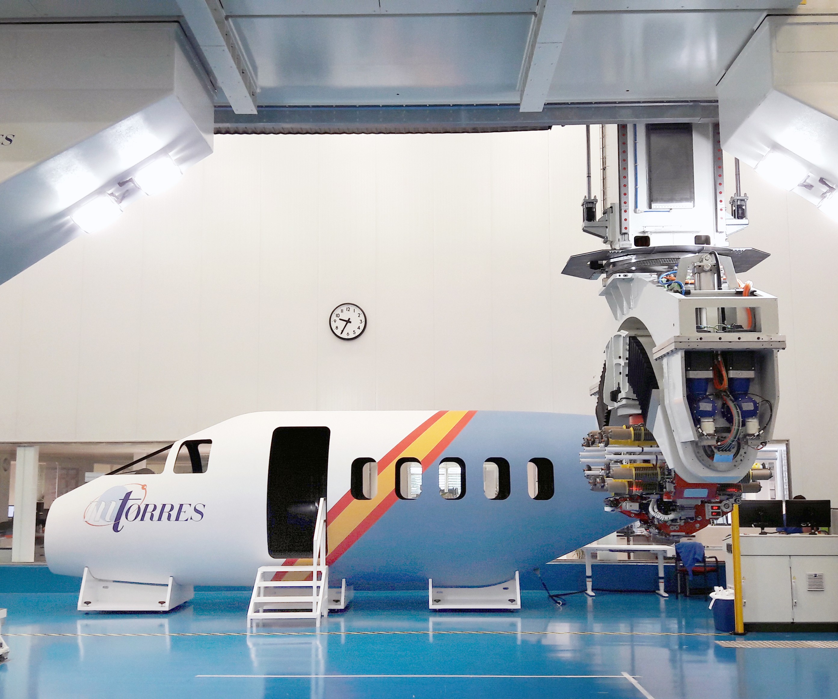
Fig 2: The product and the process
The finished demonstrator inside the cleanroom manufacturing environment in which it was fiber-placed. Multiple customers have expressed interest in the automated factory concept as well as the fuselage’s design principles.


Everyone is talking about “one-minute” cycle times as a means to increase composites’ acceptance in the automotive industry. But that drive for shorter production cycles through development of more time-efficient materials and processes is no less important in the aerospace world. As aircraft build rates continue to ramp up, the need to control the cost of aerocomposites is critical as well. Toward that end, changes are underway in design, materials and processes.
A new aircraft structure production concept, called Torreswing, aims to bypass incremental development and, instead, target disruptive change in fuselage and wing fabrication technology by eliminating conventional tooling and the use of fasteners during automated fabrication of large, one-piece monocoque structures. Developed by machinery manufacturer MTorres (Torres de Elorz, Navarra, Spain), this radical departure from the manufacturing norm made its debut in 2017. It was recognized with a JEC Innovation Award in the category Aerospace Process at the 2018 JEC World exhibition in Paris, and was exemplified by a demonstration fuselage on display at the MTorres stand.


CW had the opportunity to interview MTorres’ Integrated Assembly group’s key account manager for the technology, Luis Enrique de la Iglesia y Gotarredona, and R&D business development manager Iñigo Idareta, and thus got this exclusive look at how the process works.
Factory of the future
Composites’ use on commercial and general aviation (GA) aircraft has increased significantly over the past decades, and so has the use of automation in aerospace fabrication. Obvious examples are the use of automated fiber placement (AFP) to make the fuselage barrels of the Boeing 787, the wings of Airbus’ A350, the wing spars and wings of Boeing’s 777X, and, more recently, the FLEXMONT project’s process for robotic assembly of Airbus vertical tail planes (see “The future of CFRP aerostructures assembly”). That said, a great deal of touch labor is still required to assemble a finished plane.
“The basis of the Torreswing process is a simple and easy-to-automate concept,” said De la Iglesia y Gotarredona, while illustrating the Torreswing process using two animated videos on display at the JEC World event, showing manufacturing steps that eliminate nearly all hand labor.
“A series of ‘elemental parts’ [Fig. 1] are made first.” He explained. “Those elemental parts then become the molds on which a monocoque fuselage is created.” In the case of an aircraft fuselage, those elemental parts include multiple carbon fiber composite frames, or rings, sized to the aircraft, and flat floor panels. Finished frames are butted together, adhesively bonded, and the floors placed inside the rings, to form the fuselage “skeleton” that is overwound via fiber placement to form the outer skin. The concept simplifies manufacturing and eliminates the metal fasteners that would otherwise join fuselage sections, or attach skin to stringers/frames. Wings and tail also would be made in a similar automated process, but no information is yet available for the wing process, which is still under development. “The current concept uses dry fiber and resin infusion, born from our experience in wind blades,” says Idareta, but he points out that “it can accommodate prepreg, or thermoplastic materials, as the customer wants.”
In the automated factory scenario, a small army of industrial robots and positioners shuttle parts from one station to the next, in a U-shaped workflow. “The factory and manufacturing concepts have increased the level of automation and reduced the number of required tasks, and it’s certainly doable today with the MTorres integration machines,” claims De la Iglesia y Gotarredona.
Assembling some essentials
Phase I begins with the elementals. In the ring layup line, which runs parallel to the floor layup line (See Step 1), a robot transfers a metallic, collapsible ring mandrel, customized to the customer’s aircraft fuselage shape and size, onto a rolling positioner robot, equipped with a rotating headstock. The positioner moves into the next station, between two stationary MTorres AFP heads mounted on robotic arms, that quickly lay dry carbon fiber tape onto the mandrel surface, which is grooved on the outside (Step 2). More on the purpose for the grooves, below. The layup, as proposed in the concept, has 0°, 90° and ±45° plies, but can be optimized for each application. MTorres has developed its own dry carbon fiber tape for the process, using carbon fiber from a proprietary source, to which it adds a heat-activated thermoplastic binder, which functions both to give the tape some tack during layup and to enable infusion performance.
Note that, on the front and back side of each ring, a flat plate is fiber placed (Step 3), to create support for the floor panels. Next, the rings are prepared for resin infusion, with technicians bagging the layups and adding resin feeder lines. After bagging, a robot places the bagged rings on an automated transfer jig, which moves the rings to the infusion station, manned with technicians who oversee the resin infusion and vacuum.
Meanwhile, at the floor layup line, three robotic arms work in concert to produce the flat floor panels. The first robot lays a 0°/90° laminate on a flat table mold, which is attached to a moving floor or jig feed line. The moving line takes that layup to a second station, where a robotic arm equipped with a pick-and-place end-effector places foam core over the laminate. At the next station, a third robot places a 0°/90° laminate skin over the core. The thickness and ply architecture of the panels are customized to the requirements of the application, says the company. Panels are largest, and square in shape for the middle part of the fuselage, but are produced in smaller, tapered shapes for the narrower tail and nose areas.
The completed, flat, cored panels are vacuum bagged and resin infused. At this point, small positioning robots automatically transfer the bagged and infused rings and floor panels to an oven for curing.
After cure, positioning robots ferry the cured parts to the next station, where the parts are unbagged and then placed in a workcell where a robotic arm with a cutting head performs machining steps. These include cutting holes in the flat plates on each ring (which will support the floor), to reduce weight and allow for wiring. The edges of the floor panels also are trimmed. As machining concludes, a robot extracts the mandrels from inside the cured rings and carries them back to the start of the ring layup line. Each part undergoes robotic nondestructive inspection (NDI) and then is carried to a final station where human inspectors look over each part and perform any remaining tasks prior to the next phase.
Flexible “flying mandrel”
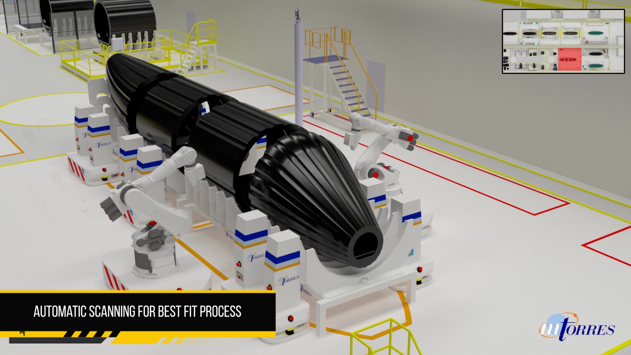
Completed elementals are assembled in a “final body join” process, within a second manufacturing hall. At the barrel assembly station, the completed rings are robotically loaded onto an alignment tool, from a transfer jig. Two robots take up positions on each side of the alignment tool and scan the rings to document their exact sizes, so that the best fit between them can be determined. Then, having determined the locations of gaps, the robots apply adhesive in greater or lesser amounts depending on the degree of misfit, and the alignment tool pulls the rings together to form a barrel, and ensure complete contact with the adhesive (Step 7).
At the next station, the bonded barrel is placed on another jig by a positioning robot, where the two scanning robots scan the floor panel and the floor support plates within the barrel for best fit. While one robot uses an end-effector to pick up the floor panel, the second applies more adhesive to bond the floor panel to the support plates. As each fuselage segment is bonded and finished, human workers install wiring, ducting and other systems beneath the floor panels or inside the fuselage space.
This process is repeated for each fuselage segment, from nose to tail, to form a structural assembly of rings and floors — in essence, a full-sized mandrel for the next step of the process (Steps 8-9). “No large metallic tooling is necessary. The carbon fiber elements, in any size or shape, act as mandrels or tools, and the remainder of the part is fiber-placed over those elements,” explains De la Iglesia y Gotarredona. And the use of adhesively bonded segments easily enables the use of larger, smaller and/or a greater or lesser number of segments necessary to create a fuselage of the length needed for a particular aircraft.
Rings replace stringers
At the next station, automated positioners place the structure in a station with rotating headstock and tailstock fixtures, and an MTorres fiber placement head begins placing dry fiber over the assembled rings to form the fuselage skin. The first ply is placed down into the grooves created by the rings, noted above (Step 10). Then, a robot places pieces of “filler” material into the grooves. Filler material could be foam, which could remain in place as insulating material, or another type of material that would be removed after cure of the skin, perhaps a dissolvable material, explains Idareta.
Says De la Iglesia y Gotarredona, “The grooves essentially act as stringers on the outside of the fuselage, when overwound with a skin to form a hat structure. This is a huge departure from today’s aircraft construction, which has longitudinal stringers and circular frames, typically made separately and installed by hand on the inside of the skin. The overwound grooved rings replace all of that.” He adds that in existing composite aircraft, MTorres calculates that stringers account for 30% of the material but 70% of the cost.
When the overwinding is complete — a five-layer laminate (Step 11), for a total thickness of less than 4 mm in the skin/ring structure, was used in the demonstrator (again, customizable for a specific aircraft) — cauls are placed, the entire fuselage is bagged, the skin is infused with resin and oven-cured. After cure, the fuselage is transferred to a machining cell, where a robotic head cuts window and door openings. Then it is taken to the final station before shipment (Step 12), where workers manually install required electronics and avionics, and add seating.
Is this the future?
The Torreswing process is designed to eliminate virtually all metallic fasteners and rivets, a significant weight savings over today’s aircraft, says the company. The adhesive used to bond the elemental rings, says Idareta, would be equivalent in weight to the shimming material used on conventionally built aircraft. And, with the high degree of robotic automation, cycle time and touch labor would be significantly reduced, resulting in process simplification and much lower manufacturing costs. For example, he adds, the number and size of part-specific tooling and the time needed for part production on that tooling would reduce manufacturing costs significantly. Other advantages include elimination of the autoclave in favor of oven cure, and use of dry fiber, reducing material cost.
Although it’s a TRL 6 project, only one demonstrator has been built so far — the fuselage shown at JEC, using equipment similar to that depicted in the step photos. But there are plenty of opportunities for a first customer trial. “There are a lot of proposals for new aircraft today, and we see a big market, which we believe would justify this factory concept.” Idareta acknowledges, of course, that certification of a bonded structure could be a challenge, given a regulatory environment that currently requires redundant fasteners for certification. “Our point of view,” he says, “is how to enable the plane of the future using the factory of the future. We’ve designed for automation, not just for manufacturing.” He also notes that a number of composites manufacturers in other industries are showing interest in the automated factory concept behind the innovative aircraft design, taking care to point out, “We’re not aircraft designers, we’re factory automation specialists.”


.jpg;maxWidth=300;quality=90;format=webp)

Related Content

MFFD thermoplastic floor beams — OOA consolidation for next-gen TPC aerostructures
GKN Fokker and Mikrosam develop AFP for the Multifunctional Fuselage Demonstrator’s floor beams and OOA consolidation of 6-meter spars for TPC rudders, elevators and tails.
Read More
Materials & Processes: Resin matrices for composites
The matrix binds the fiber reinforcement, gives the composite component its shape and determines its surface quality. A composite matrix may be a polymer, ceramic, metal or carbon. Here’s a guide to selection.
Read More
Materials & Processes: Composites fibers and resins
Compared to legacy materials like steel, aluminum, iron and titanium, composites are still coming of age, and only just now are being better understood by design and manufacturing engineers. However, composites’ physical properties — combined with unbeatable light weight — make them undeniably attractive.
Read More
Materials & Processes: Tooling for composites
Composite parts are formed in molds, also known as tools. Tools can be made from virtually any material. The material type, shape and complexity depend upon the part and length of production run. Here's a short summary of the issues involved in electing and making tools.
Read MoreRead Next

CW’s 2024 Top Shops survey offers new approach to benchmarking
Respondents that complete the survey by April 30, 2024, have the chance to be recognized as an honoree.
Read More
From the CW Archives: The tale of the thermoplastic cryotank
In 2006, guest columnist Bob Hartunian related the story of his efforts two decades prior, while at McDonnell Douglas, to develop a thermoplastic composite crytank for hydrogen storage. He learned a lot of lessons.
Read More
Composites end markets: Energy (2024)
Composites are used widely in oil/gas, wind and other renewable energy applications. Despite market challenges, growth potential and innovation for composites continue.
Read More