
Revisioning the Viper: Clamshell hood challenge
Autoclave-cured carbon-fiber prepreg hood/fender combo proves as technically formidable as it is visually stunning.

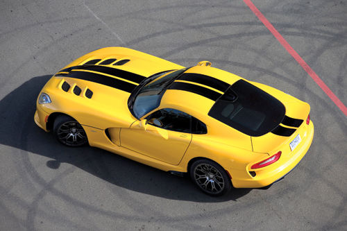
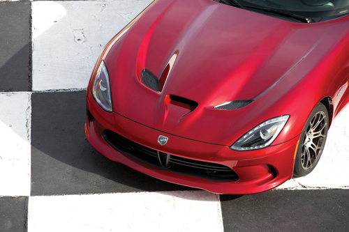
When Chrysler Group LLC brought back its iconic Viper for the 2013 model year, the development team’s aggressive yet sophisticated styling strategy yielded two configurations: One for the core SRT version (bottom), an aggressively sporty, “raw” look that exemplifies traditional “Viper values” and another (top) for the GTS variant, with features and appointments found in grand-touring cars. Each features a unique hood outer skin. Source; Chrysler Group LLC
The Viper GTS variant, with features and appointments found in grand-touring cars. Source; Chrysler Group LLC
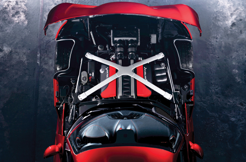
The new Viper’s classic look is enhanced with a forward-hinged hood that opens toward the front bumper and offers an unobstructed view of, and access to, the engine compartment. Source: SPE Automotive Div.
Step 1: A day before they are scheduled to be used in production, plies of CFRP prepreg are cut and assembled into kits, then refrigerated. Source: Plasan Carbon Composites

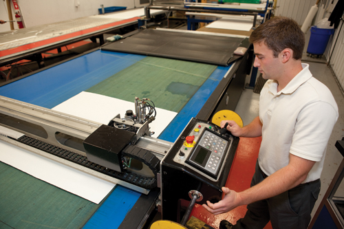
Step 2: As work begins on layup for a panel on the clamshell hood, the layup instructions for that part are loaded into the laser-guidance system. Also, retroreflective targets with cross-hairs are shot down at the lift table to calibrate the laser prior to start of layup. Source: Plasan Carbon Composites
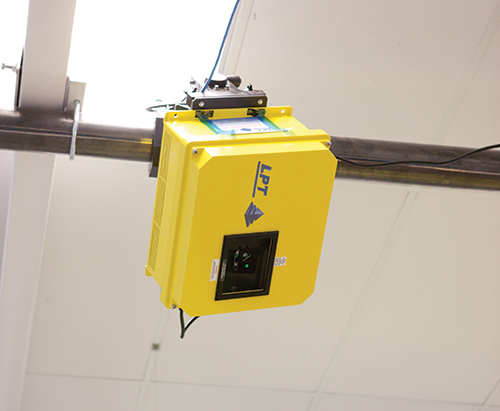
Step 3: A laser projection unit is suspended from the ceiling over each work area where the clamshell hood panels will be layed up. Source: Plasan Carbon Composites
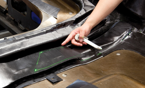
Step 4: The system sequentially projects a green laser outline in the exact shape of the next ply that should be laid down in its specific target location, providing a poka-yoke (mistake proofing) mechanism as well. Source: Plasan Carbon Composites
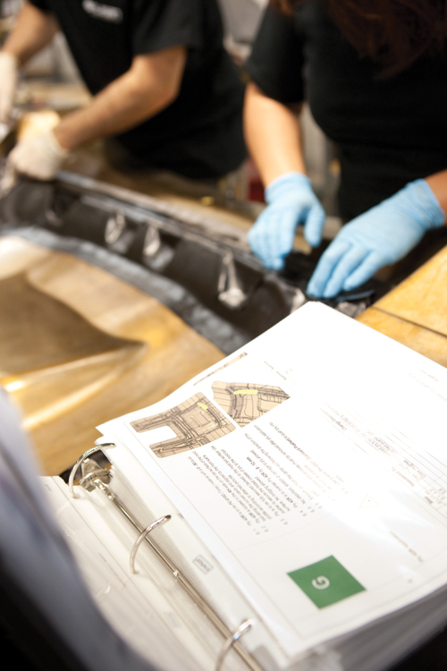
Step 5: For reference, the work instruction/ply book is never far away. Source: Plasan Carbon Composites
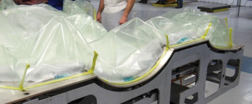
Step 6: Once layup is complete, the part is bagged and prepped for the autoclave cycle. Source: Plasan Carbon Composites
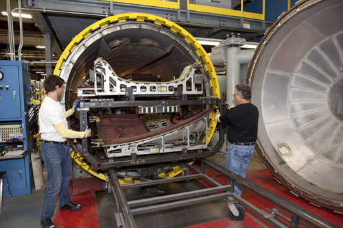
Step 7: The NVD clamshell hood tools are so large that special racking had to be developed to move the bagged parts into and out of the autoclave. In fact, these tools barely fit in Plasan’s 30 ft/9.1 m autoclave. Source: Plasan Carbon Composites
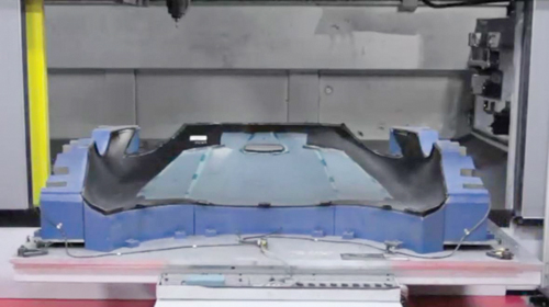
Step 8: Once the autoclave cycle is complete and parts are cooled and demolded, both inner and outer panels are sent for routering. Source: Plasan Carbon Composites
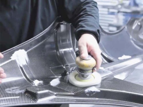
Step 9: Next, inner panels with visible carbon weave are buffed and polished to a high luster. Source: Plasan Carbon Composites
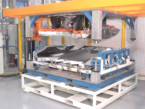
Step 10: Once trimmed, inner and outer panels are brought together in a fixture and adhesively bonded and cured via hot-air impingement. Source: Plasan Carbon Composites
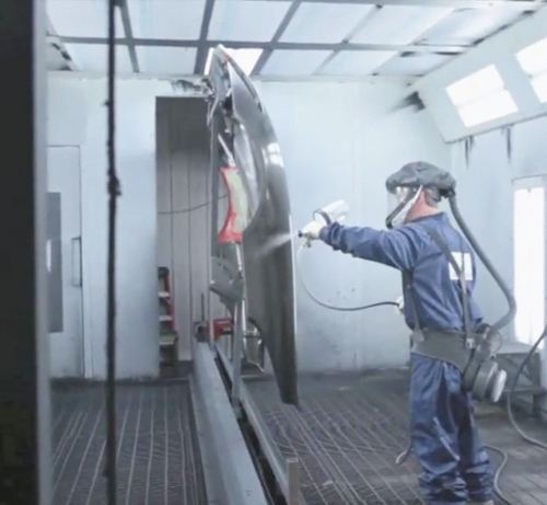
Step 11: After that, the complete assembly is masked and then paint primer is applied to the outer panel. Source: Plasan Carbon Composites
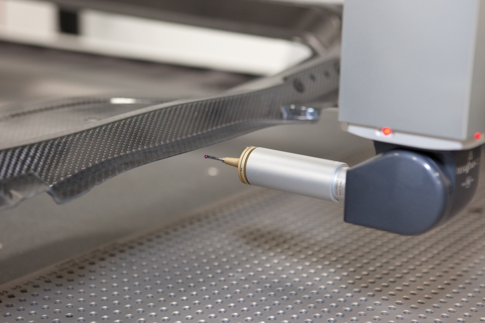
Step 12: The final step before the complete assemblies are shipped out to another supplier for paint is inspection/measurement to ensure dimensionality and surface quality. Source: Plasan Carbon Composites

Measuring almost 2m by 2m (6.6 ft by 6.6 ft), the bonded clamshell hood assembly consists of a painted one-piece CFRP outer panel and two unpainted/polished CFRP interior panels with visible weave. Source: SPE Automotive Div.


When Chrysler Group LLC (Auburn Hills, Mich.) brought back its iconic Viper supercar under its new SRT (Street & Racing Technology) brand, after a two-year absence, the development team wanted it to return with more power and performance, superior craftsmanship, comfort features and innovative technologies than ever before. Moreover, the Viper design studio wanted to make a big statement on this 5th-generation Viper with aggressive yet sophisticated styling. A major step toward that goal was the visually stunning but technically challenging clamshell hood/fender assembly, produced in prepreg autoclave-cured carbon fiber-reinforced plastic (CFRP).
Unveiled on April 4, 2012, at the New York International Auto Show (New York), the 2013 Viper sports chassis enhancements that boost torsional stiffness by 50 percent. That and a lightweight skin of composites (more than 50 percent of the vehicle’s exterior) and aluminum enhance high-speed stability, improve aerodynamics and reduce curb weight by more than 100 lb/45 kg, giving the 2013 Viper the best power-to-weight ratio in Viper history.


New look, new challenges
The new Viper sports the same low stance and extreme cab-rearward proportions that have traditionally defined this mid-engine two-seater, and the car’s classic look is enhanced by a return to a traditional Viper clamshell hood, but forward-hinged (see photo, at left) to provide an unobstructed view of the engine compartment, including the 8.4-liter/513-in3 V-10 engine and the tops of the front wheels. The hood’s aggressive sweep, prominence and high aesthetic, inside and out, make it a key visual focus, but its sheer size — nearly 2m by 2m (6.6 ft by 6.6 ft) — and the fact that it was to be molded in CFRP laminate raised a host of manufacturing and tooling challenges for Tier 1 molder Plasan Carbon Composites (PCC, Bennington, Vt.) and toolmaker Weber Manufacturing Technologies Inc. (Midland, Ontario, Canada). The clamshell unites the hood and fenders, and it features a painted, one-piece outer panel bonded to a polished (unpainted/visible-weave) two-piece inner panel (no cores are used). The studio wanted the outer panel molded as a unit not only to prevent the read-through (aesthetics-spoiling “shadows”) that occurs in painted parts with bondlines but also to avoid the cost of multiple tools and extra finishing associated with bonded parts.
“We favored the functionality and styling heritage of combining hood and fenders into one large part,” says Mike Shinedling, Chrysler’s Viper launch manager, but he notes, “There were also weight and finishing advantages of a single-piece outer panel clamshell. Since our projected peak volumes [2,500 units/annually] meant that we were going to have to make multiple hood molds anyway, we took advantage of that and designed two different outer panel styles.”
There are, in fact, two models of the 2013 Viper: The core SRT version is aggressively sporty, “raw” and exemplifies traditional “Viper values,” while the GTS model has more of the features and appointments found in grand-touring cars. Although both hoods are similar in shape, the SRT version has six air extractors to cool the engine during operation and the GTS model has only two. Both hoods also feature an engine air intake scoop, which proved to be the most difficult feature to mold on the entire car. Holes for air extractors are molded in rather than cut out of the hood’s solid laminate. The studio believed that molded-in openings would provide a better styling interface for bezels, because GTS-model air extractors have a flush gap, while those on SRT models are subflush.
Not just for show, these fully functional scoops perform different tasks. Scoops on opposite sides of the die line are designed with opposing drop angles, so the front scoop pulls cool air into the engine while the others vent hot air from the radiator up and out. Opposite draw angles in the tool made demolding a challenge, particularly in a one-piece design with rigid CFRP, because they must be pulled in opposite directions during removal.
Another challenge was maintaining gap tolerances on the hood side-to-side and point-to-point because the assembly mounts to a magnesium-and-steel frame on the car body, and meets the bumper fascia, aluminum side sills, and door — parts made from materials with coefficients of linear thermal expansion (CLTEs) much higher than CFRP’s very low value.
Also problematic was the fender curvature, which made layup in these sections extremely difficult. Worse, a full return flange runs the entire periphery of the outer panel and forms the finished edge of the composite part, much like a rolled and hemmed edge does on stamped-metal parts. However, because the flange measures between 3 and 4 mm (0.12 and 0.16 inches), it provides a significant undercut that’s hard to lay up and even trickier to demold. In fact, during brainstorming sessions with Chrysler early in the program, PCC representatives told the automaker that the flange’s tight radius might make the part impossible to manufacture. “We pointed out that this flange’s radius was less than 2 mm [0.08 inch], which within the automotive carbon composites industry would be considered substandard and, therefore, likely to lead to breakage of fiber bundles, recounts Gary Lownsdale, PCC’s chief technology officer. “Normally, in our industry, 3 mm [0.12 inch] is considered the minimum you can go without getting fiber bridging and resin-rich edges.” Although CFRP laminate can be molded to near-net shape, PCC deliberately overmolds to ensure that edges have the right resin/fiber mix to avoid dry spots or resin-rich areas that could fail prematurely. “Chrysler asked us to go back and reconsider, but early on, there were only two of us who believed this part could be made,” recounts Lownsdale. “We knew we had considerable technical hurdles to clear.” Ultimately, the entire engineering team — automaker, molder and toolmaker — “knuckled down and found a way to make it work,” he adds. “We did this through tooling concessions, developing new technologies and, as a last resort, styling concessions.”
Fortunately, PCC often looks to other industries to benchmark new projects, especially when it tackles a part not previously done in automotive, and that’s where the team found some interesting solutions. For example, predictions indicated that the outer panel could be pulled off the tool, but that the return flange from the outer panel to the inner panel insertion would cause interference — one reason the inner panel was, in the end, produced in two pieces. Getting the die pull angles just right in such a tight geometric pattern so that the hood and side scoops could be separated from the tool also made mold design a challenge, but Weber met it by developing additional, hand-placed inserts for these sections.
Weber used CAD data to produce three single-sided hood outer tools and two hood inner tools, using the nickel-vapor deposition (NVD) process. The inserts for tricky areas were machined from P20 steel, including the air extractor openings. When Weber machined the blocks of aluminum that would be used to create the mandrels for the outer-panel NVD tools, they were so large that they barely fit within the work envelope of the company’s 5-axis CNC machine. Further, the fully vacuum-bagged outer part in its tool barely fits in PCC’s 30 ft/9.1m autoclave in Bennington, where the parts are produced. Getting bagged parts into and out of the pressure chamber requires careful racking technique and two technicians to avoid damaging the vessel’s liner and vacuum lines.
Notably, given the complexity of the assembly, no prototype tooling was produced. A series of “engineering splashes” — parts made with temporary composites tooling, which can be pulled off clay models, REN (wood/epoxy composite) planks or even another part — was used to produce parts that could be analyzed in Chrysler’s wind tunnel, but no conventional stepped tool-build process was necessary, a fact that sped development and reduced costs. Shinedling says that the kickoff of surface geometry through to the first trials on production tools spanned only 16 to 18 weeks.
Aerospace material insights
Materials selection for this project drew from supplier input, Shinedling’s automotive experience, and the aerospace background of colleague Howard Coopmans, Viper project responsible, Street & Racing Technology. “We had a lightweight objective on a large part that had to be toolable,” notes Coopmans, who, as a former Boeing engineer, well understood strength and stone-chipping issues around such a large part and suggested a move to a tougher resin system in the prepreg. The team selected unidirectional prepreg supplied by Toray Composites America Inc. (Tacoma, Wash.) for the inner layers of all panels and the outer layer of Class A painted surfaces, and used 2x2 twill-weave fabrics for the face layers of polished/unpainted inner panels. Although they are technically not aerospace-grade materials, they are impregnated with G83C epoxy resin, optimized for strength, cost, and processability, and supplied at standard 186-g/m2 (5.49-oz/yd2) areal weights. Their greater ultimate strength permits production of thinner, lighter panels with minimal surface defects and high smoothness. They meet the team’s high aesthetic requirements for both painted hood outers and polished hood inners. The ply counts vary depending on panel and location but, typically, six layers are used on the outer panel (except in thicker load-bearing areas around latches and hinge) and feature up to 15 plies on sections of the inner panel. As designed, the outer panel has a nominal 1.2-mm (0.05-inch) wall thickness, while the inner panel’s thickness varies from 1.45 to 3.25 mm (0.06 to 0.13 inches) to satisfy global panel stiffness and slam/durability requirements while still minimizing assembly mass.
Given the size and complexity of the part kits, and the fact that some plies are cut at ±45o instead of standard 0o/90o, PCC worked diligently to maximize cutting efficiency via software and design of experiments (DOE). The work was done at PCC by senior research engineer James Salerno and manufacturing engineer Neil Sbardella. “We conducted extensive DOEs of kit lot sizes and combinations, and we improved kit-cut efficiency dramatically,” explains Salerno. “Currently, we’re well over 70 percent efficiency for the hood nests. The large and complex nature of the plies used on these parts made this a very difficult achievement.” Salerno used JetCam CAD/CAM nesting and materials management software (from JETCAM International, Monaco) in conjunction with CATIA CAD software (from Dassault Systèmes, Vélizy-Villacoublay, France) and Simulayt AFM advanced fiber modeler (Simulayt Ltd., Woking, Surrey, U.K.). Kits are typically cut a day ahead of production and refrigerated.
Layup speed and efficiency
Early in development, technicians were forced to do blind layups in certain areas of the part — even when they bent over the tool, they couldn’t see where they placed plies, owing to the tool’s size and curvature. To improve confidence in layup accuracy, Lownsdale borrowed a layup technique he’d learned while he was CEO of Mastercraft Boat Co. (Vonore, Tenn.), because the hood curvature is similar to that of a boat hull: Pairs of technicians work on opposite sides of the tool, each directing the other as he/she hand-places the plies. This “spotting” technique was used for many months during the development phase, but the ply schedule was so complex that as PCC neared the PPAP (production part approval process), the R&D team added a tool borrowed from aerospace — a ceiling-mounted, laser ply-placement system that sequentially projects green outlines in the precise shape and at the exact location where each ply must be laid down.
Typically, three technicians now take 90 minutes to lay up each hood panel, then carefully wheel the bagged parts to the autoclave where they go through a 110-minute cure cycle. Although the cycle could be faster, it has, thus far, been paced to match other steps in the production sequence. Cured parts are carefully wheeled out, disposables are removed, and they undergo a power-cooling cycle before a demolding sequence that employs a combination of lifters and other, proprietary techniques designed to remove parts without damaging their Class A surfaces. Demolded parts are trimmed, bonded and finished. For painted parts, primer is applied to seal the edges and parts are shipped on special racks for painting elsewhere. Inner and outer panels are bonded with Pliogrip structural adhesive (Ashland Performance Materials, Dublin Ohio) and cured in a hot-air impingement bonding fixture.
The bare, bonded hood assembly weighs only 36.62 lb/16.61 kg, a 43 percent mass reduction vs. equivalent parts on previous Vipers made from metal and sheet molding compound (SMC). The hood’s low mass contributes to the vehicle’s lower center of gravity, which improves handling, cornering and braking stability. Shinedling notes that when first-time customers open the hood, they’re shocked at how little it weighs.
By all measures, the 2013 Viper already is a success. Customers love it, the car has won a number of prestigious awards, and Chrysler is well on the way to meeting target volumes its first year.


.jpg;maxWidth=300;quality=90;format=webp)


Related Content

Thermoplastic composites welding: Process control, certification, crack arresters and surface prep
More widespread use of welded composite structures within a decade? Yes, but further developments are needed.
Read More
CFRTP enables better, greener smartphones
Carbon Mobile’s “monocoque” design eliminates separate case, cover and frame, better protects electronics and simplifies disassembly.
Read More
Multi-material steel/composite leaf spring targets lightweight, high-volume applications
Rassini International was challenged by Ford Motor Co. to take weight out of the F-150 pickup truck. Rassini responded with a multi-material steel/composite hybrid leaf spring system that can be manufactured at high volumes.
Read More
Jeep all-composite roof receivers achieve steel performance at low mass
Ultrashort carbon fiber/PPA replaces steel on rooftop brackets to hold Jeep soft tops, hardtops.
Read MoreRead Next

CW’s 2024 Top Shops survey offers new approach to benchmarking
Respondents that complete the survey by April 30, 2024, have the chance to be recognized as an honoree.
Read More
Composites end markets: Energy (2024)
Composites are used widely in oil/gas, wind and other renewable energy applications. Despite market challenges, growth potential and innovation for composites continue.
Read More
From the CW Archives: The tale of the thermoplastic cryotank
In 2006, guest columnist Bob Hartunian related the story of his efforts two decades prior, while at McDonnell Douglas, to develop a thermoplastic composite crytank for hydrogen storage. He learned a lot of lessons.
Read More