


Multi-functional fuselage panel
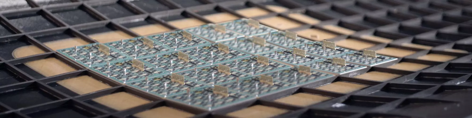
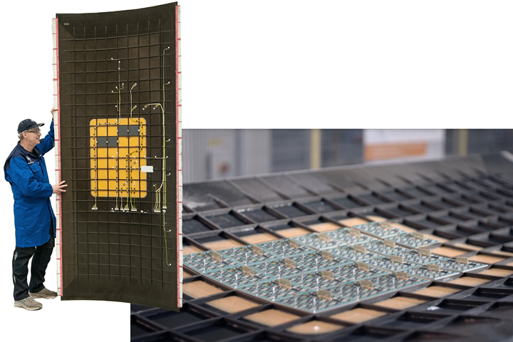
The NLR-led ACASIAS project demonstrated a 1.2 x 3-meter fuselage panel into which a 4 x 6 array of Ku-band antenna elements (inset) was integrated. The array sits within a glass fiber composite “window” in the outer skin for RF transparency and is supported within an orthogrid of CFRP panel stiffeners. Photo credit for all images: NLR
A key challenge for cleaner air transport is to reduce aerodynamic drag on aircraft surfaces. An obstacle to this, however, is the increased need for Ku-band antennas to provide in-flight internet access, which are positioned within large, protruding radomes on top of the aircraft.
The Horizon 2020 project “Advanced Concepts for Aero-Structures with Integrated Antennas and Sensors” (ACASIAS, June 2017-Nov. 2020) aimed to address this issue and to reduce aircraft fuel consumption by integrating antennas into the fuselage, winglets and tail. Led by the Netherlands Aerospace Center (Royal NLR, Marknesse, Netherlands), the 11-partner ACASIAS consortium developed new antennas and also new glass and carbon fiber-reinforced polymer (GFRP, CFRP) composite structures to integrate these antennas into the airframe.


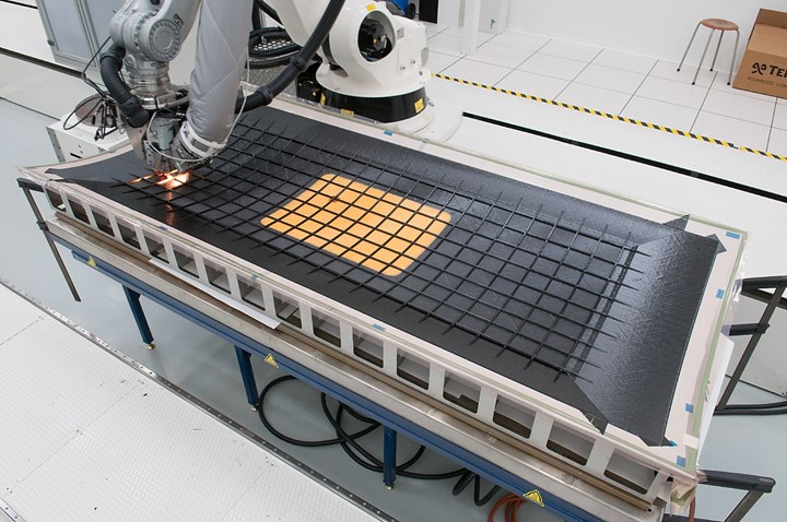
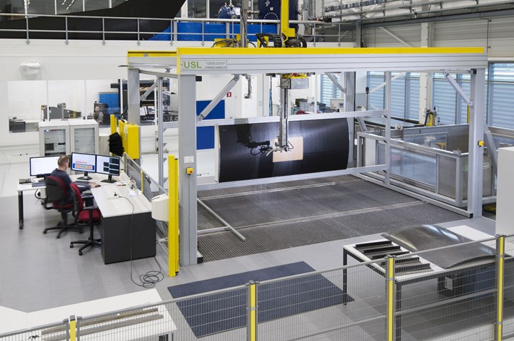
This article explores NLR’s demonstration of a 3 x 1.2-meter fuselage panel, made using a Coriolis Composites (Quéven, France) automated fiber placement (AFP) machine and 6.35-millimeter-wide HexPly 8552 unidirectional (UD) prepreg tape (Hexcel, Stamford, Conn., U.S.) comprising Hexcel AS4 carbon fiber and 350°F/177°C cure toughened epoxy resin. AFP was used to produce the fuselage skin and its integrated grid of narrow (one tape-width) stiffeners. To prevent buildup at the intersections of the stiffeners during AFP layup, half of the tapes were cut in one direction and half in the opposite direction.
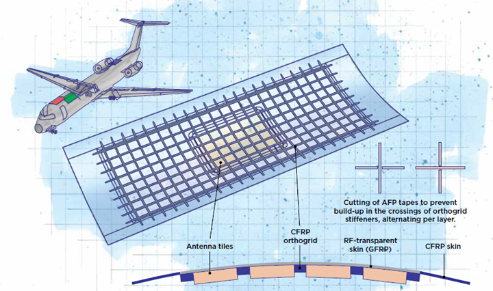
ACASIAS antenna-integrated fuselage panel. Image illustrated by Susan Kraus.
A novel approach was also adopted for the tooling. A molded reusable vacuum bag was used to replace the roughly 500 metal tooling blocks required for conventional isogrid manufacturing. Isogrids are one-piece, grid-stiffened structures most commonly used in payload adapters and other tubular or conical spacecraft components. The reusable vacuum bag was created by spreading a room temperature-cure silicone onto a CNC-machined aluminum pattern of the stiffener grid, enabling autoclave cure without the need to place, remove and clean tooling blocks.
The completed integrated structure also eliminated bonding and mechanical fastening of stiffeners and used Solvay (Alpharetta, Ga., U.S.) FM906 S2 glass fiber UD prepreg tape to create a radio frequency-transparent “window” for the antenna elements.
Orthogrid-based demonstrator
“Three departments in NLR were involved in this project,” says NLR project manager Peter Nijhuis. “One group developed the phased array antenna and electronics, my department developed the composite design and manufacturing and then our test department did all of the large panel testing.” The design of the ACASIAS fuselage panel demonstrator was based on loads for a forward crown section of a Fokker 100 single-aisle aircraft and developed in collaboration with the International Center for Numerical Methods in Engineering (CIMNE, Barcelona, Spain).
When completed, the ACASIAS antenna comprised 24 antenna tiles (4x6 grid) where each tile contained an 8x8 grid of very small antenna elements.
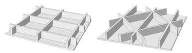
An orthogrid (left) was chosen versus a more traditional isogrid (right) for the stiffener pattern.
The antenna to be incorporated into this crown section comprised 24 tiles measuring 100 x 100 millimeters (see opening image), each containing an 8 x 8 grid of very small antenna elements. Typical composite fuselage panels do use stiffeners, including longitudinal stringers and transverse ring frames. For this panel, however, the idea was to exploit the lightweight design of isogrids, which could also serve to contain the antenna cells. Although the traditional triangular pattern of isogrids is better for shear loads, this forward crown section of the fuselage sees relatively low shear loads, says Nijhuis. Thus, a rectangular-patterned orthogrid concept was feasible and would better fit the square antenna tiles.
The stiffener grid was designed to provide redundant load paths to carry tensile, compressive and shear loads while the skin would only need to sustain cabin pressure loads. Typically, a damage-tolerant approach for composite aircraft structures allows a maximum of 3,000 microstrain, Nijhuis explains. “By using this grid structure, strains up to 6,000 microstrain would be possible.” Thus, this configuration allowed a different design philosophy and the potential for significant weight reduction.
At the edges of the panel, the stiffeners were tapered and the skin thickness was increased to enable introduction of loads during testing, which included a combination of pressure, axial and circumferential loads applied via a specialized test rig. These test results were used to validate the finite element analysis (FEA) model used for the design.
Outer skin plus radome
“In the area of the antenna elements, the panel’s outer skin must be transparent for the electromagnetic signals to pass through,” says Nijhuis. “So, here is where we used the S2 glass prepreg. However, we wanted to keep the stiffness as close as possible to the CFRP skin in the rest of the panel. Because S2 glass fiber is lower in modulus than carbon fiber, we had to increase the thickness.” The CFRP skin was roughly one millimeter thick, while the glass fiber “window” (radome) was 2.1 millimeters thick. The CFRP laminate was produced using NLR’s Coriolis AFP machine, which applied eight tows of 0.25-inch-wide tape. “We chose the Hexcel tapes,” says Nijhuis, “based on what was readily available that worked well in the AFP machine and also gave good properties." The GFRP laminate was actually placed by hand, but could be laid using AFP.
He continues, “For the loads on this part of the fuselage, the CFRP skin could actually be very thin. However, this is not practical for impact resistance. To meet this need, we used basically a quasi-isotropic laminate comprising six plies but with more of the plies oriented at ±45 degrees and only one ply each at 0 degrees and 90 degrees.”
Still, to test this new design approach and potential for higher strain levels, the CFRP skin thickness was a bit thin for normal aircraft, notes Nijhuis, “but there are areas such as fairings and blended wing body designs where this could be a good option. Also, the strain for this skin design, even with only six plies, was still quite low. So, the higher strain levels possible were not actually reached.” This first design, however, was sufficient to test NLR’s ideas for how to manufacture multifunctional fuselage panels more efficiently.
AFP orthogrid stiffeners
After placing the CFRP skin and GFRP radome/window, AFP was again used to create the orthogrid of CFRP stiffeners, achieving a fully-automated production method.
AFP grid without buildups
While using AFP to build the skin was straightforward, production of the orthogrid stiffeners presented several challenges, including how to avoid buildup of continuous fiber at the stiffener intersections. “NLR has worked to develop composite orthogrids and isogrids for some time,” says Nijhuis. “When we began using winding methods, there was always buildup of material in the crossings. Simply laying tapes on top of each other to create the grid would have the same result. Spreading tows at the crossings could overcome this, but then the width at the crossings would be double, which was also not desirable.”
NLR thought to cut the tape at the crossings and ran FEA on different cutting patterns. Note that most aerospace panel designs are based on buckling stability, and thus are driven by stiffness, not strength. NLR’s FEA results showed a very small decrease in stiffness at the crossings. This was then compared with actual tension test results, which showed that cutting the tapes at the crossings reduced stiffness to 90% of continuous UD coupon test values for each direction. This was actually a bit lower than the FEA predictions, but still acceptable for the overall panel design.
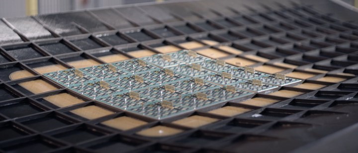
“Using this approach, however, we could make the AFP process for the orthogrid very efficient,” says Nijhuis. “So, after placing the outer skin, we placed the tapes for the stiffeners, and for half of these plies we cut in one direction and then for the other half of the plies, we cut in the perpendicular direction.” For example, if tapes in the first ply were placed continuously down the lengthwise stiffeners, those for the transverse stiffeners were placed, cut before each lengthwise stiffener and then placement resumed after each lengthwise stiffener. For the second ply, the transverse stiffeners received the continuous tapes while those for the lengthwise stiffeners were placed cutting before and resuming after each transverse stiffener. This pattern was then alternated until the full height of the stiffeners, slightly less than 10 millimeters, was completed.
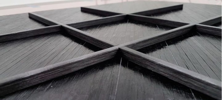
This close-up shows the alternating cuts made in the AFP layup at the stiffener crossings.
Developing a reusable vacuum bag
The next challenge was the need to support the stiffeners during vacuum bagging and autoclave cure. The number of metal tooling blocks needed, if they had been used, would have totaled 500 or more, says Nijhuis. This is because for each square created by the orthogrid, the tooling blocks would be trapped inside by the cured stiffeners. Thus, to enable disassembly for demolding, each of these blocks would typically comprise two halves. Also, because of the panel’s curvature, no two blocks would have the same thickness and shape, and for every production cycle, the blocks would have to be inserted before cure, and removed and cleaned after cure. Meanwhile, the conventional disposable vacuum bag used with such tools would be discarded after each cure cycle.
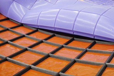
Production was also simplified by replacing hundreds of metal tooling blocks with a single re-usable silicone vacuum bag to support the stiffeners during cure.
“A key part of this program was to also make this part of the process more affordable,” notes Nijhuis. “So, we came up with the idea to support the orthogrid with a molded silicone vacuum bag that could be reused. Vacuum bagging for cure then becomes very easy — just a large, molded blanket that is easily applied across the layup and that’s it.”
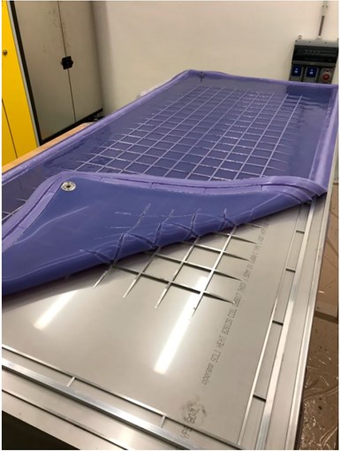
The bag was molded by spreading room-temperature cure silicone onto a machined aluminum pattern.
A small silicone bag comprising four stiffeners was trialed using EZ-brush VacBag Silicone (Smooth-On Inc., Macungie, Pa., U.S.) over a machined aluminum grid. Several test panels were made using this bag but the surface quality was less than desired because the surface tension of the silicone reduced resin flow. This was resolved by using a layer of Airtech Advanced Materials (Huntington Beach, Ca., U.S.) A4000 high-temperature, fluoropolymer release film on the silicone bag side. The tests also showed that conventional tacky tape, used to seal off the edge of the prepreg layup, did not stick to the silicone bag and silicone-based tapes were cured to the bag after an autoclave cycle. To address this, a groove was made at the edge of the final reusable bag to ensure a sufficient seal and vacuum tightness, eliminating the need for any tape.
Due to the limited pot life of EZ Brush silicone and the larger size of the final reusable bag, production was switched to Transil 20 (Mouldlife, Suffolk, U.K.), a two-component, platinum-based cure silicone that crosslinks at room temperature and can be used at temperatures up to 240°C. The bag was made at NLR by composite materials distributor MC Technics (Visé, Belgium). Parts A and B were mixed in an automatic mixing machine. Polyester knitted fabric reinforcing cloth and ADD PA Thixo rheology modifier from Silicone Composites, now acquired by Composite Integration (Saltash, U.K.), were used near the vacuum seal grooves. Using this final bag, the ACASIAS demonstration panel was cured in an autoclave at 180°C and a pressure of 7 bars for two hours.
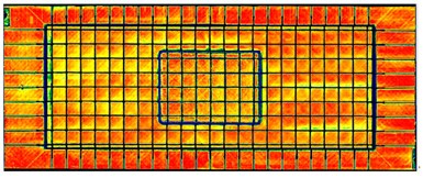
Ultrasonic testing results showed uniform quality in the completed demonstrator panel.
The cured demonstration panel was inspected visually and with ultrasonic testing. The panel was deemed to be of high quality, due in part to the more uniform distribution of pressure achieved with the flexible silicone bag versus metal tooling blocks. Hence, there were no areas with a lower pressure during cure to allow voids. C-scan images also confirmed panel consolidation to be uniform.
Complex isogrid manufacturing simplified
ACASIAS successfully demonstrated that a grid-stiffened composite fuselage panel can be made in a fully automated and efficient way with very low scrap rates. Curing of such panels was also shown to be made affordable and with a reduced environmental impact thanks to the reusable silicone vacuum bag.
“Of course, the issue of using silicone in a composites facility is serious due to the risk for contamination, which can degrade laminate strength and create non-bonding issues,” concedes Nijhuis. “But this can be addressed by curing the silicone bag in a separate production area, away from the layup. Also, if the layup is fully automated, then there is no risk of contamination from human touch, and if the silicone is fully cured and used only in the curing area, this helps as well.”
Has ACASIAS, then, finally succeeded in making isogrid manufacturing simple? “That’s why we came up with this approach and did the trial within this program,” says Nijhuis, “to see if we can make isogrids easier to produce across all the programs which we are running. And I think the whole world could be doing this more cheaply. That’s the main driver in all the composites manufacturing techniques at this moment — we should be cutting cost and time.”
He notes that development continues: “In the next programs, we are extending these processes to thermoplastic composites, making a similar kind of panel. This will be more challenging due to the much higher temperatures, and thus, a silicone bag is not possible. We will need to find a material which can be similarly formed and handled at those high temperatures. But we are working on that and have made the first panels. We are now proceeding towards larger panels. The challenge is to make this higher-temperature thermoplastic composites process robust, but the reward will be a further extension of the improved cost, manufacturing time and sustainability for very lightweight, high-performance structures that we’ve already demonstrated.”


.jpg;maxWidth=300;quality=90;format=webp)


Related Content

Drawing design cues from nature: Designing for biomimetic composites, Part 1
Biomimicry is an interdisciplinary methodology that can inform composites design and manufacturing via use of more effective and sustainable materials, structural fabrication and technological practices.
Read More
Protecting EV motors more efficiently
Motors for electric vehicles are expected to benefit from Trelleborg’s thermoplastic composite rotor sleeve design, which advances materials and processes to produce a lightweight, energy-efficient component.
Read More
Collins Aerospace demonstrates new thermoplastic composites capabilities
Collins Aerospace in Almere has produced a 7-meter raceway for the Clean Sky 2 MFFD lower fuselage using novel CCM and tooling technology while the Riverside facility in the U.S. advances AFP and welding as part of global strategy for more sustainable airframes.
Read More
Plant tour: ÉireComposites, Galway, Ireland
An in-house testing business and R&D focus has led to innovative materials use and projects in a range of markets, from civil aerospace to renewable energy to marine.
Read MoreRead Next

Composites end markets: Energy (2024)
Composites are used widely in oil/gas, wind and other renewable energy applications. Despite market challenges, growth potential and innovation for composites continue.
Read More
From the CW Archives: The tale of the thermoplastic cryotank
In 2006, guest columnist Bob Hartunian related the story of his efforts two decades prior, while at McDonnell Douglas, to develop a thermoplastic composite crytank for hydrogen storage. He learned a lot of lessons.
Read More
CW’s 2024 Top Shops survey offers new approach to benchmarking
Respondents that complete the survey by April 30, 2024, have the chance to be recognized as an honoree.
Read More