


BBG GmbH & Co. KG (Mindelheim, Germany) develops and produces molds and end-to-end manufacturing systems for plastics and composites processing. Founded in 1960 and renamed BBG in 2001, the company’s 200 employees are split across four facilities, including two in China and one in the U.S. (Oxford, Mich.). In composites, BBG progressed from equipment and molds for resin injection molding (RIM) and long fiber injection (LFI) using polyurethane to resin transfer molding (RTM) using epoxy resin and continuous glass and carbon fiber. Now, it has developed molds and injection equipment for high-pressure RTM (HP-RTM) of carbon fiber-reinforced polymer (CFRP) wrapped pressure vessels for storing hydrogen gas. “We started the development project with a German automotive OEM in 2015,” says Gerhard Hörtrich, senior sales/project manager for BBG GmbH & Co. KG. “We have now produced three molds and are developing the technology further.”
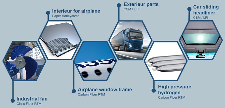
BBG GmbH & Co. KG has a long history in composites, manufacturing equipment and/or molds for industrial, automotive and aerospace applications using glass and carbon fiber in resin transfer molding (RTM), as well as glass fiber chopped strand mat (CSM) and long fiber injection (LFI). Photo Credit: BBG GmbH & Co. KG
Why hydrogen tanks?
“We see more and more development going to hydrogen, especially in Europe,” Hörtrich explains (see hydrogen strategies announced by Tier 1 suppliers Plastic Omnium and Faurecia and 's hydrogen content collectionCW). “Governments want to produce hydrogen using renewable energy from wind turbines, which achieves a green footprint. Hydrogen-powered cars provide the same driving range as gasoline and it only takes five minutes to fill the tank, which is much shorter than recharging batteries. We see that production of hydrogen cars will definitely grow in the next years.” (link to CW hydrogen content collection?)


Hörtrich adds that BBG GmbH & Co. KG is a strong partner for OEMs and Tier suppliers that want to develop new technologies. “We want to be at the forefront of the hydrogen industry, helping to develop the technology that is needed,” he says. For cars powered with hydrogen fuel cells, this means tanks to hold hydrogen gas at high pressures (typically 350 and 700 bar) that are smaller and easier to accommodate within the vehicle and also cheaper to produce. Typically, hydrogen tanks are type IV pressure vessels comprising a plastic liner overwrapped with carbon fiber-reinforced epoxy using wet filament winding.
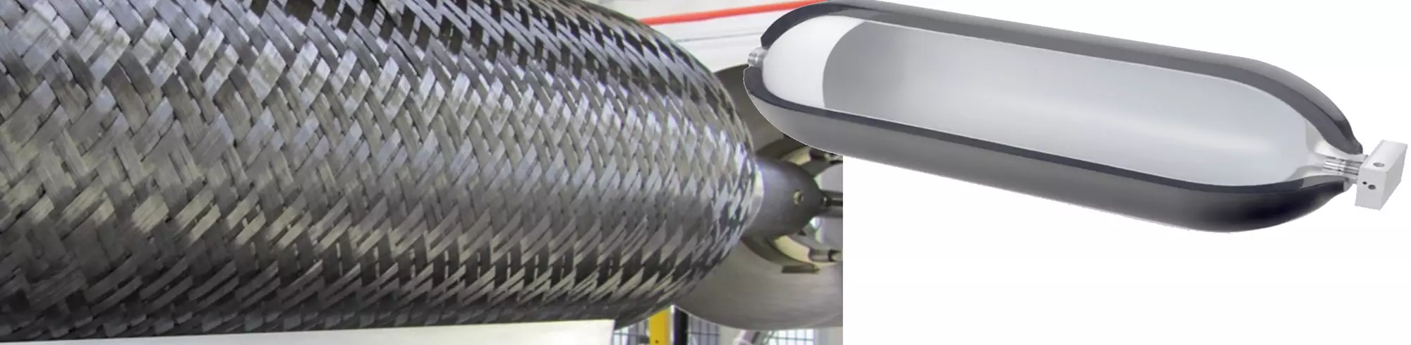
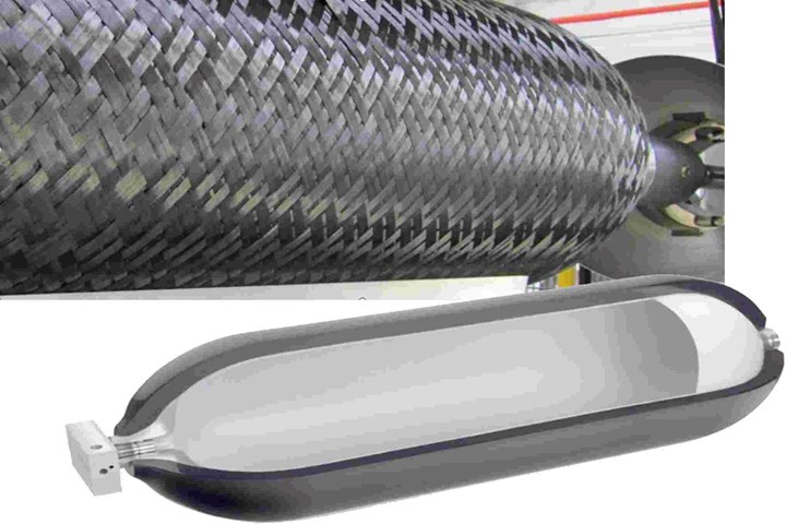
BBG GmbH & Co. KG and its automotive partner, however, sought to meet the needs for smaller, less expensive tanks by using HP-RTM, injecting liquid epoxy resin into a dry carbon fiber braid pulled over the plastic liner. The three different molds developed are explained below.
Tool #1


Tool #1
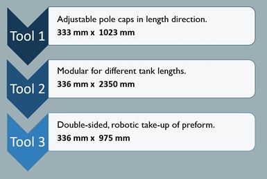
333-millimeters x 1023-millimeters (1-foot x 3-foot). Photo Credit: BBG GmbH & Co. KG.
This 333-millimeter x 1023-millimeter (1-foot x 3-foot) tool featured adjustable pole caps to compensate for length tolerances of the preform, aiming to eliminate dry spots or uneven resin distribution. Other features included hydraulic ejector pins in the lower mold for demolding and the development of a sealing concept suitable for series production at an injection pressure of up to 40 bar. Voids and resin pooling were controlled by special venting modules, and resin infiltration of the dry preform was monitored using pressure sensors and resin flow detection sensors.
The sequence for tank manufacture was as follows: place preform in the mold, evacuate air, close mold and inject resin. “Due to the high pressure inside of 40 bar (normal RTM would be 5-8 bar),” Hörtrich explains, “we needed a high pressure in the press of 400 tons to close and seal the mold to prevent resin escape. The sealing section was very important and challenging to achieve with the movable tool cap. You also have to make sure that the injection pressure does not destroy the preform as the resin is injected.”
Resin was injected at two inlet ports. “We used additional sealing along the injection channels around the mold cavity,” says Hörtrich. “It was a long development to find the right seal profile.” The tank made with this tool has a filling pressure of 800 bar and an operational pressure of 700 bar. It was tested to a burst pressure of 1,600 bar. “The CFRP is what holds it all together,” notes Hörtrich.
Tool #2
This 336-millimeter x 2350-millimeter (7-8 feet in length) modular tool was designed to produce different tank lengths. “The goal was to have an adjustable length from 1 to 2.35 meters,” says Hörtrich. “The middle tool section is adjustable. We also integrated new robotics for automated positioning of the preform and fast closing of the mold. We also enabled fast heating of the preform, controlling the tool temperature up to 140°C (± 3°C). Normally, the tolerance would be ± 5°C, so this also required some development. The downside was that it required a lot of power for the fast heating, so not very efficient, but it worked.”


Tool #2
336-millimeters x 2350-millimeters (7-8 feet in length). Photo Credit: BBG GmbH & Co. KG.
For this tool, the injection port was on the side, extending over the whole length of the cylinder. “This is a different approach to avoid bubbles in the resin,” says Hörtrich. “We are injecting resin that has been degassed. We fill the mold to 95% and then apply vacuum. But until the mold is filled to 95%, you need venting so the air can go out.”
He notes that sealing of the venting system was hydraulic not pneumatic. “This was due to the required force versus the 40-bar inner cavity pressure as the mold was filled with resin,” Hörtrich explains. “Pneumatic cylinders are designed for a pressure of 6 to 10 bar, while hydraulic systems are commonly designed for 250 bar.” However, a separate pneumatic system was also required. “It is crucial to make sure that the plastic liner doesn’t collapse while the resin is injected,” notes Hörtrich. “To prevent this, we filled the plastic liner with compressed air, which required a separate, specially-designed air compressor for maintaining over 40 bar of air pressure.”
This tool was completed with BMW (Munich, Germany), who started with their first hydrogen tank in 1990. “BMW continues to seek a serial production solution for hydrogen storage tanks in cars,” notes Hörtrich.
Toll #3
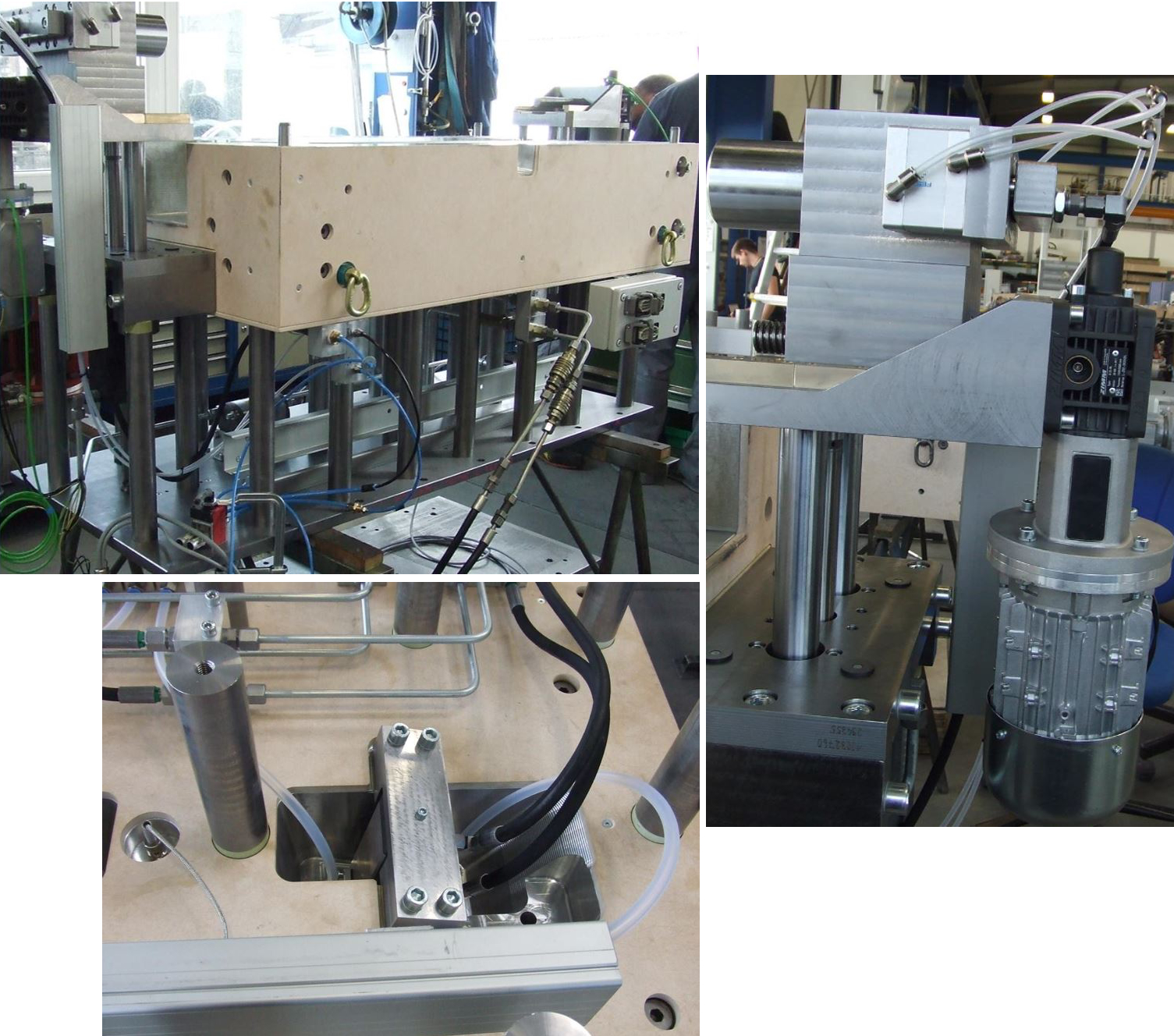
Tool #3
336 millimeters x 975 millimeters with electromechanical system for positioning the preform (right) and hydraulic venting module with integrated vacuum connection (bottom). Photo Credit: BBG GmbH & Co. KG.
This tool was 336 millimeters x 975 millimeters and highly automated.Process steps that were adjusted or actuated manually on Tool1 and Tool2 were now made fully automatic and were controlled using simple process settings (SPS) as a part of the tool or of the double-sided robot-arm that we used,” says Hörtrich. These process steps included:
- Picking up the preform;
- Placing and positioning the preform in the mold;
- Length adjustment of the pole cap;
- Ejecting the molded part;
- Picking up the finished part and moving it out of the tool.
An electric motor-driven system was used to position the preform at both left and right pole caps, where metal inserts were also placed to form the tank bosses. “These were stainless steel inserts to prevent galvanic corrosion with the carbon fiber preform and were held in position via tie rods coming from the outside of the tool,” explains Hörtrich. They were encapsulated with resin during injection and integrated into the tank composite during cure.
This project was funded by German government as “HyPress Matrix” to achieve fiber injection of a CFRP tank, notes Hörtrich. “For this tool, we used two injection gates [or inlets] located at the pole caps, enabling the entire mold to be filled from one end to the other. The original goal was 20 minutes for the cycle: place preform, close mold, injection, cure and demold tank. We reached 25 minutes for one tank.” He concedes this cycle time requires, in fact, multiple molds but only 1 tank per car.
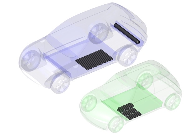
Space-saving installation of small hydrogen storage tanks in the floor of zero-emission vehicles. Photo Credit: BBG GmbH & Co. KG.
“Development is now shifting towards multiple small tanks instead of one big tank,” says Hörtrich, but stresses this is not driven by cycle time. “The reason is the available space in the car, and the ability to maximize this by implementing multiple small tanks. The battery packs for electric vehicles are composed of many smaller batteries. The idea for the smaller hydrogen tanks is the same. However, by reducing the tank size, we are also able to increase the number of cavities per tool, and thus significantly reduce the cycle time per tank.”
Future tank development
“We started in composites with glass fiber and polyurethane encapsulation for automotive windows,” says Hörtrich, “but we wanted to continue advancing and diversifying. Now, we want to contribute to the development of tools for composites production and have started with CFRP tanks. For the future, we will refine RTM tools for tanks adjustable up to 100 millimeters in length. Automotive OEMs need space-saving installation — a 2-meter-long and 0.35-meter-diameter tank is too big.” The next step, he says, is a tool with diameter less than 100 millimeters and length from 1-3 feet, not longer. “This saves space and allows you to put the tanks in the car floor, so that less space is lost to tank storage,” Hörtrich explains.
But isn’t manufacturing and using more tanks per car more costly? “Not if we can include 10-15 cavities per mold, so we are producing 10-15 tanks with a single injection,” says Hörtrich, “and you are buying a single system, not multiple systems. The goal, ultimately, is to reduce tank space and cost.


Related Content

Materials & Processes: Fibers for composites
The structural properties of composite materials are derived primarily from the fiber reinforcement. Fiber types, their manufacture, their uses and the end-market applications in which they find most use are described.
Read More
Composites opportunities in eVTOLs
As eVTOL OEMs seek to advance program certification, production scale-up and lightweighting, AAM’s penetration into the composites market is moving on an upward trajectory.
Read More
Forvia brand Faurecia exhibits XL CGH2 tank, cryogenic LH2 storage solution for heavy-duty trucks
Part of its full hydrogen solutions portfolio at IAA Transportation 2022, Faurecia also highlighted sustainable thermoplastic tanks and smart tanks for better safety via structural integrity monitoring.
Read More
Materials & Processes: Resin matrices for composites
The matrix binds the fiber reinforcement, gives the composite component its shape and determines its surface quality. A composite matrix may be a polymer, ceramic, metal or carbon. Here’s a guide to selection.
Read MoreRead Next

BBG ventures into new markets with innovative composite press
Based on composite spray molding, the new press will be used to manufacture interior parts for railway cars for Chinese railway supplier.
Read More
BBG presents self-closing HP-RTM molds for CFRP compact hydrogen tank production
The autonomous concept, sufficient for series production, enables lower investment costs. Up to 15 cylinders can be produced simultaneously per operation.
Read More
Carbon fiber in pressure vessels for hydrogen
The emerging H2 economy drives tank development for aircraft, ships and gas transport.
Read More