
Plant Tour: Fokker Aerostructures: Hoogeveen, Netherlands
This Dutch aerospace supplier leverages its founder’s pioneering spirit from a century ago to lead the way, today, in thermoplastic aerocomposites.


The Fokker name enjoys a long and storied history in aviation. It harkens back to the earliest days of manned flight, when Dutchman Anthony Fokker first flew his Spider aircraft over the city of Haarlem, in 1911. After founding a Dutch aviation company, Fokker set up Fokker Aviatik GmbH in Germany in 1912 to supply the German army.
Throughout the 1920s and 1930s, Fokker was, arguably, the best-known and most successful aircraft manufacturer in the world. In full flight in the aerospace industry by the 1950s, his company launched, in 1958, the F-27, a two-engine, single-aisle passenger plane that became the company’s signature aircraft. But by 1996, market forces had overcome Fokker Aviatik. The aircraft builder declared bankruptcy and ultimately ceased operations.


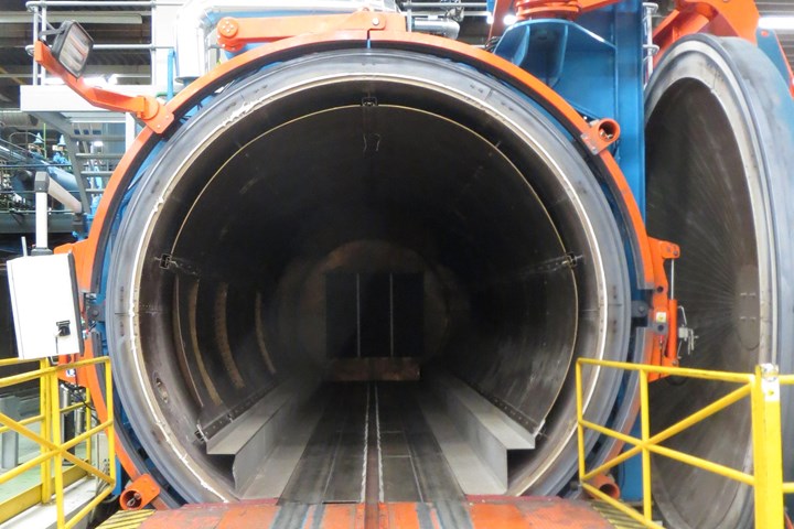
Fig 1: Although Fokker is famous for its thermoplastics expertise, the company still relies on the autoclave to consolidate many parts as they cool after forming because it remains the best tool for meeting porosity specifications. Source (all photos) CW/Photos: Jeff Sloan & Sara Black
But the Fokker name did not die. It lives on in business units spun off before bankruptcy. Three — Landing Gear, Electrical Systems, Services — make parts and perform maintenance and repair work, and carry on under the name Fokker Technologies. The fourth and most notable is Fokker Aerostructures. Headquartered in Papendrecht, The Netherlands, this developer and fabricator of thermoplastic composite structures for aerospace applications — the subject of this CW Plant Tour — is adding a significant chapter to the history of its storied name.
Turning the page: Thermoplastics
Fokker Aerostructures BV started its thermoplastics activity 25 years ago by creating a small R&D team that cooperated closely with material supplier TenCate Advanced Composites BV (Nijverdal, the Netherlands) and with prospective customers. Initial customers were the owner, Fokker Aircraft company, Dornier (Friedrichshafen, Germany) and Airbus (Toulouse, France). Thus, an ever-growing range of products was developed and taken into production. This ranged from initial applications, such as brackets, ribs, wing panels and floor panels, to fully assembled structures, including wing leading edges, rudders and elevators. A key player on the team proved to be gifted R&D engineer John Teunissen, who created and developed several new manufacturing technologies and product concepts. In 1995, a breakthrough was the development of Gulfstream 5 floor boards, which included primary structure pressure bulkheads. This led to a move towards fabrication of thermoplastic composite primary structure, with corresponding engineering and manufacturing knowledge.
Our hosts during our plant tour are Richard Cobben, VP technology, and Arnt Offringa, director, R&D. Well-known in the composites community for his thermoplastic composite expertise, Offringa guides us on the tour of Fokker’s large facility in Hoogeveen. Before the tour, Cobben presents the different Fokker companies. Then, in advance of leading us to the production floor, Offringa reviews some of the parts and structures that Fokker manufactures at the plant, most notably the rudder/elevator for the Gulfstream G650 business jet (read more in “Reinforced thermoplastics: Primary structure?” under "Editor's Picks" at top right), elevators and floorboards for the Gulfstream 5 business jet, rudder and elevators for the Dassault Falcon 5X, the wing leading edge for the Airbus A380 superjumbo passenger plane, and all of the access doors for all of the variants of the F-35 Lightning II fighter jet. With the exception of the F-35, each of these applications relies on thermoplastics and it’s thermoplastic composites on which the Fokker name now stands.
A strong proponent of thermoplastics, Offringa believes they will see only increased use and application in the aerospace market. The material, he notes, offers a toughness — as opposed to brittleness — that thermosets can’t match, making them suitable for use in structural and semi-structural applications.
“New designs can, therefore, be lighter in weight because the amount of composite plies can be reduced,” he contends. “Welded thermoplastic rudders and elevators are 10% lighter than their thermoset composite predecessors because of the so-called ‘post-buckled’ design” (discussed below). That said, thermoplastic composites fabrication at Fokker is not, as some thermoplastics proponents claim, an out-of-autoclave process. Indeed, the company still relies heavily on the autoclave to ensure that its products meet porosity goals (see Fig. 1, at left). “I know we like to think of thermoplastics as not needing autoclave cure, but for large parts, we see it as the best way to achieve the compaction and consolidation pressure required, to drive out any volatiles,” Offringa notes. “And for an aerospace structure, that is critical.”
Good buckling, R&D
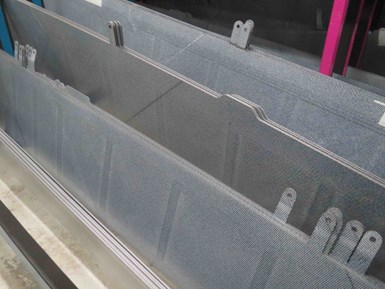
Fig 2: Themoplastics enable innovative rudder/elevator combo — these thermoplastic spars are for the Gulfstream G650 rudder/elevator and feature a design that, because of the material’s high toughness, allows for in-flight buckling, without damage or failure.
One of the first parts we see on entering the Hoogeveen facility are the just-molded spars for the Gulfstream G650 rudder/elevator (Fig. 2). They’re fabricated in lengths of 4m and 6m at thicknesses of just less than 1 mm to several millimeters. They’re consolidated in an autoclave and feature integrated ribs with regional thicknesses (from weldments). The material is TenCate Cetex carbon fiber/PPS.
These parts, says Offringa, are exemplary of the tough/not brittle attributes that make thermoplastics so appealing to aerospace fabricators and OEMs. They are designed, says Offringa, to buckle slightly during service, without breaking or cracking. “A thermoplastic rudder consists of thin skins welded onto a stiff internal skeleton of ribs and spars. When the rudder is used, it is loaded in torsion and the skins are allowed to buckle at 70% of limit load (the load that occurs once in the lifetime of an aircraft). This allows for thinner skins than otherwise, resulting in a weight reduction as compared to conventional composites.” Fokker’s thermoplastic composite parts are tested and certified at 1.5 times limit load.
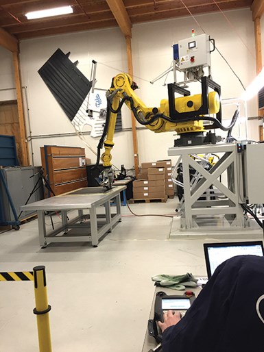
Fig 3: In-house equipment development: Much of the thermoplastic composites innovation that comes out of Fokker is a product of the company’s research and development lab, which features this automated fiber placement (AFP) machine, equipped with a Fokker-developed end-effector.
Much of what Fokker has learned about thermoplastic composites fabrication, assembly and performance is fueled by the company’s significant research and development (R&D) work, which is guided by Offringa. Fokker’s R&D lab employs 10 people and has equipment for environmental simulation, 3-D printing (provided by Leap Frog, Alphen aan den Rijn, The Netherlands), autoclave curing (from Italmatic Presse e Stampi Srl, Cassina de Pecchi, Italy) and automated fiber placement (AFP, see Fig. 3). The latter features a Fanuc (Minamitsuru-gun, Japan) robot, a Fokker-developed end-effector that features 35,000-Hz ultrasonic heating capability, and CGTech (Irvine, CA, US) control software.
It’s here in the R&D lab that Fokker has worked with Airbus and other partners on the Europe-based Thermoplastic Affordable Primary Aircraft Structure (TAPAS I and TAPAS II) projects (see “TAPAS 2: Next steps in thermoplastic aerostructures” under "Editor's Picks" at top right) to evaluate the performance of thermoplastic composites in aerostructures. Fokker also is involved with the European Clean Sky Joint Technology Initiative, part of which is comparing autoclave energy use between thermoset and thermoplastic materials. At the time of CW’s visit, a large fuselage panel demonstrator was being readied for display at a composites trade show.
Big assembly for the A380
Fabrication, however, is only half of the Fokker Aerostructures story, for the company invests just as heavily in assembly, which, when it came to thermoplastics, opened the door to welding methods. And it’s in development of thermoplastic welding technologies that Fokker has truly excelled. Fokker’s contract to manufacture the wing leading edges on the massive Airbus A380 from thermoplastic composites was one of the composites industry’s biggest news stories in the first decade of the 21st Century. That program also consumes the biggest space at the Hoogeveen plant. The work is done in the plant’s Tool Jig Room, so named because it is dominated by eight two-sided jigs — one side for the left wing, the other side for the right wing — in which Fokker welds the thermoplastic leading edge skin and spar with a series of reinforcing ribs. Each jig accommodates a 3.5m length of leading-edge skin. Each wing leading edge comprises eight 3.5m sections, for a total leading-edge length of 26m, spanning from each wing’s inboard engine to its wingtip.
The welding of the thermoplastic skins and thermoplastic ribs is important because this assembly technology creates what is, in effect, a unified thermoplastic composite structure. The benefit is significant because it relieves the manufacturer of what would otherwise be a costly additional step necessary for aircraft certification: Adhesively bonded skins and ribs would require the redundant use of mechanical fasteners. But welded skins and ribs do not. However, this makes the consistency and repeatability of the welding process critical.
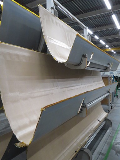
Fig. 4: Wing leading edges awaiting welding — molded of glass fiber/PPS, the Airbus A380 wing leading-edge skins on these racks soon will be integrated with ribs and spars via welding in Fokker’s large Tool Jig Room.
The leading edge skin (Fig. 4) and spar are fabricated via hand layup, using a glass fiber/PPS semipreg provided by TenCate Advanced Composites under the Cetex brand. The skin and spar are layed up using single plies of the semipreg, which are cut on Gerber Technology (Tolland, CT, US) flatbed cutting tables. Ply positioning guidance is provided by Virtek Vision International Inc. (Waterloo, ON, Canada) laser projection systems. The parts are bagged and then consolidated in an autoclave at 320°C, with a total cycle time of 3 hours — 6-9 hours is typical for thermoset composites.
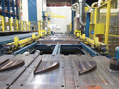
Fig. 5: Compression molding of rib components — A380 wing leading-edge ribs are compression molded, using materials cut from TenCate’s Cetex preconsolidated glass fiber/PPS sheets, on this massive press supplied by automated machinery manufacturer Pinette Emidecau (Chalon Sur Saone, France).
Ribs and stiffeners (Fig. 5) are compression molded on a Pinette Emidecau Industries (Chalon Sur Saone, France) press using the same Cetex material, but supplied by TenCate as preconsolidated sheets. The Cetex sheets are first softened in an infrared heater and then quickly transferred to the press, which offers a 0.5-second closed cycle, says Offringa. Stiffeners for the wing leading edge, fabricated from glass/PPS, are robotically machined and drilled near the Pinette press by a Panasonic VR-016 robotic system.
All of the wing leading edge parts — skin, spar, ribs, reinforcements — eventually come together in the Tool Jig Room for assembly and welding. Fokker has experimented over the years with a variety of welding technologies, but for A380 wing leading edge assembly, it settled on resistance welding. For that method, a metal mesh strip coated with PPS is attached to the contact edge of each rib (Fig. 6).
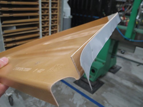
Fig 6: “Meshing” leading edges ribs and skins — molded ribs for the A380 wing leading edge are bonded to the skins by means of resistance welding, in which a metal mesh strip coated with PPS is attached to the edge of the rib. A current is applied to the mesh, which softens the PPS and bonds the rib to the skin. The metal mesh becomes part of the bond.
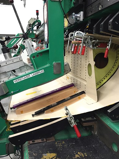
Fig. 7: Section-by-section assembly — an A380 wing leading edge skin and its ribs, spar and stiffeners, mounted in an assembly jig, is shown here during resistance welding. Each jig holds one 3.5m section of wingskin. Each wing leading edge comprises eight 3.5m sections, for a total length of 26m.
The rib is then inserted into the jig, secured by a rib holder rail. The welder then moves from rib to rib, and a current is applied to each for 1 minute at one end of the metal mesh. This is followed by a 1-minute hold and a 1-minute cool-down. The current melts the PPS around the mesh and creates a bond with the skin. The mesh remains in place and becomes a permanent part of the weldment. After all ribs are bonded, the spar is attached and held in place with stiffeners, which also are welded (Fig. 7).
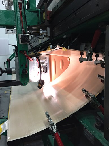
Fig. 8: Robotically automated welding — all welding of the A380 wing leading edge is done with robotic equipment, which measures the distance traveled along the skin to recognize which rib it’s welding.
Much of this assembly, says Offringa, is automated, but some manual labor is required to attach holding fixtures. The welding itself, however, relies on automation for both speed and consistency. “An electronic ruler on each jig tells the machine which rib it’s on,” says Offringa (Fig. 8).
Advancements in induction welding
Although the resistance welding regimen employed on the A380 wing leading edge assembly is an effective and now relatively mature Fokker technology, the assembly of parts for the Gulfstream 6 and Dassault Falcon 5X via induction welding represents the very latest developmental step that is already delivering on its very great promise. This work is done at the next stop on CW’s tour, the Marconi Street Building, a short drive from Fokker’s main facility in Hoogeveen. Here, we see a jig design and automated process that has evolved beyond that used for the A380 wing leading edge configuration.
The advantage of induction over resistance welding, says Offringa, is that it does not require use of a metal strip or other conductor, thus there is no weight penalty for the weldment. Fokker’s induction method was developed and provided by KVE Composites Group (The Hague, The Netherlands). Dubbed Induct, it generates eddy currents in the electrically conductive carbon fiber reinforcement within the thermoplastic laminate. The currents are generated by moving an induction coil over the weld line; the eddy currents it generates then heat the laminate from the inside. The parts that are being welded must be positioned, says KVE, in a proprietary tooling material (steel, with a “special” ingredient) that is transparent to the electromagnetic field and has good thermal conductivity. The coil motion at Fokker is actuated robotically.
Offringa first shows CW the assembly jig for the Gulfstream 6 rudder, which consists of two spars with supporting ribs. All are fabricated from carbon fiber/PPS via compression molding. As with the A380 wing leading edge assembly, the Gulfstream 6 rudder jigs (there are six, total) are oriented horizontally and elevated about waist high. A jig is 4 to 6m long and features horizontal slots to hold the spars and vertical slots to position the ribs against the spars. With all parts in place, a robot equipped with a KVE induction coil moves into various slots along the jig, welding each rib to the spars.
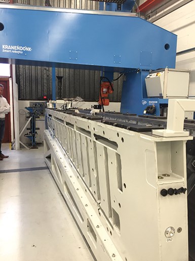
Fig. 9: At Fokker, welding’s future is seen as “lights out” technology. For the Dassault Falcon 5X elevator, Fokker employs next-generation induction welding technology that, unlike resistance welding, allows direct thermoplastic-to-thermoplastic bonding and obviates the need for a metal mesh strip. This assembly jig holds all of the spars and ribs for the elevator; during the night shift, robotically guided induction coils are inserted into the jig to bond the parts together.
For the Dassault Falcon 5X elevator, Fokker has three jigs, similar to the Gulfstream jig system but improved in the sense that the six jigs are now replaced by only three, using the same induction technology (see Fig. 9). On these jigs, day shift labor is used to load composite parts into the jig, and then a robot works overnight to induction weld the resulting assembly, a process that takes about six hours.
A new chapter
Offringa sums up his company’s wholehearted focus on thermoplastics, and the philosophy Fokker refers to as “aircrafting”: “When we began our work with thermoplastics, the supposed advantages had yet to prove themselves. After a certain time they become clear, and then new, unpredictable advantages revealed themselves, such as the benefits of post-buckling design, fewer production steps and greater design freedom, compared to thermosets.” The material and design innovations represent aircrafting, which reflects the Fokker commitment to and appreciation for all the details that go into designing, assembling and then maintaining a modern aircraft.
Now, yet another chapter in the company’s century of experience is beginning. Fokker Technologies announced on July 28 that it will be acquired by GKN plc (Isle of Wight, UK). Hans Büthker, Fokker Technologies’ CEO, has said that Fokker can benefit greatly from the scale, innovation and financial power of GKN, and the combined entity will lead to new opportunities for Fokker employees who will be participating in some of the world’s largest and most challenging aerospace projects.
“A strong focus on a limited number of unique technologies,” Offringa says, in conclusion, “has proven a successful way to create new business opportunities.”


.jpg;maxWidth=300;quality=90;format=webp)


Related Content

Manufacturing the MFFD thermoplastic composite fuselage
Demonstrator’s upper, lower shells and assembly prove materials and new processes for lighter, cheaper and more sustainable high-rate future aircraft.
Read More
Plant tour: Joby Aviation, Marina, Calif., U.S.
As the advanced air mobility market begins to take shape, market leader Joby Aviation works to industrialize composites manufacturing for its first-generation, composites-intensive, all-electric air taxi.
Read More
Plant tour: Albany Engineered Composites, Rochester, N.H., U.S.
Efficient, high-quality, well-controlled composites manufacturing at volume is the mantra for this 3D weaving specialist.
Read More
The potential for thermoplastic composite nacelles
Collins Aerospace draws on global team, decades of experience to demonstrate large, curved AFP and welded structures for the next generation of aircraft.
Read MoreRead Next

Thermoplastic composites save weight in rotorcraft aerostructure
This helicopter structure outdoes both metal and thermoset-composite alternatives.
Read More
Thermoplastic composites: Primary structure?
Yes, advanced forms are in development, but has the technology progressed enough to make the business case?
Read More
Reinforced thermoplastics in aircraft primary structure
Carbon/PEKK floor beams prove production worthiness of lower cost, fast coconsolidation process.
Read More