


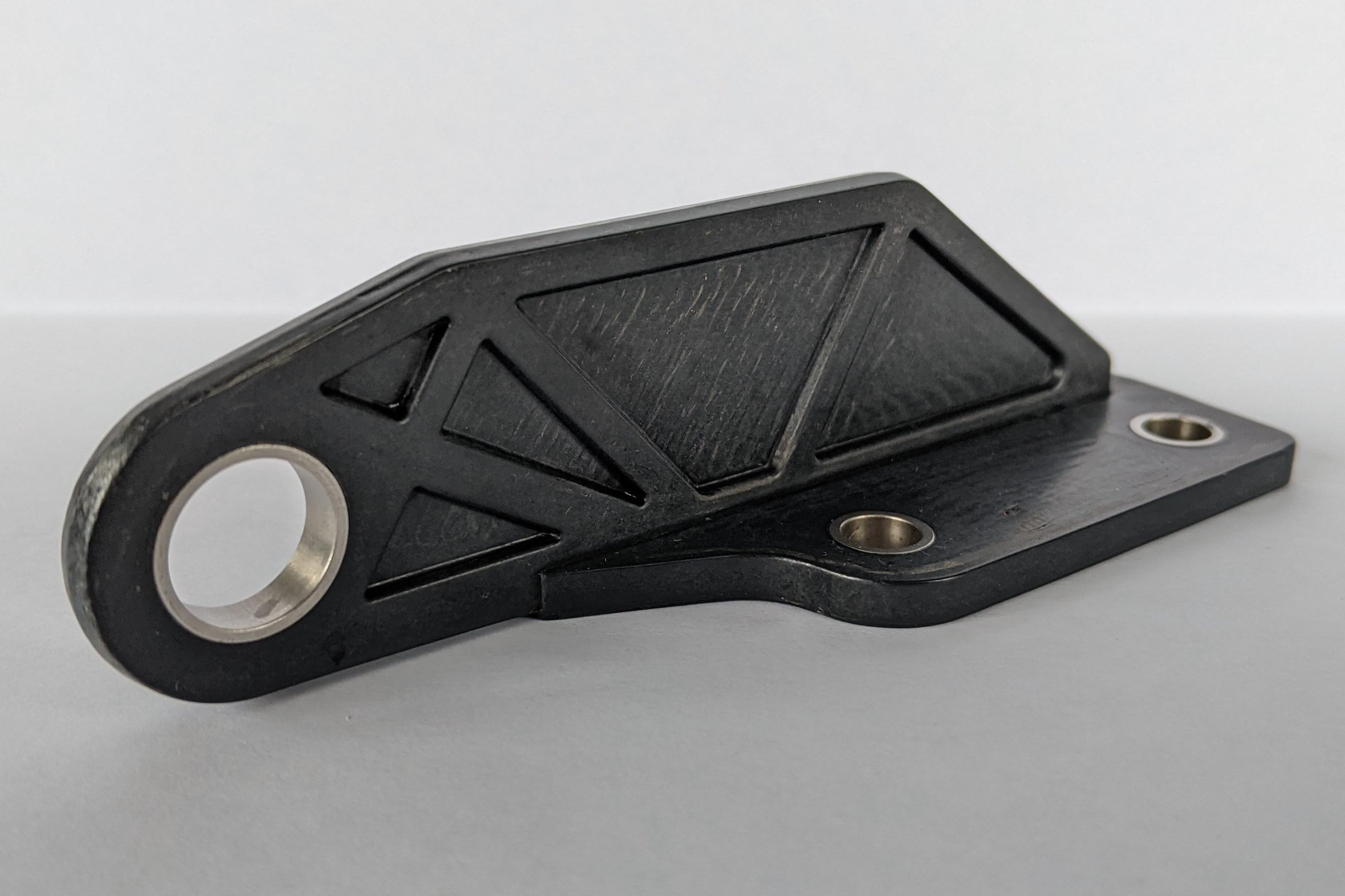
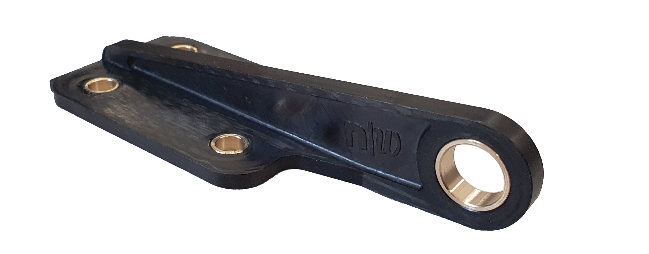
Figure 1. CFRTP hinge. FHNW in Switzerland collaborated to optimize this carbon fiber/PEKK bracket made using 9T Lab’s Additive Fusion Technology. Photo Credit, this image and image above title: 9T Labs
9T Labs (Zürich, Switzerland) has developed a 3-step manufacturing workflow called Additive Fusion Technology (AFT) to produce composite parts using a cost-competitive and automated process. This workflow begins with designing and analyzing a part using 9T Labs’ Fibrify design software. Continuous fiber-reinforced preforms are then created by deposition of a unidirectional tape filament in 9T Labs’ Build Module. These preforms are then placed in 9T Labs’ Fusion Module and compression molded. This final consolidation step merges the preforms, eliminates voids and outputs lightweight, high-strength net-shape parts.
This integrated process chain enables serial production of parts having >60% fiber-volume fractions and <1-2% voids with minimal waste and at lower cost than metals. Depending on part size, a single Build Module and Fusion Module set — both have a build envelope of 350 × 270 × 250 millimeters — can produce up to 5,000 preforms and 10,000 parts per year, respectively. AFT also enables complex, fine-scale details and very accurate control of fiber orientation to tailor designs for optimized load-carrying capability, weight, manufacturing speed and cost.


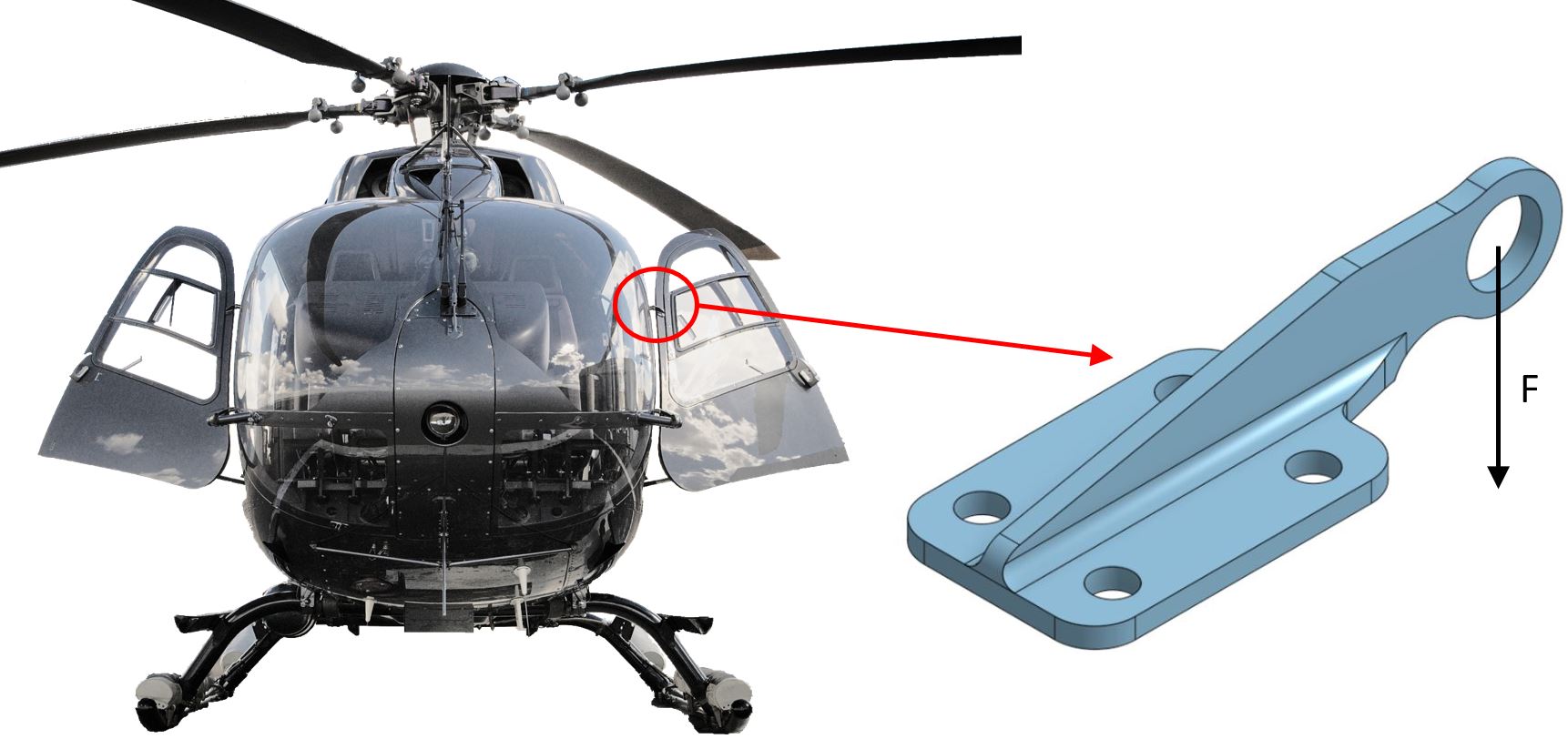
Figure 2. Metallic benchmark. The benchmark in this study was an aerospace-grade, CNC-milled stainless steel part measuring 112 × 42 × 22.5 millimeters with a maximum static load of 2.172 kilonewtons perpendicular to the bearing force with the door open. Photo Credit: Wikimedia Commons, photographer Abrileroux (left) and 9T Labs (right).
9T Labs collaborated with the University of Applied Sciences Northwestern Switzerland (FHNW, Windisch) to study the use of AFT to produce a structural carbon fiber-reinforced thermoplastic (CFRTP) hinge for a helicopter door (Fig. 1). The benchmark was a CNC-machined stainless steel hinge used on an Airbus Helicopters (formerly Eurocopter) EC135 door. This hinge was attached to the rotorcraft’s carbon fiber/epoxy door with four M8-sized bolts and designed to withstand a maximum static load of almost 2.2 kilonewtons of force perpendicular to the bearing load with the door open (Fig. 2).
Previously, a team in France had benchmarked the same part using hand-laminated and compression-molded chopped carbon fiber (CF)/polyetheretherketone (PEEK) tapes. The goal of the 9T Labs/FHNW study was to outperform the benchmark, which had a yield point of 3 kilonewtons, as well as the French design, which failed at 4.2 kilonewtons.
Iterating AFT designs, increased failure load
Three AFT designs were developed and printed using readily available CF/polyetherketoneketone (PEKK) tapes — pre-slit to the equivalent of 1-2K tows — and neat polymer filaments. All three 3D-fabricated designs incorporated metal bushings in the four bolt holes and in the main bearing hole for the hinge pin. The process began by using the 9T Labs’ cloud-based Fibrify software suite, which interfaces with common structural analysis packages via plugins.
The Fibrify design suite is an extension to the SpaceClaim 3D modeling tool within the Ansys (Canonsburg, Pa., U.S.) CAE/multiphysics simulation environment. For the helicopter door hinge, the first black metal design (Fig. 3a) was imported from an existing CAD file into SpaceClaim. This design used the same internal and external geometry as the benchmark. Fiber paths were laid out using Fibrify options (e.g., band generator, line or contour reference for infill, vertical distribution tool, etc.) to provide a typical quasi-isotropic (0°, 90°, ±45°) laminate with no optimization to exploit anisotropic composite properties — for example, there was no fiber orientation per specific geometries or load paths. The black metal part comprised 34 layers in the bottom horizontal plate and 26 layers in the vertical plate with each layer measuring 0.2 millimeter thick.
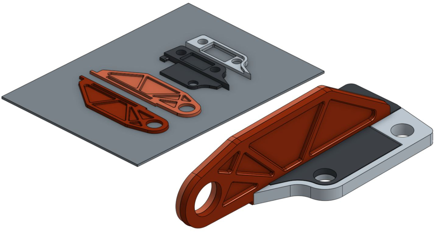
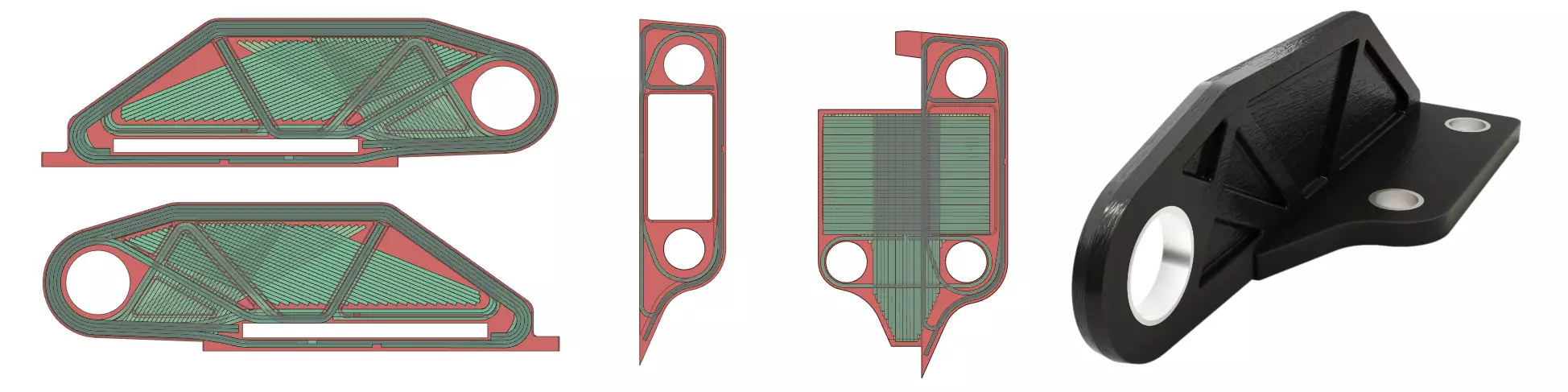
(d) Use of multiple printed subparts enabled optimized fiber placement in all directions.
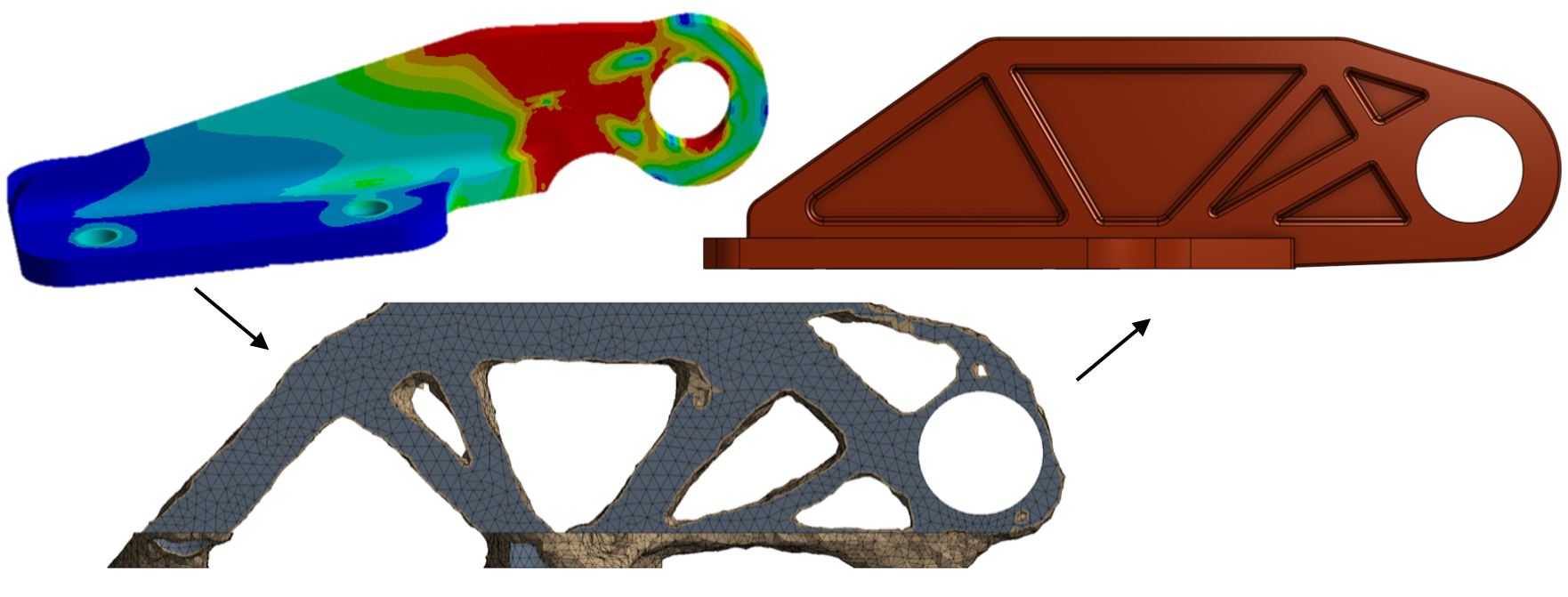
Figure 3. Steps to an optimized structure. 9T Labs first developed a non-optimized black metal design (a). Topology optimization (b) resulted in a first fiber layup (c) which was then improved in a second fiber layup (c) by adding local reinforcement at the vertical and horizontal plate junction. The final optimization (d) split the hinge into four printed subparts subsequently fused in the 9T Labs Fusion Module.
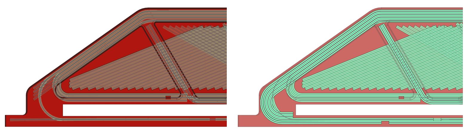
Dimensions for the next two designs — first fiber layup and second fiber layup (Fig. 3c) — were modified slightly (see table in Fig. 4) to speed up printing; fiber orientations also were optimized to take full advantage of anisotropic composite properties.
First fiber layup. Optimization began by exporting the black metal design into Ansys to run finite element analysis (FEA) simulations. The design was exported as an HDF5C file into Ansys Composite PrepPost (ACP) for isotropic optimization. The hinge boundary conditions and loads were entered and simulation results were used to improve the CF/PEKK hinge design (Fig. 3b).
This resulting first fiber layup (Fig. 3c) improved failure load by 200% compared to the black metal design in FEA simulations. Failure occurred away from the hinge pin toward the “back” of the part where the vertical plate meets the horizontal plate.
Second fiber layup. To further increase the strength of the part, a second optimization was then performed, adding fiber to reinforce the initial failure area. This second fiber layup increased failure load by another 45% and shifted failure to the hinge pin area in the vertical plate. Thus, the failure was now in the area of a design-restricted geometry, so that no further optimization was possible without changing geometry and/or thickness of the part beyond what was allowed in this project.
Validated results
The first and second fiber layup designs were produced using a multi-body strategy, splitting the part into four subparts (Fig. 3d). This approach allows fibers in all spatial directions to fully exploit the anisotropic features of continuous fiber printing, aligning the fibers to the loads. The four subparts were printed using 9T Labs’ Red Series Build Module and then fused together by compression molding in the 9T Labs’ Fusion Module using a machined steel matched tool set. Note that only 6 kilowatt-hours of power were used for compression molding at 350°C with 45 kilonewtons of press force for a cycle time of 20 minutes. This power consumption could be further reduced by further optimizing process parameters.
The printed and compression-molded AFT hinges were then mechanically tested by FHNW. The bottom horizontal plate of the hinge was bolted to a fixed metal plate in a load cell and vertical force was then applied to a hinge pin installed in the main bearing hole of the vertical plate. Each hinge was tested to failure.
Optimized part comparison
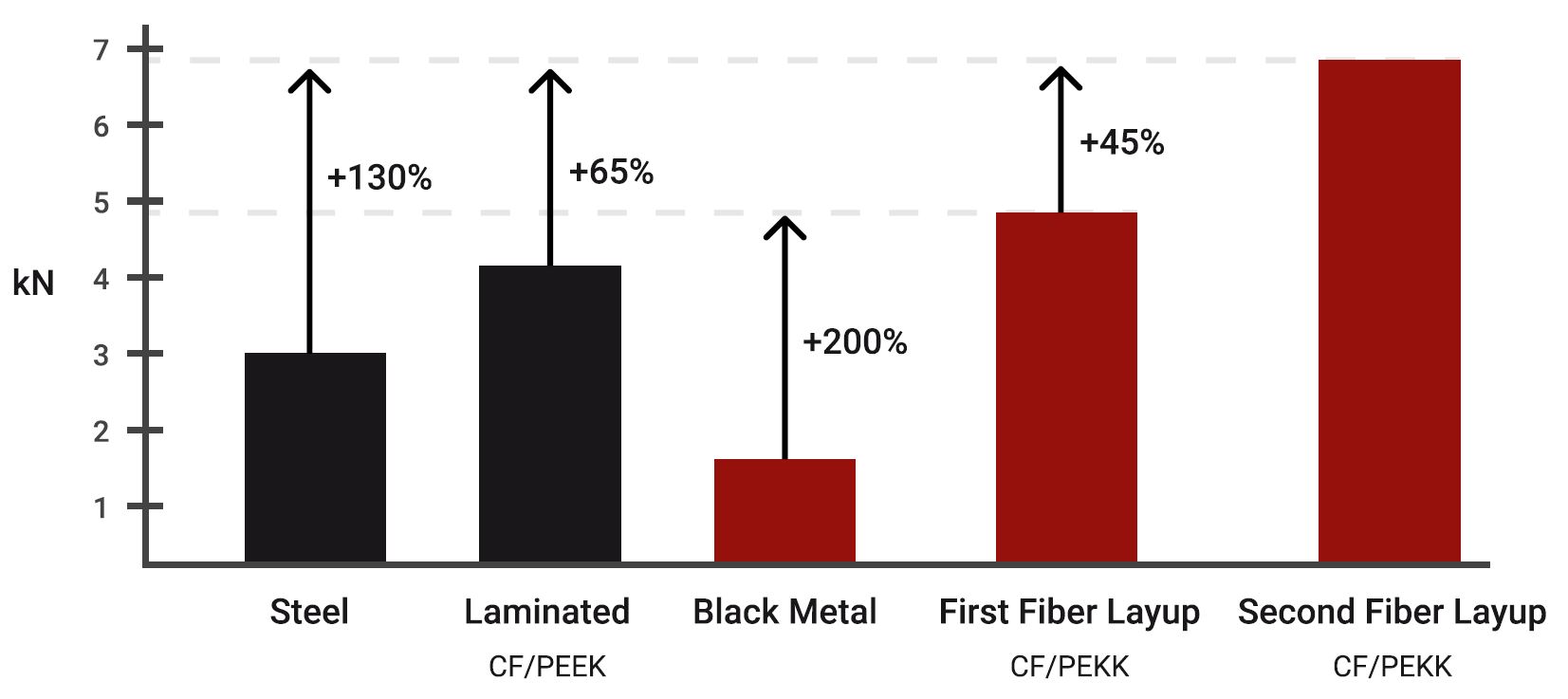
The characteristics and performance of the optimized AFT hinges are compared with the benchmark and the black metal design in Fig. 4. The second fiber layup design weighed only 27.5 grams, 75% lighter than the steel benchmark, while the maximum static load capability was increased more than 200% from 3.0 to 6.9 kilonewtons.
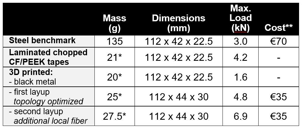
* Metal bushing insert for hinge pin adds 4.2 grams.
** Relative cost at 1,000 parts/year.
Figure 4. Optimized AFT part. The optimized AFT-printed composite parts showed increased failure load and reduced weight compared to the steel benchmark and 3D-fabricated black metal designs. Photo Credit: 9T Labs.
Cost was also evaluated for the first and second fiber layup designs — calculated using Fibrify’s Production Evaluation tool — and found to be half that of the steel benchmark. Each of the designs was imported and then parameters were added — e.g., materials used, print temperature, how many parts produced for machine amortization, etc. — resulting in a cost estimate and breakdown by cost component (materials, process) and subpart.
Further optimization was investigated in a subsequent study and published in the December 2022 paper, “Experimental and numerical analysis of the consolidation process for additive manufactured continuous carbon fiber-reinforced polyamide 12 composites.” A design of the hinge was again printed and consolidated using CF/polyamide 12 (PA12) materials, this time to demonstrate a simulation model for the consolidation/forming process in the Red Series Fusion Module. This model predicts the process-induced deformations of the consolidated part including the effects of temperature, crystallization and porosity. It can predict a final part’s composition, residual stresses and porosity with high accuracy as well as the trend for warpage. It also enables rapid simulation of the Fusion Module process, reduces the number of prototyping iterations and achieves an important step toward “first time right” composite production.
9T Labs continues to advance design and process optimization as it expands the use of AFT to series produce larger and more complex parts and increases the replacement of metal parts with stronger and more affordable composites.
About the Author

Yannick Willemin
Yannick Willemin heads marketing and business development at 9T Labs. He holds a dual Executive MBA from the EBS Universität in Wiesbaden, Germany and the Durham University Business School in the U.K., with an entrepreneurship and blockchain focus. During eight years at SGL Carbon (Wiesbaden, Germany), he gained experience through positions in development, sales, purchasing and innovation strategy. He is passionate about improving lives via engineering technology innovation with a focus on composites.


.jpg;maxWidth=300;quality=90;format=webp)


Related Content

Price, performance, protection: EV battery enclosures, Part 1
Composite technologies are growing in use as suppliers continue efforts to meet more demanding requirements for EV battery enclosures.
Read More
Materials & Processes: Resin matrices for composites
The matrix binds the fiber reinforcement, gives the composite component its shape and determines its surface quality. A composite matrix may be a polymer, ceramic, metal or carbon. Here’s a guide to selection.
Read More
Carbon fiber in pressure vessels for hydrogen
The emerging H2 economy drives tank development for aircraft, ships and gas transport.
Read More
Cryo-compressed hydrogen, the best solution for storage and refueling stations?
Cryomotive’s CRYOGAS solution claims the highest storage density, lowest refueling cost and widest operating range without H2 losses while using one-fifth the carbon fiber required in compressed gas tanks.
Read MoreRead Next

Predicting and mitigating failure in composite parts
Understanding the complexity of composites manufacturing resides in studying the design challenges inherent to fabrication, as much as the physics aspect. To serve this effort, CW introduces a new column, “Predicting Failure.”
Read More
A digital twin to validate SMC performance in suspension structures
High-fidelity, anisotropic behavior material card, integrated with process simulation, structural FEA and validated with CT and physical tests enables optimization proven in award-winning SMC suspension knuckle.
Read More
Composites end markets: Energy (2024)
Composites are used widely in oil/gas, wind and other renewable energy applications. Despite market challenges, growth potential and innovation for composites continue.
Read More