
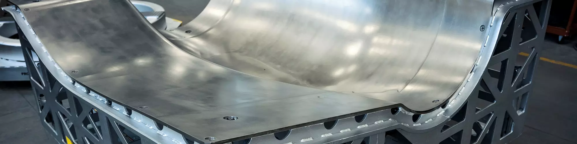


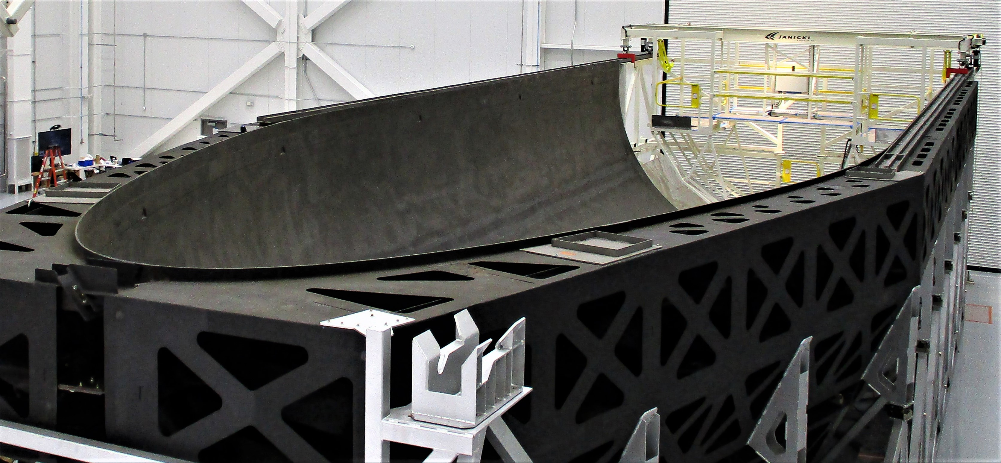
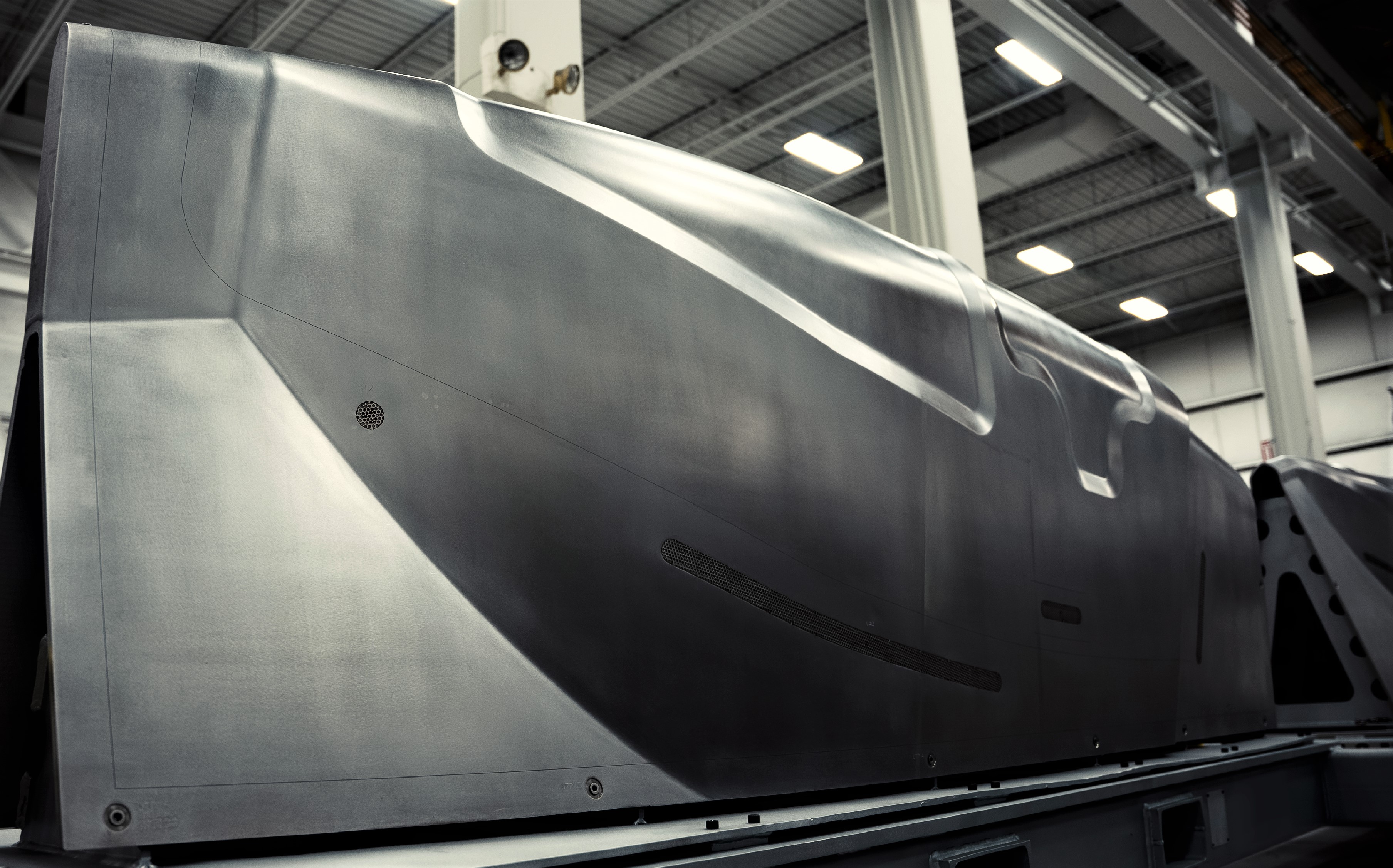
Large composite tool for layup and cure of a fairing. Carbon fiber-reinforced facesheet is paired with carbon eggcrate backup structure for optimal coefficient of thermal expansion (CTE) and thermal performance. Photo Credit: Janicki Industries
“You can make a bad composite part off a good tool. The reverse is not true.” (LaminateLife “Composite Truisms,” 2020).
In my almost 30 years in the composites industry, I have learned (sometimes after much blood, sweat and tears) the profound truth in that statement. While many things can go wrong with a composite part from layup to bagging to cure, the fact stubbornly remains that if you start with bad cure tooling, things will go wrong.


This column focuses on cure tooling (i.e., bond jigs or layup molds) for the main reason that other types of tooling, such as trim or assembly jigs, generally do not see elevated temperatures or high pressure and are therefore greatly simplified in design.
At its most fundamental level, cure tooling is merely a way to provide a pressure reaction surface under temperature to give composites their final shape after cure or consolidation. Getting to that surface is the fun part; there are many ways that tooling design can go pear-shaped. Let’s walk through some of the common pitfalls.
Good composites tooling (as distinguished from composite tooling or tooling made from composite materials) involves many factors that need to be integrated in a holistic design. Design, by its very nature, is an activity of compromise, and for composites cure tooling, the following factors need to be considered and balanced.
Design drivers
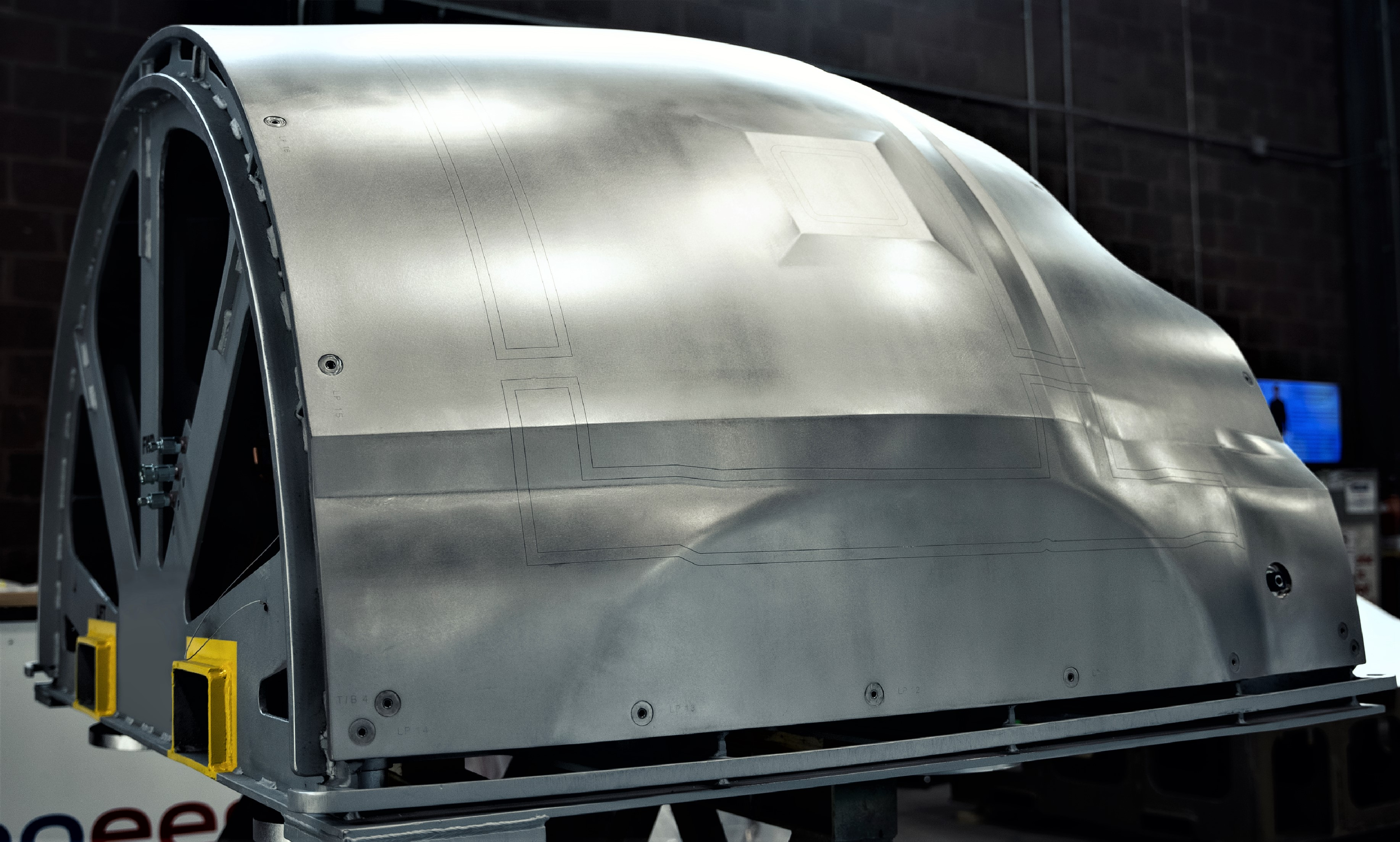
An Invar facesheet is paired with an Invar substructure to reduce CTE effects but maintain durability. Note the edge of ply (EOP) and trim lines etched into the facesheet as well as tooling ball holes around the edges to precisely locate the tool for automated ply layup processes or laser ply projection systems. Photo Credit: Visioneering Composite Technologies
Part geometry, material system, build rate and process drive the overall tooling design. Cure temperatures and pressures push different choices in tooling materials and backup structure layout. In general terms, the lower the cure temperature, the more inexpensive the cure tool can become. The more complex a part, the more expensive the tool. A tool for one or two prototypes will likely be designed very differently than one for an anticipated thousand-article production run.
Moreover, tools that are used with automated processes, such as advanced fiber placement (AFP) or automated tape layup (ATL), may require additional backup structure or thicker facesheets to handle the pressure point loads from the roller head and/or features to integrate with headstock/tailstock fittings if the tool needs to rotate.
Material choices
There are a number of material choices that can be used for composites cure tooling, but they generally fall into three main families: low-cost metals such as aluminum or plain carbon steel; high-end nickel steel alloys such as Invar; and composites.
Each of the three families have their uses and need to be evaluated against all of the other required properties listed here. Also up-and-coming are additive — metal and polymer — manufactured tools, which have their own set of advantages (rapid design changes, no tools to make tools, almost limitless geometries, etc.) and challenges (high thermal expansion, poor durability, vacuum integrity, etc.).
Thermal performance
Cure tools must be able to hold their shape up to cure temperature and even beyond to account for cure cycle overshoots. Coefficient of thermal expansion (CTE) is an important consideration, especially for larger parts; how much the tool grows during heat-up (and shrinks during cooldown) can significantly impact dimensional control of the part and/or quality.
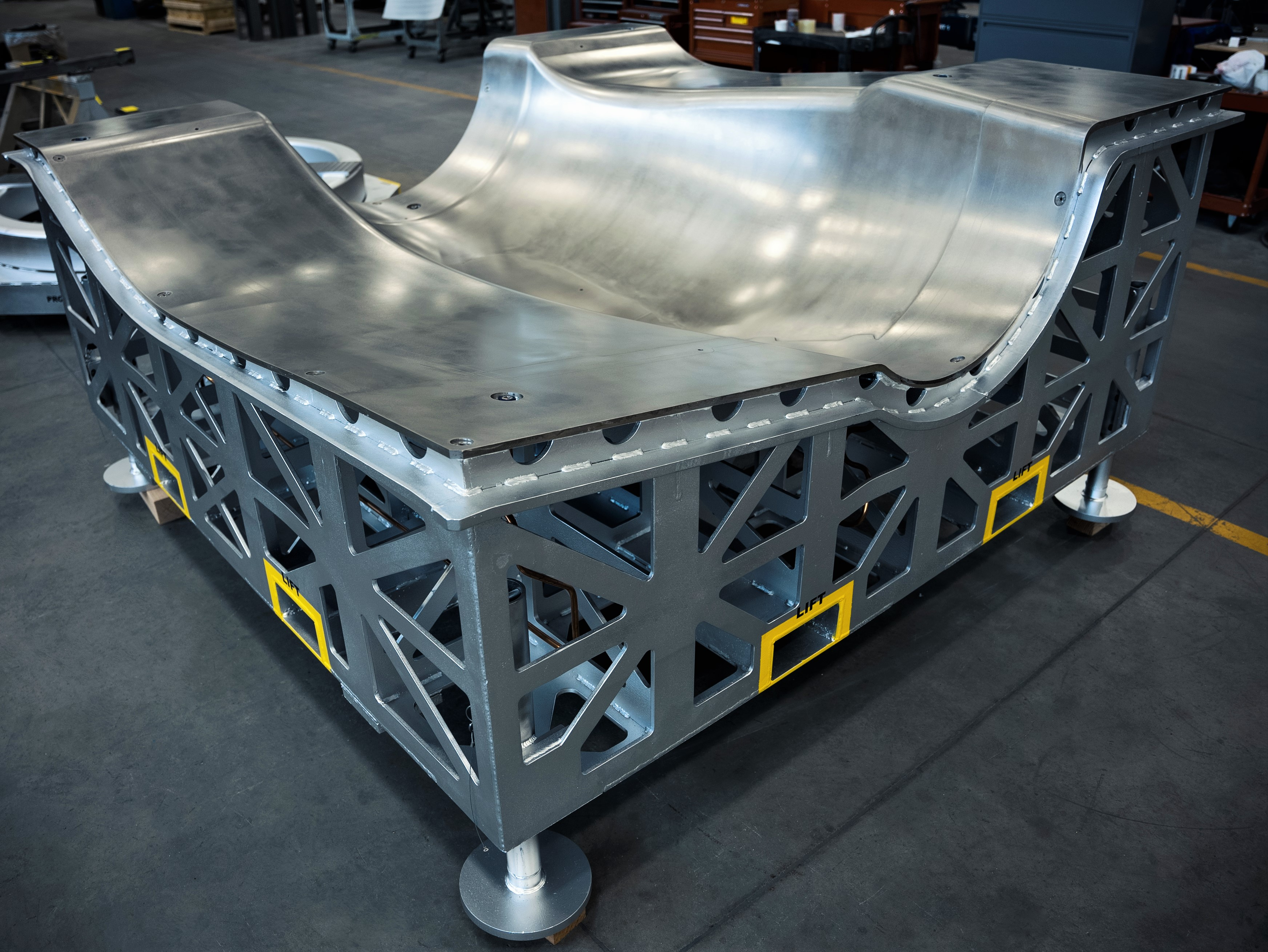
Invar “eggcrate” structure to enable good gas flow. Facesheet stiffeners also have half-circle holes to help with thermal uniformity. Photo Credit: Visioneering Composite Technologies
For example, trapped details can experience delamination due to shrinkage of high CTE tooling during cooldown after cure. Thermal uniformity of the tool is important to avoid hot/cold spots — this means an open backing structure to enable gas flow. Tools need to undergo thorough heat surveys to confirm uniform heating before being released to production.
Dimensional compensation
Tooling must be designed so that the final as-cured part conforms to dimensional requirements. CTE is an important factor as well as the internal stresses of the cured composite, which can lead to effects such as spring-in. In metals, shapes need to be over-formed because they will “spring back” — on the other hand, composites need to be under-formed because they exhibit the opposite behavior, springing “in” after cure. Under-forming is usually on the order of 1.5 degrees as a rule of thumb, but it is material- and cure cycle-dependent. In recent years, thermal modeling of parts and tooling during cure has significantly improved first-time tool design quality.
Facesheet and backup structure
Tooling should be designed for minimal weight (ease of transportation, faster heat up, etc.). The facesheet (the portion of the tool actually in contact with the composite part) needs to be thin to speed cure cycles and reduce costs, but thick enough to maintain contour under pressure.
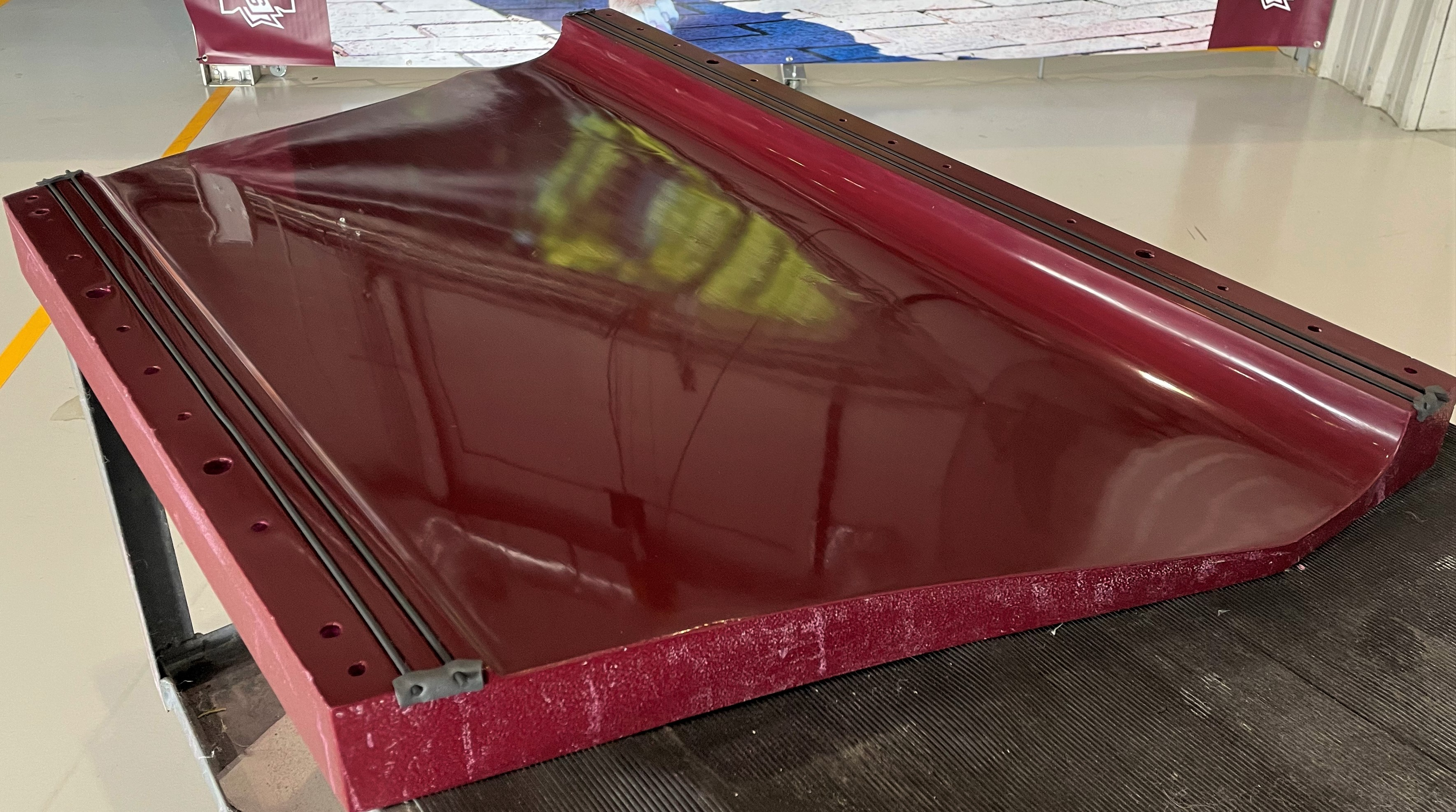
Durable and inexpensive low carbon steel tool with pocket features for ply build-ups or honeycomb. Note the integrated features for distributing vacuum. Photo Credit: Visioneering Composite Technologies
The facesheet is the key part of the cure tool and needs to be able to resist cuts and scrapes. Any nicks or scratches on it must be able to be easily repaired or blended out. Additionally, the facesheet has to take numerous thermal cycles without degrading or deforming, and at the same time be compatible with the mold release and withstand the demolding and cleaning/reapplication cycles of mold release.
Backup structure (supporting the facesheet), such as “eggcrate,” needs to be spaced close for rigidity and dimensional control, but far away enough to reduce weight (and cost) and improve gas flow.
Vacuum integrity
The facesheet of the tool must prevent any gas leak paths (which can cause porosity) from reaching the composite layup. In metallic tooling, this generally is not a major issue, although leaks can occur at welded joints. For tooling made from composites, porosity in the facesheet or surface porosity can make vacuum integrity more challenging.
Surface profile/smoothness
Depending on the tooling approach, the tooled surface of the part may be outer mold line (OML) or inner mold line (IML). IML-tooled parts need an appropriate surface profile to mate with the substructure; OML-tooled parts need smoothness to reduce drag.
Although tight tolerances might seem an easy way to reduce risk, it also greatly increases cost. For smoothness, tolerances twice as tight as the final desired part smoothness are typically levied against the tool to account for in-process variation and degradation of the tool over time.
Smoothness of the layup surface is important. Reactive additive manufacturing (RAM) made this thermoset layup tool. Additive manufacturing (AM) of cure tooling can work well for prototype and proof-of-concept rapid manufacturing trials. Photo Credit: Mississippi State University, Advanced Composites Institute
Cost
The cost of the tool will be spread across the production run of the part. Therefore, the more parts being built on the tool, the less the influence of tooling on part cost and the more that can be invested in better (lower CTE) and more durable tooling.
Conversely, for prototyping and one-two part runs, tooling costs must be very carefully controlled or significant additions to part cost may be incurred. This may drive the tooling choices to lower durability materials and/or higher CTEs, which demand more rigorous design to ensure proper part geometry.
Ultimately, time (and budget) invested up front to proactively address each of the above issues will pay large dividends during production with robust processing and low scrap rates.
About the Author

Gary Bond
Gary Bond is a private pilot, a SAMPE Fellow and a Solvay Technical Fellow, providing technical service support to Solvay customers who are facing composites manufacturing challenges. Prior to retirement, he worked with Boeing for 26 years as a composites M&P Technical Fellow. You can follow him on LinkedIn for LaminateLife — all things composites, aviation and really bad dad jokes.


.jpg;maxWidth=300;quality=90;format=webp)


Related Content

Materials & Processes: Tooling for composites
Composite parts are formed in molds, also known as tools. Tools can be made from virtually any material. The material type, shape and complexity depend upon the part and length of production run. Here's a short summary of the issues involved in electing and making tools.
Read More
Composite prepreg tack testing
A recently standardized prepreg tack test method has been developed for use in material selection, quality control and adjusting cure process parameters for automated layup processes.
Read More
ASCEND program update: Designing next-gen, high-rate auto and aerospace composites
GKN Aerospace, McLaren Automotive and U.K.-based partners share goals and progress aiming at high-rate, Industry 4.0-enabled, sustainable materials and processes.
Read More
JEC World 2022, Part 3: Emphasizing emerging markets, thermoplastics and carbon fiber
CW editor-in-chief Jeff Sloan identifies companies exhibiting at JEC World 2022 that are advancing both materials and technologies for the growing AAM, hydrogen, automotive and sustainability markets.
Read MoreRead Next

Proper application of semi-permanent mold release systems
Performing regular maintenance of the layup tool for successful sealing and release is required to reduce the risk of part adherence.
Read More
Digitizing tools for composites production
Alpex Technologies focuses on industrialization, process and part intelligence and biocomposites in its next generation of tooling systems.
Read More
Composites end markets: Energy (2024)
Composites are used widely in oil/gas, wind and other renewable energy applications. Despite market challenges, growth potential and innovation for composites continue.
Read More