
Skinning the F-35 fighter
Fastening the all-composites skin on the Lightning II requires machining and drilling technology that is optimized for cost-efficiency.


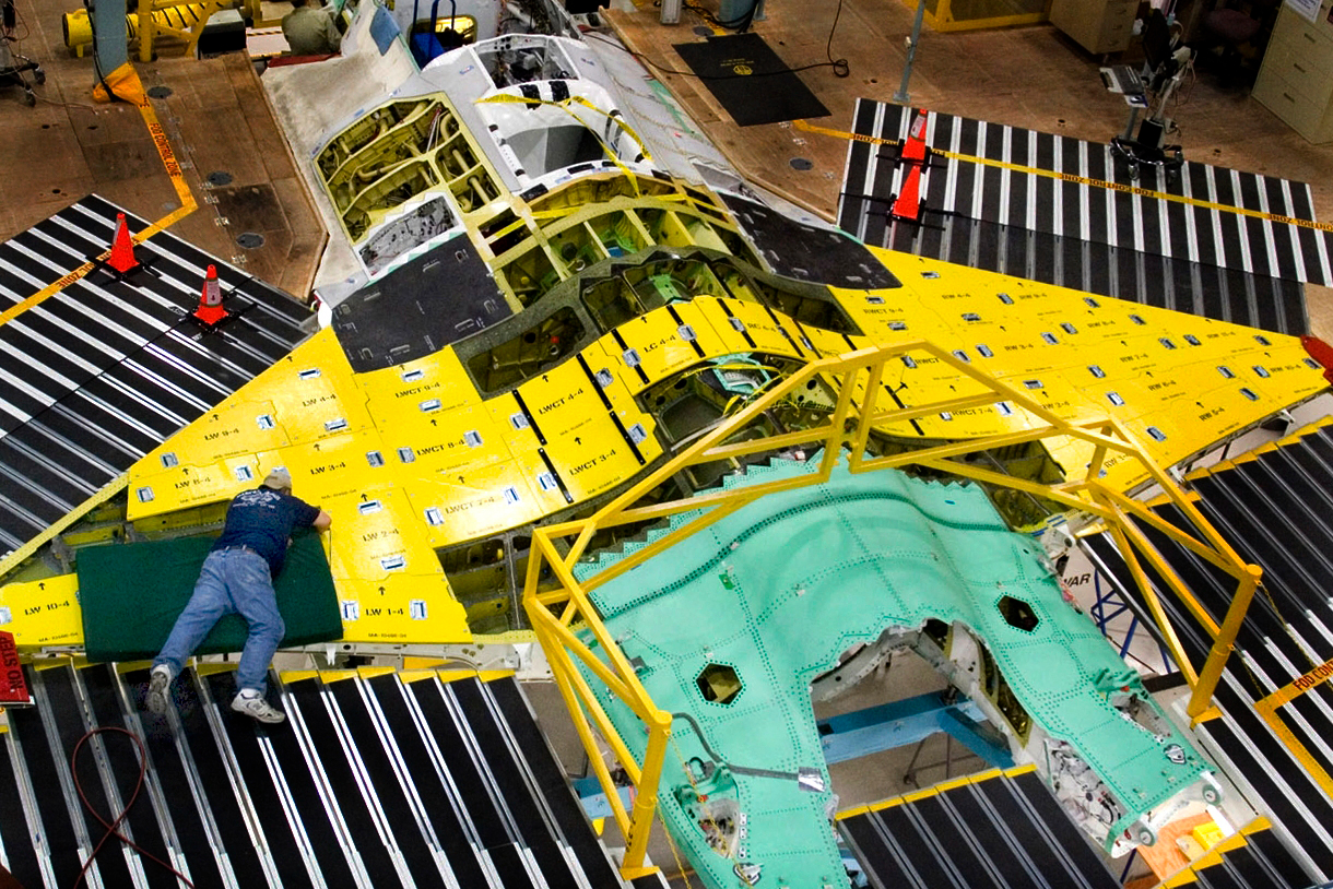
This F-35 on the Lockheed Martin assembly line inside the Fort Worth facility awaits the carbon fiber-reinforced skin that will sheath the finished craft’s fuselage and wings. Source: Lockheed Martin
When the Obama Administration announced earlier this year that the F-22 fighter jet program would be cut from the 2010 U.S. Department of Defense (DoD) budget, sentiment among Lockheed Martin employees at the company’s Fort Worth, Texas, U.S., facility was bitter and sweet. The cavernous plant — 1 mile/1.6 km long and 0.25 mile/0.4 km wide — is the assembly point not only for the F-22, but also the forthcoming F-35 Lightning II, an unscathed survivor of the DoD’s budget-cutting process.
From a budget perspective, the DoD’s preference for the F-35 — or Joint Strike Fighter (JSF) — is understandable. Its flyaway cost of $83 million (depending on variant), is a relative bargain compared to the F-22’s $143 million. And co-development of the plane with cost-sharing partner countries ensures a long orders list — Lockheed Martin plans to deliver more than 3,000 F-35s through 2036.


Unlike the air-to-air F-22, the F-35 is a multirole craft, designed for air-to-air and the air-to-ground combat that pilots are more likely to face. The multirole design makes the F-35 highly adaptable. It comes in three variants: the F-35A for conventional takeoff and landing (CTOL), the F-35B for short takeoff and vertical landing (STOVL), and the F-35C for carrier-based landing (CV). Multirole capability enables it to replace the F-16, A-10, AV-8B and the F-18 in the U.S., and the Sea Harrier and GR.7 in the U.K. In the U.S., it will complement existing F-22 and F-18E/F fleets. From the manufacturing perspective, the variants share a common design for more than 20 of %the airframe structure, thus reducing program cost.
Dozen-year development
Lockheed Martin is the prime contractor for the F-35, having won the bid in October 2001. Northrop Grumman and BAE Systems are the principal partners on the project. The three companies are more than halfway through a 12-year System Development and Demonstration (SDD) phase, which includes production and testing of 19 aircraft. Composites have been a major part of the manufacturing effort.
Northrop Grumman makes the center fuselage at its Palmdale, Calif., U.S., plant, and the wingskins at its Magna, Utah, U.S. facility; BAE Systems produces the aft fuselage and tails at its facility in Samlesbury, U.K.; Lockheed Martin makes the forward fuselage and assembles finished aircraft in Fort Worth. The first F-35, a CTOL variant, flew for the first time on Dec. 15, 2006. All SDD aircraft are in production or on the flight line for testing; the first 14 production-model F-35s have started assembly.
CW was recently invited to tour the massive Fort Worth facility and see firsthand how composites are being shaped for this next-generation fighter.
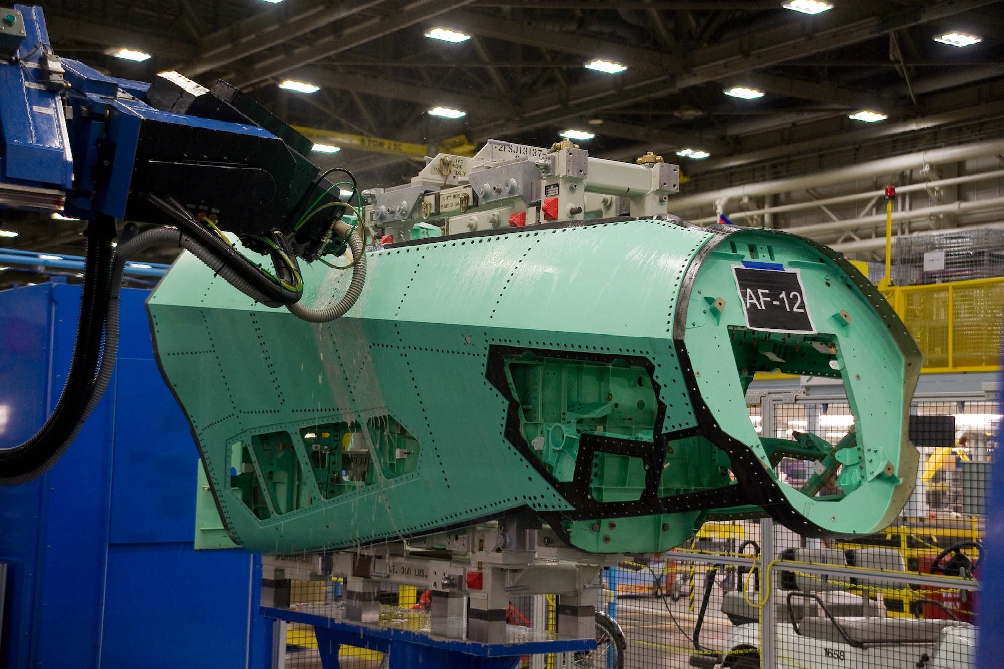
An automated drilling system bores one of the 1,500 holes that will accommodate fasteners in the forward section of the F-35’s forward fuselage. Source: Lockheed Martin
Big job on a tight budget
One of the challenges of manufacturing a fighter that is marketed, in part, as budget-friendly, is that special care must be taken to cost-optimize every component of the plane. This is perhaps most true for the F-35’s carbon fiber composites, which comprise approximately 35% of the structural weight and most of the visible surface on the fighter. And with fuselage sections, wings, and tails coming from different suppliers, the biggest challenge Lockheed faces is managing the aircraft’s composite skin thickness.
Don Kinard, technical deputy, JSF Production Operations, at Lockheed Martin Aeronautics, says the company spent considerable time evaluating a variety of material types — composites, aluminum, titanium and steel — for the aircraft frame and skin to establish a cost/benefit ratio that was the most cost-effective.
“Can we make an all-composite fighter jet?” asks Kinard. “Sure, but we don’t do something just because we can. Everything is a cost-benefit analysis. Where are the best places to most efficiently use composites?” He notes that composite substructures were evaluated for the F-16, F-22 and F-35, but didn’t provide the weight savings needed to justify cost. “We needed to save a lot more weight for composite substructures to make sense,” he says. Also, he notes, in composites substructures, “z-directional properties are the problem. The strength of resin will have to be significantly improved. There’s a lot to overcome.”
As a result, composites on the F-35 are used almost exclusively in skin applications. Kinard notes that Lockheed, wherever in-flight service temperatures allow, uses carbon fiber/epoxy from what as, at the time, Cytec (now Syensqo, in Alpharetta, Ga., U.S.). However, much of the plane’s skin requires higher heat resistance, where Syensqo’s CYCOM 5250-4 bismaleimide (BMI) is used. Although Lockheed is evaluating the new crop of out-of-autoclave (OOA) resins for special applications, Kinard foresees no near-term changes in the matrix.
During the F-35’s SDD phase, production of skin sections has differed, depending on the supplier, the part’s complexity and cost effectiveness. Northrup Grumman in Utah, for instance, uses automated fiber placement (AFP) technology to produce many of the wing composite parts.
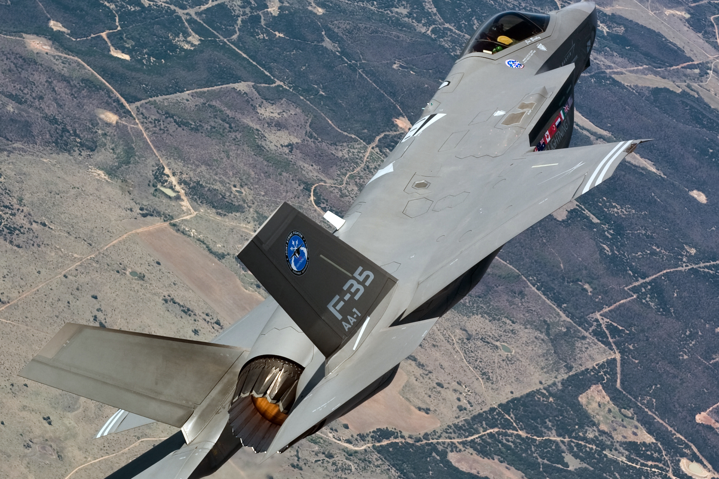
CTOL version of the F-35. Source: Lockheed Martin
Lockheed internally chose to produce the forward fuselage skins using hand layup. As the F-35 enters production, more domestic and international aerospace suppliers will be involved with composite part production, including Leonardo (Rome, Italy), Kongsberg Defence Systems (Kongsberg, Norway) Terma A/S (Grenaa, Denmark), Turkish Aerospace Industries (Istanbul, Turkey) and others. “We’re leveraging the capacity of the entire world in terms of composites fabrication,” contends Kinard.
Kinard says much of his and Lockheed’s F-35 composites energy is focused on managing the thickness of the composite skins. This is accomplished via addition and subtraction of composite plies based on careful metrology in some cases and by machining of parts in other cases.
Kinard says consistency of composite skin thickness is critical for the weight-, performance- and cost-conscious F-35. Lockheed and its partners use two methods to make sure skins meet thickness targets: Machining or post-mold ply additions.
At Lockheed Martin in Fort Worth, forward fuselage skins are hand-layed on Invar 35 tooling and cured in one of three large autoclaves built by Taricco Corp. (Long Beach, Calif.). Sacrificial plies cured into the laminates are subsequently machined to control thickness of the skins. At Northrop Grumman, fiber-placed skins for the wing are cured and, following cure, skin thickness is precisely measured using a process developed by Lockheed Martin’s Manufacturing Technology & Production Engineering personnel. If needed, additional plies are layed up and the entire structure is cured a second time in a process called cured laminate compensation (CLC). “The Holy Grail here is to control thickness,” he says, but points out that cost dictates the strategy for doing so.
Massive machining center
Located in the center of Lockheed’s sprawling Fort Worth facility is a key component of that strategy: The F-35’s machining and drilling operation. Among the largest built by Dörries Scharmann Technologie GmbH (DST) (DST, Mönchengladbach, Germany), the 10-meter by 30-meter (33 feet by 99 feet) machining center at its heart machines and drills some of the F-35’s forward fuselage skins, wingskins and other composite parts.
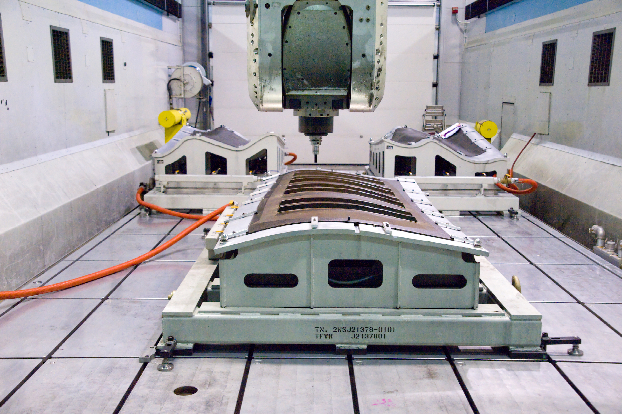
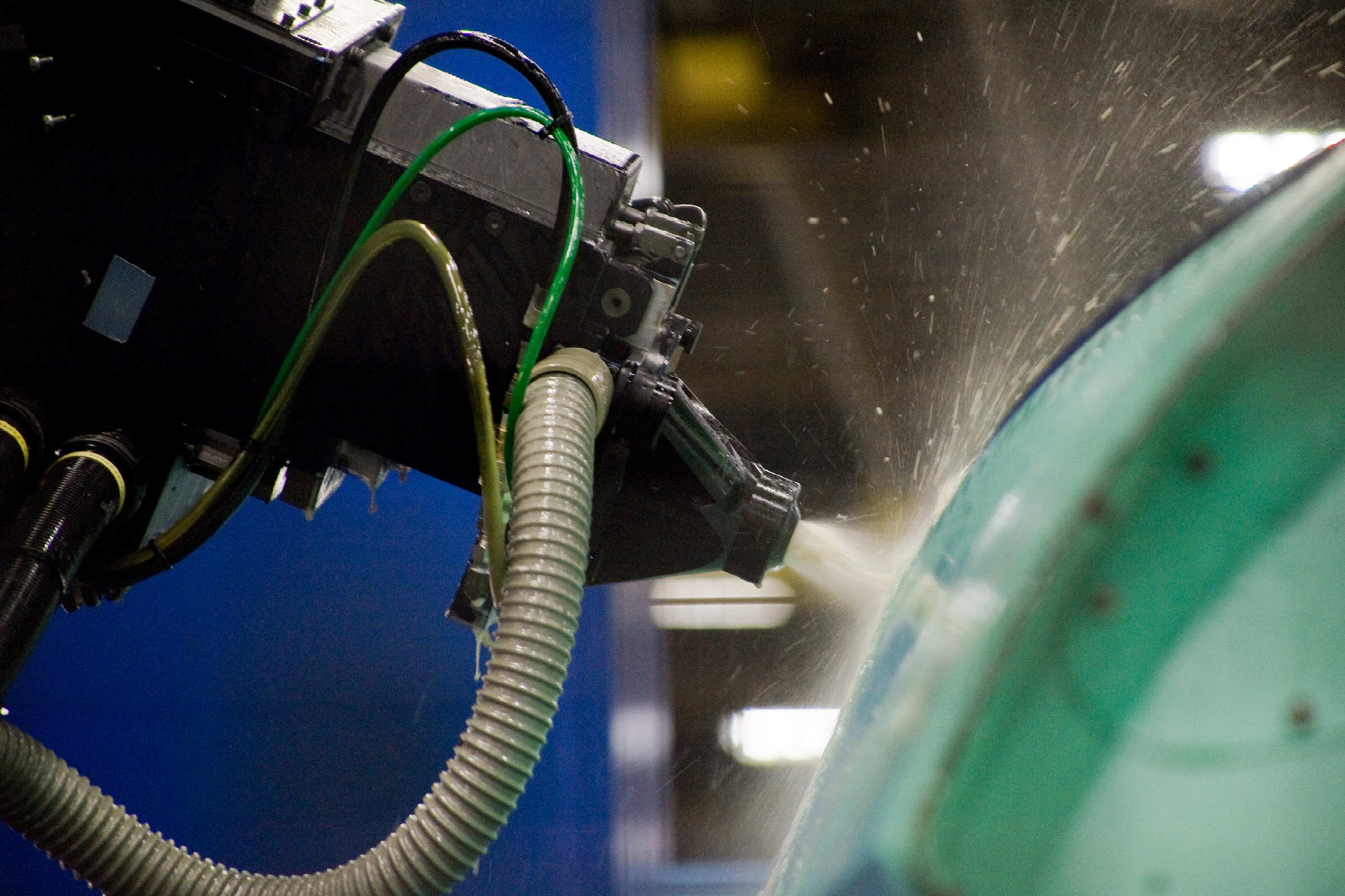
The DST machining center removes sacrificial material to help F-35 skins meet tolerance targets. Source: Lockheed Martin
“Trimming and machining are a very big deal for us on this program,” Kinard admits. The DST system automates most work that, historically, has been performed manually. Again, engineers from the Manufacturing Technology group were instrumental in bringing these systems online and developing reliable machining processes.
The DST system uses a flexible overhead gantry (FOG) with automatic tool changer to handle trimming, drilling and compression routing. Most of the machining done here is on the forward fuselage skins. (Wingskin machining has been transferred back to Northrop Grumman in Utah, which contracts with Janicki Industries, Sedro-Woolley, Wash., U.S., for the machining.)
The forward fuselage skins take about eight hours to machine, mainly because each skin section requires several setups. The machine works on both sides of the structure, with one head machining the inner mold line (IML, to control thickness) and the other drilling holes and trimming the edge of part (EOP). The wingskins, when they were machined by Lockheed, usually took less time to machine because there is no IML machining to control for thickness — wing parts use the CLC process to meet thickness parameters.
Most of the work in the DST machining center is handled by diamond-coated carbide tooling supplied by AMAMCO Tool (Duncan, S.C., U.S.; see sidebar, below). AMAMCO designed the DST router especially for this application.
Following machining, all composite structures are rolled out of the DST machine and into an adjacent room that houses a Carl Zeiss MicroImaging Inc. (Maple Grove, Minn., U.S.) metrology system, “the largest high-tolerance measuring system in the world — as far as we know,” says Kinard. It’s here that the skins’ dimensions, edges, and holes are checked for accuracy. In operation since June 2008, the MMZ-B Plus gantry coordinate measuring machine’s expansive measuring envelope — 5 meters by 16 meter by 2.5 meters (16 feet by 52 feet by 8 feet) — accommodates the wingskins of the F-35, as well as aerodynamic tools, wind-tunnel models, 1:1 modules and other airframe elements.
Lockheed Martin also inspects its composite structures for voids and other internal flaws with a nondestructive laser ultrasonic inspection system (laser UT) that it developed in-house. The system’s 400-MHz laser is directed toward the composite structures; signals from that laser returned to a sensor reveal voids, cracks, delamination and other flaws in the skins. With an operating speed of 6 ft2/min (0.56m2/min), Kinard says it’s 10 times faster than traditional squirter inspection systems and is an indispensable part of the F-35 manufacturing process. Lockheed Martin patented the system, but licensed the technology to PaR Systems Inc. (Shoreview, Minn., U.S.).
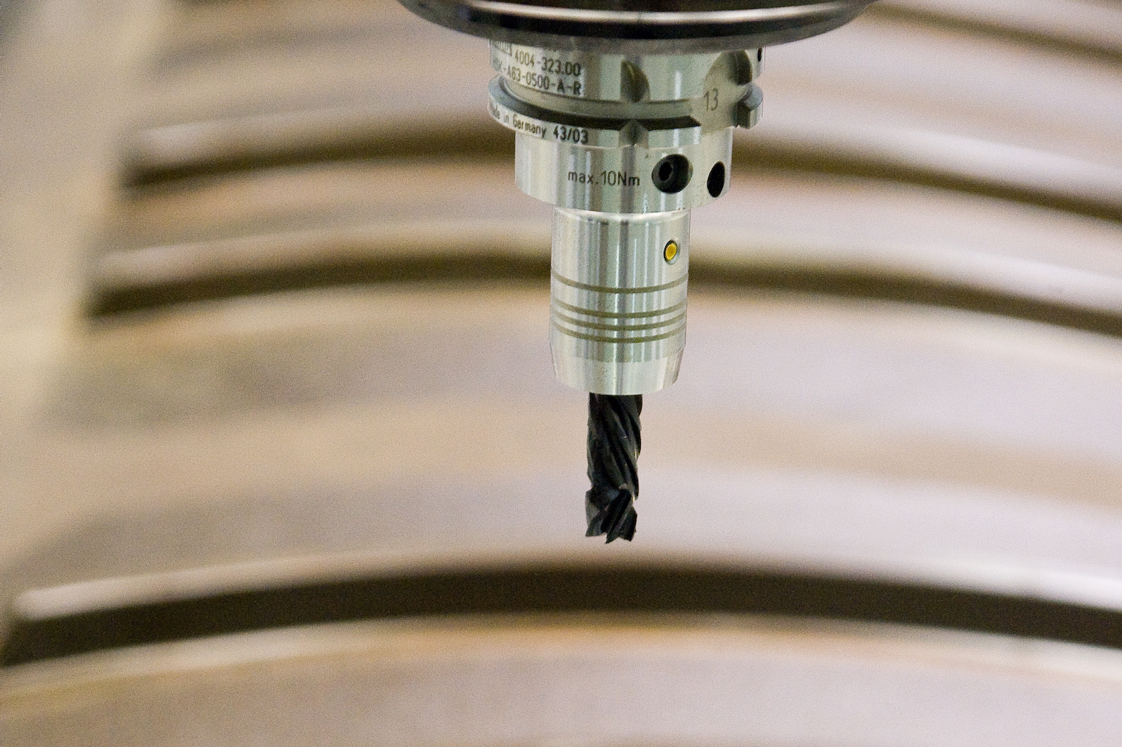
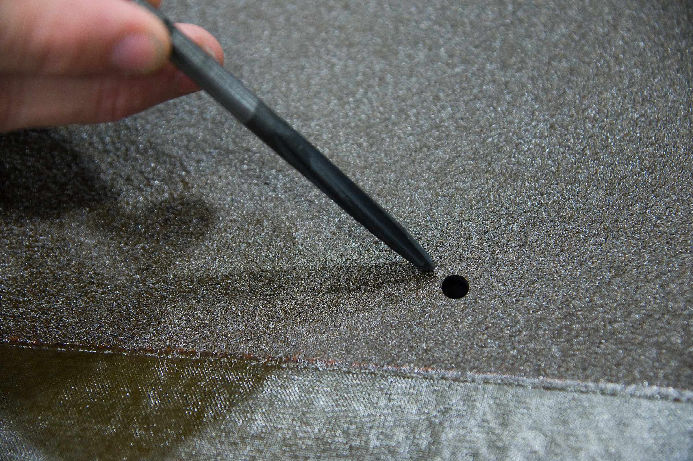
Close-up of drilling head acting on carbon fiber/BMI skin of F-35. Source: Lockheed Martin
Drilling, drilling, drilling
Once the composite skins are molded, trimmed and inspected, they are ready for attachment to constituent airframe structures. This is accomplished with fasteners drilled through the skin and into the frame at predetermined locations. Management and optimization of drilling on the weight-sensitive F-35 has become a significant effort, and part of the SDD process involves evaluation of drills, drilling tool geometry, tool efficiency, tool life, hole-drilling time, cost per hole drilled and other variables.
The F-35 is already off to a good start with drilling: Glenn Born, manufacturing engineering senior staff at Lockheed Martin Aeronautics and one of the resident drilling gurus at the Fort Worth facility, says the F-35 has less than 50 cutting tool drawings for the entire craft. The F-16, by comparison, had 9,000. This reduction is attributed mostly to standardization efforts integrated into both the F-22 and F-35 programs to address common hole sizes, fastener reduction and common assembly methods for processing composite/metallic structures. It also helps that composites drilling technology is evolving rapidly.
There are three types of drilling being evaluated on the F-35: manual, powerfeed and automated (numerically controlled), although most drilling at Lockheed is automated. In most cases, the F-35 drilling method is “stacked,” which means that the composite skin is placed on the substructure and a hole is drilled through the skin and the substructure simultaneously with a single drill tool that drills, reams and countersinks in one step. One of the more impressive drilling operations on the F-35 involves the forward fuselage, which has 750 holes on each side drilled into it by an automated gantry-style head.
Born says the substructure provides backing for the skin and, therefore, helps prevent delamination. The method’s disadvantage is the amount of time it takes to produce one hole — about 30 seconds, depending on skin thickness. “It could expedite the assembly process if we drill the skin and substructure separately,” Born admits, “but tolerances demand stack drilling. This is especially challenging when parts are made elsewhere and then mated at Lockheed Martin — with the reduced bolt-to-hole clearance at maximum material condition, there’s too much opportunity for interference.”
Wingskins are stack-drilled by an automated Cincinnati Milicron gantry system. Subsequently, the F-35 team uses a Virtek Vision International Inc. (Waterloo, Ontario, Canada) laser projection system to project fastener part numbers onto the surface of the wingskins during fastener installation to eliminate the need to refer to complex drawings. Where automated drilling is not possible, manual drilling involves a template attached to the skin that shows where to drill holes. Kinard reports that use of projection systems has great potential to reduce labor and task spans.
Tracking a tool-change threshold
Given the decision to use stack drilling, Lockheed has focused on developing parameters to measure hole quality and tool life, mainly to assess the cost of tool wear and subsequent reduced drilling speed against the cost of a new and faster tool. Most drill motors used at the Fort Worth facility employ air and hydraulics. The sharpness of the tool, however, dictates drilling speed. As the cutting tool dulls, the process takes longer.
“Our powerfeed system will eventually measure the length of time to drill. When the threshold is reached, an indicator light will notify the operator to change the tool,” says Born. Ultimately, he says, Lockheed is looking for good diameter tolerance and exceptional process control that make noncompliant holes virtually nonexistent. The Cpk (statistical measure of process capability) target for F-35 hole quality is 1.3; Born says Cpk right now is about 1.0 and improving. “Our first articles have quality better than some mature programs,” he contends.
All of these trimming and machining systems and drilling processes are being evaluated for efficiency, cost, speed and other variables to determine best practices for the entire F-35 composites production process. Lockheed Martin has established a drilling/machining Center of Excellence at the Fort Worth facility to continue development of cutting tools and technologies. And if the lifespan of the F-35 holds true, it appears that Lockheed Martin and all of its suppliers have decades of composites optimization and management ahead of them, as well.
Proving tool geometry and materials
When Lockheed Martin first began assessing router and drill tools for F-35 production in its DST machining center (Dörries Scharmann Technologie GmbH, Mönchengladbach, Germany), it used a polycrystalline diamond (PCD) router with braised diamond inserts. It featured straight flutes and produced too much delamination on the composite structures, forcing rework and increased tooling costs. Further, the tools lacked the durability needed for this demanding application — one 0.375-inch/9.5-mm-thick wingskin section typically required 24 tools to rout (this was when the F-35 had one large, continuous top skin to cover both wings; current design features three top skins).
AMAMCO's diamond-coated router tool. Source: Lockheed Martin
Lockheed turned for help to the National Center for Defense Manufacturing and Machining (NCDMM, Latrobe, Pa., U.S.), a research and development consortium of partner companies that work with defense contractors to optimize manufacturing methods. Lockheed eventually adopted a diamond-coated compression router supplied by NCDMM member AMAMCO Tool (Duncan, S.C., U.S.), and tested the tool on the DST machining center.
Andrew Gilpin, AMAMCO’s business development manager, says results of tests with the diamond-coated composite tool were promising: The number of tools required to machine an entire wingskin was reduced from 24 to 2, and the path a single tool could machine in a composite was increased from 9 to 57 linear feet (2.7 to 17.4 meter). Gilpin says the key to the tool’s success is in its design, which uses two opposing flutes (see top photo) that sandwich composite layers together, rather than pulling them all in one direction: “Like scissors, not a shovel,” he says. “It gives a nice, clean shearing effect.”
This AMAMCO diamond-coated drilling tool provided a useful life of 1,200 holes compared to the 275-hole life of a competing PCD tool. Source: Lockheed Martin
AMAMCO developed the geometries and manufactures the tools. The diamond coating, 12µ thick, is provided by Diamond Tool Coating LLC (North Tonawanda, N.Y.). Lockheed Martin was so satisfied with the AMAMCO tool that it approved it for production and qualified it with ship-to-stock status for use on the F-35.
Other AMAMCO diamond-coated tools are currently used by Lockheed in other drilling applications on the F-35. Gilpin says that in one application, an AMAMCO diamond-coated tool provided a useful life of 1,200 holes (bottom photo), compared to the 275-hole life of a competing PCD tool that was drilling a hole one-third the depth of the AMAMCO diamond-coated tool. Although Lockheed reports that the diamond-coated tools run at about 8,500 rpm, compared to 5,000 for PCD tools, Gilpin says that diamond-coated tools, on the whole, turn slower than PCD tools, but provide a faster feed rate. Lockheed is evaluating a range of AMAMCO tools, ranging in diameter from 0.125 to 0.4 inch (3.2 to 10.1 mm).


Related Content

Industrializing additive manufacturing in the defense/aerospace sector
GA-ASI demonstrates a path forward for the use of additive technologies for composite tooling, flight-qualified parts.
Read More
Plant tour: Airbus, Illescas, Spain
Airbus’ Illescas facility, featuring highly automated composites processes for the A350 lower wing cover and one-piece Section 19 fuselage barrels, works toward production ramp-ups and next-generation aircraft.
Read More
Combining multifunctional thermoplastic composites, additive manufacturing for next-gen airframe structures
The DOMMINIO project combines AFP with 3D printed gyroid cores, embedded SHM sensors and smart materials for induction-driven disassembly of parts at end of life.
Read More
Ceramic matrix composites: Faster, cheaper, higher temperature
New players proliferate, increasing CMC materials and manufacturing capacity, novel processes and automation to meet demand for higher part volumes and performance.
Read MoreRead Next

Robotic computed laminography brings X-ray CT resolution to large composite structures
Omni NDE collaborative robots, X-ray end effectors and Voxray’s reconstruction approach enables 5-micron inspection of aerospace parts without size constraints.
Read More
Thermoplastic composite materials and processing interactions
Selection of product material formats and their interactions with various process methods heavily influence a final TPC part’s properties and fabrication options.
Read More
Cutting engine weight via thermoplastic composite guide vanes
Greene Tweed replaces metal stator vanes with its DLF material co-molded with a metal leading edge that meets performance, cost and high-rate production targets while cutting 4 kg per engine.
Read More