
Regional buses boost CFRP in alternative energy
Diesel-to-fuel-cell bus conversions signal potential niche for composites in public transit powertrains.
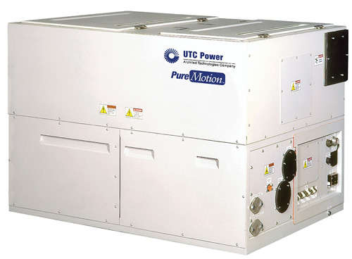
UTC's 1,984-lb/900-kg “box” contains the fuel cell, electronic controls, and the hydrogen fuel, air and water management systems. To make the diesel-to-fuel-cell transition as seamless and easy as possible for the bus manufacturer, all connections to the fuel cell are on one face of a unit that can be installed in the space typically occupied by a diesel engine. Source: UTC
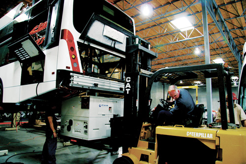
The UTC PureMotion Model 120 fuel cell is installed in a Van Hool A330 bus chassis. Source: UTC
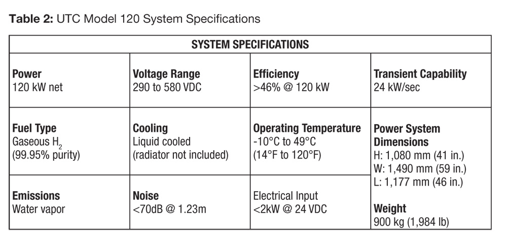
Table 2: UTC Fuel Cell System Specifications.
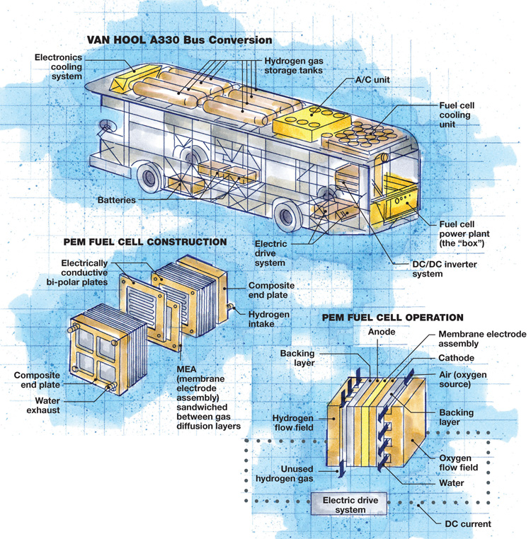
Illustration: Karl Reque
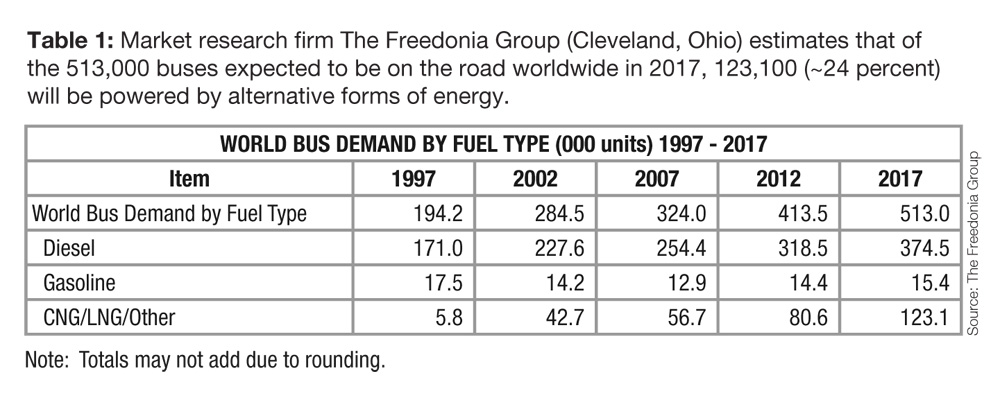
Table 1: World Bus Demand By Fuel Type
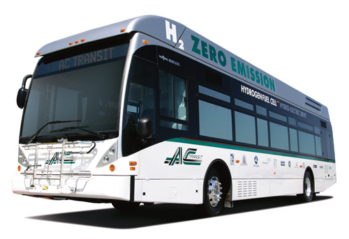
A modified Van Hool A330 FC bus, ready for hydrogen fuel cell-powered electric service. Source: ABC


Although the invention of the first fuel cells for converting hydrogen to electricity is generally credited to the Welshman Sir William Grove in 1839, the first practical use of what is now known as the fuel cell was in 1965 by the U.S. National Aeronautics and Space Admin. (NASA) in its Gemini and Apollo human spaceflight missions. Fuel cell power captured the imaginations of auto engineers back in the late 1990s, in part, because the technology produces no harmful emissions. But since then — a handful of concept demonstrators, such as Ford’s small Focus FCV, notwithstanding — it’s been eclipsed by plug-in and hybrid electrics. The absence of a hydrogen fuel delivery infrastructure has raised considerable doubt about its feasibility in passenger cars.
No such doubts, however, plague the public transit sector. “Commercial fuel cell buses are past the point of determining feasibility. They are doing the work, collecting quarters every day in revenue service,” reports Ken Stewart, VP of transportation for UTC Power (South Windsor, Conn.). In fact, a fleet of six regional buses for which UTC provided the fuel cells already has accumulated more than 300,000 miles in commercial service over the past four years. Because the buses can travel 300 miles on one load of fuel — more than a day’s work — access to fuel is a nonissue: “The … buses all come home to the same place at night, to their depot,” he points out. Refueling, therefore, is done safely and efficiently at a central location. (For facts and figures on buses powered by alternative forms of energy, see Table 1, at right.)


Manufactured by Van Hool NV (Lier, Koningshooikt, Belgium) and funded, in part, by grants from the U.S. Federal Transit Admin.’s fuel-cell program, the buses are distributed in the U.S. exclusively by ABC Companies (Faribault, Minn.). They currently are operated in Connecticut by CT Transit (Hartford); in California by SunLine Transit (Thousand Palms) and AC Transit (Oakland); and in Belgium between Lear and Antwerp. Sixteen more are on order.
Bus conversion contains cost
Notably, the fuel cell program did not require an entirely new bus design. Van Hool was able to modify its standard Model A330. Its diesel-drive components were replaced with an electric drive system built by Siemens AG (Berlin and Munich, Germany) and the powerplant compartment was extended across the entire rear width of the vehicle to accommodate the 1,984-lb/900-kg “box” (see photos, at right) that contains the fuel cell, electronic controls, and the hydrogen fuel, air and water management systems. “The goal is to make the transition as seamless and easy as possible for the bus manufacturer,” Stewart explains, noting, for example, that “all the key connections to the fuel cell are on one face of the unit.” The result is a system that can be installed in the space typically occupied by a diesel engine. “Very few structural changes were needed to fit in the fuel cell powerplant,” acknowledges Stephen Warren, CT Transit’s assistant general manager – maintenance.Carbon fiber composites were key enabling technologies in the fuel cell, UTC Power’s trademarked PureMotion Model 120 system, which is based on proton exchange membrane (PEM) technology (see Table 2). The heart of a PEM fuel cell is a membrane electrode assembly (MEA), which “looks like a coffee filter,” Stewart says. The MEA consists of a fluoropolymer-reinforced perfluorosulfonic acid ion exchange membrane sandwiched between gas diffusion layers. The latter are typically made by compression molding polyacrylonitrile (PAN) carbon fiber and phenolic resin. The cured parts are subsequently heat treated to improve conductivity and chemical resistance.
The MEA, in turn, is sandwiched between two electrodes: an anode and a cathode. Bipolar plates, compression molded from a proprietary carbon fiber/phenolic compound, feature flow channels through which flow oxygen on the cathode side and hydrogen gas on the anode side. “Use of composite materials allows a synergistic design of components to meet multiple, strict functional requirements, including high chemical resistance, high thermal and electrical conductivity, high porosity and high flexural strength and modulus,” Stewart explains. “Pure metals and alloys cannot meet all of these requirements.”
During fuel cell operation, hydrogen flows through the anode, where its molecules separate into protons and electrons. Only the positively charged protons pass through the MEA, while the negatively charged electrons flow around the outside of the cell, generating electrical current. Air is brought in at near-ambient pressure to provide oxygen, which combines with the positively charged hydrogen ions to complete the circuit, producing the only by-product: water. Generated energy is stored in a sodium/nickel chloride ZEBRA (Zero Emission Battery Research Activities) battery pack installed in the bus floor. (On future fuel cell buses, Van Hool is considering a switch to lithium ion batteries.)
Individual fuel cells are stacked to provide the required power; the more cells in a stack, the more power is generated. “For a relatively large powerplant like that for a bus, a stack of more than 500 fuel cells is needed to generate the required 120 kW,” says Stewart. “An auto would need less, and a scooter still less.”
Fuel tank technique takes pressure
To contain the pressurized hydrogen gas that fuels the UTC powerplant, Dynetek Industries (Calgary, Alberta, Canada) and Structural Composites Industries (SCI, Pomona, Calif.) provided the 5,000 psi/350 bar, Type 3 pressure vessels specified for the roof-mounted hydrogen storage system. Type 3 vessels are defined as those having a full composite wrap over both the cylinder and end domes of a metal liner, typically AA6061 aluminum, which serves as the mandrel for filament winding.Dynetek overwraps the liner with 12K and 24K standard- and intermediate- modulus carbon fiber (tensile strength of 5,000 MPa) from Grafil Inc. (Sacramento, Calif.) impregnated with epoxy resin from Hexion Specialty Chemicals (Columbus, Ohio), using Bolenz & Schaefer (Biedenkopf, Germany) filament winding equipment. The winding pattern, or fiber architecture, is determined by finite element analysis (FEA) of the loads imposed by compressed fluids or gases held under pressure in the tank, using ANSYS (Canonsburg, Pa.) FEA software. In a pressure vessel, helical fibers from 10° to 30° typically handle longitudinal loads and circumferential fibers from 70° up to 88° carry the remaining hoop loads.
The wrapped vessels are oven cured for five hours, with dwell at 50°C/122°F for the first half of the cycle and 110°C/230°F for the remainder, with intervening ramp rates and postcure cooling carefully controlled to avoid thermal shock and problems associated with thermal expansion. After cure, the cylinder undergoes auto-frettage, whereby the cylinder is internally pressurized to induce tensile yielding of the liner. “After the pressure is removed the liner is placed in a permanent state of compression, thus improving the cylinder’s cyclic fatigue performance,” explains Mark Duncan, of Dynetek’s head of cylinder engineering.
Certified roadworthy and reliable
UTC Power, also the sole supplier of fuel cells that have logged more than 115,000 hours in space for NASA, warrants its bus cell stack for a minimum of 4,000 hours, or about one year, based on a typical 14-hour-per-day, six-day-per-week regional bus schedule. But, Stewart says, there’s room for improvement: “The supply base has not matured and investment hasn’t occurred to the extent that suppliers of fuel cell components and bipolar plates can tool up to reduce costs,” he says. And drive system downtime due to road calls and maintenance could be reduced. In 2008, the National Renewable Energy Laboratory (NREL, Golden, Colo.) reported that ZEBRA battery and hybrid propulsion control software issues accounted for 63 percent of all propulsion-related road calls in a study of five fuel cell buses. An additional 19 percent related to the rest of the propulsion system. The remaining 18 percent of propulsion-related road calls were attributed to the UTC Power fuel cell system. “This was due to the support blowers and valves that were part of the fuel cell system,” Stewart explains, adding that since then, improvements have been made.While there was controversy for some years about the safety of passengers riding with a 5,000- or 10,000-psi (350- or 690-bar) container of volatile compressed hydrogen gas, composite-wrapped tanks have demonstrated structural integrity when exposed to fire, gunfire, corrosive fluids, extreme temperatures, overfill conditions, fill-and-vent cycles, drop tests and burst tests, as required by applicable standards. Thousands of composite tanks are on the road today, safely carrying hydrogen, natural gas and liquefied petroleum gas (propane) fuels on cars, buses and trucks designated as alternative-fuel vehicles (AFVs). Yet Duncan, too, says improvements are in the works, largely focused on reducing the weight and cost of hydrogen storage systems. “Carbon fiber represents at least 50 percent of the total cost of cylinder manufacture,” he notes. “While supply and pricing is becoming more competitive, prices must drop further to help facilitate the mass introduction of hydrogen vehicles.” He adds that cylinder manufacturers also are exploring advanced design technologies in an effort to further reduce cylinder weight and cost.
Further, the A330 bus structure used in current fuel cell conversions is primarily steel. In the future, composite structural bus components could significantly reduce overall bus weight and, thus, increase
efficiency.
Good reports from the road
On the street, however, passengers and drivers alike are enthusiastic. In surveys, drivers report they are less fatigued after their shifts and passengers find the ride quieter and cleaner. Further, fuel cell-powered buses demonstrated 68 to 73 percent better fuel economy than same-sized diesel buses in 2007 and 2008, according to NREL studies. And, as pressure grows to reduce the “carbon footprint” of transportation vehicles, the fuel cell-powered Van Hool A330 provides a public transportation option that leaves no tracks at all.


.jpg;maxWidth=300;quality=90;format=webp)


Related Content

From the CW Archives: Airbus A400M cargo door
The inaugural CW From the Archives revisits Sara Black’s 2007 story on out-of-autoclave infusion used to fabricate the massive composite upper cargo door for the Airbus A400M military airlifter.
Read More
The state of recycled carbon fiber
As the need for carbon fiber rises, can recycling fill the gap?
Read More
Novel composite technology replaces welded joints in tubular structures
The Tree Composites TC-joint replaces traditional welding in jacket foundations for offshore wind turbine generator applications, advancing the world’s quest for fast, sustainable energy deployment.
Read More
Materials & Processes: Composites fibers and resins
Compared to legacy materials like steel, aluminum, iron and titanium, composites are still coming of age, and only just now are being better understood by design and manufacturing engineers. However, composites’ physical properties — combined with unbeatable light weight — make them undeniably attractive.
Read MoreRead Next

New hybrid electric bus takes advantage of composites
Mobile Energy Solutions LLC (MES, Golden, Colo.) will soon premiere a “green” transit bus, featuring a fuel cell/hybrid permanent-magnet electric propulsion system (built by UQM Technologies, Frederick, Colo.) optimized for fuel efficiency with an all-composite body. The low-floor, 37-passenger vehicle is being
Read More
Team-built bus body bests all
OEM meets tight development schedule on superlight multipart molded shell to offset propulsion system weight in fuel cell-powered transit bus.
Read More
Low-cost methods realize high-concept Superbus
Multifunctional mass-transport vehicle concept takes shape via resin-infused carbon/epoxy and vacuum-formed glass-reinforced thermoplastic sandwich construction.
Read More